1
uM-FPU64 IDE
Integrated Development
Environment
User Manual
Release 411
Introduction
The uM-FPU64 Integrated Development Environment (IDE) software provides a set of easy-to-use tools for
developing applications using the uM-FPU64 floating point coprocessor. The IDE runs on Windows XP, Vista and
Windows 7, and provides support for compiling, debugging, and programming the uM-FPU64 floating point
coprocessor.
Main Features
Compiling
•built-in code editor for entering FPU source code
•source window tab processing and auto-indent
•FPU code can be written in compiled code or assembler code
•compiler generates code for FPU functions or customized to the selected microcontroller
•target description files provide for most commonly used microcontrollers
•users can create target description files for customized code generation
•FPU code can be programmed to Flash memory or copied to the microcontroller program
Debugging
•instruction tracing
•contents of all FPU registers can be displayed in various formats
•display windows for Flash memory, RAM, and matrices
•serial output can be displayed by IDE
•breakpoints and single-step execution
•conditional breakpoints using auto-step capability
•symbol definitions from compiler used for instruction trace and display windows
•numeric conversion tool for 32-bit and 64-bit floating point and integer values
Programming Flash Memory
•built-in programmer for storing user-defined functions in Flash memory
•memory map display for Flash memory
•graphic interface for setting parameter bytes stored in Flash
Further Information
The following documents are also available:
uM-FPU64 Datasheet
provides hardware details and specifications
uM-FPU64 Instruction Set
provides detailed descriptions of each instruction
Check the Micromega website at www.micromegacorp.com for up-to-date information.
Micromega Corporation
1
Revised 2014-08-12
Installing and Connecting
Table of Contents
Introduction ..................................................................................................................................... 1
Main Features .................................................................................................................................. 1
Compiling ...................................................................................................................................... 1
Debugging ..................................................................................................................................... 1
Programming Flash Memory ........................................................................................................... 1
Further Information .......................................................................................................................... 1
Table of Contents ............................................................................................................................. 2
Installing the uM-FPU64 IDE Software ............................................................................................. 6
Upgrading the uM-FPU64 Firmware ................................................................................................. 6
Connecting to the uM-FPU64 chip ................................................................................................... 7
Connection Diagram ...................................................................................................................... 7
[image.pdf] .................................................................................................................................... 7
Overview of uM-FPU64 IDE User Interface ....................................................................................... 8
Source Window ............................................................................................................................. 8
Output Window .............................................................................................................................. 9
Debug Window ............................................................................................................................ 10
Functions Window ........................................................................................................................ 11
Serial Trace Window .................................................................................................................... 11
Tutorial 1: Compiling FPU Code ..................................................................................................... 12
Compiling uM-FPU64 code ........................................................................................................... 12
Starting the uM-FPU64 IDE .......................................................................................................... 13
Entering a Simple Equation .......................................................................................................... 13
Defining Names ........................................................................................................................... 14
Sample Project ............................................................................................................................ 14
Calculating Radius ....................................................................................................................... 14
Copying Code to the Microcontroller Program ................................................................................ 15
Running the Program ................................................................................................................... 17
Calculating Diameter, Circumference and Area .............................................................................. 17
Copy Revised Code to the Microcontroller Program ....................................................................... 18
Running the Revised Program ...................................................................................................... 20
Saving the Source File ................................................................................................................. 20
Tutorial 2: Debugging FPU Code .................................................................................................... 21
Making the Connection ................................................................................................................. 21
Tracing Instructions ...................................................................................................................... 21
Breakpoints ................................................................................................................................. 22
Single Stepping ........................................................................................................................... 23
Tutorial 3: Programming FPU Flash Memory ................................................................................. 24
Making the Connection ................................................................................................................. 24
Defining functions ........................................................................................................................ 24
Calling Functions ......................................................................................................................... 24
Modifying the Code for Functions .................................................................................................. 25
Compile and Review the Functions ............................................................................................... 26
Storing the Functions ................................................................................................................... 26
Copy Revised Code to the Microcontroller Program ....................................................................... 27
Running the Program ................................................................................................................... 27
Reference Guide: Menus and Dialogs ............................................................................................ 31
File Menu .................................................................................................................................... 31
New… ..................................................................................................................................... 31
Micromega Corporation
2
uM-FPU64 IDE User Manual r411
Installing and Connecting
Open… ...................................................................................................................................
Open Recent ...........................................................................................................................
Save .......................................................................................................................................
Save As… ...............................................................................................................................
Exit .........................................................................................................................................
Edit Menu ....................................................................................................................................
Undo .......................................................................................................................................
Redo .......................................................................................................................................
Cut ..........................................................................................................................................
Copy .......................................................................................................................................
Paste ......................................................................................................................................
Clear .......................................................................................................................................
Select All .................................................................................................................................
Comment ................................................................................................................................
Uncomment .............................................................................................................................
Find… .....................................................................................................................................
Debug Menu ................................................................................................................................
Select Port… ...........................................................................................................................
Reset ......................................................................................................................................
Stop ........................................................................................................................................
Go ..........................................................................................................................................
Step ........................................................................................................................................
Step Over ................................................................................................................................
Step Out ..................................................................................................................................
Auto Step ................................................................................................................................
Auto Step Conditions ...............................................................................................................
Turn Trace On .........................................................................................................................
Turn Trace Off .........................................................................................................................
Read Registers ........................................................................................................................
Read Version ...........................................................................................................................
Functions Menu ...........................................................................................................................
Select Port… ...........................................................................................................................
Program Flash Memory ............................................................................................................
Clear Flash Memory .................................................................................................................
Read Functions .......................................................................................................................
Set Parameters… ....................................................................................................................
Tools Menu ..................................................................................................................................
Number Converter ...................................................................................................................
Interactive Compiler .................................................................................................................
Firmware Update… ..................................................................................................................
Window Menu ..............................................................................................................................
Show Main Window..................................................................................................................
Serial Setup Options… .............................................................................................................
Show Serial Window ................................................................................................................
Show Flash Memory… ............................................................................................................
Show RAM Window .................................................................................................................
Show Matrix Window ................................................................................................................
Help Menu ...................................................................................................................................
uM-FPU64 IDE User Manual ....................................................................................................
Micromega Corporation
3
31
31
31
31
31
32
32
32
32
32
32
32
32
32
32
32
34
34
34
34
34
34
34
34
34
34
35
35
35
35
36
36
36
36
36
36
37
37
38
40
41
41
41
42
43
43
47
49
49
uM-FPU64 IDE User Manual r411
Installing and Connecting
uM-FPU64 IDE Compiler ..........................................................................................................
uM-FPU64 Instruction Set ........................................................................................................
uM-FPU64 Datasheet...............................................................................................................
Micromega Website .................................................................................................................
Application Notes .....................................................................................................................
About uM-FPU64 IDE ..............................................................................................................
Reference Guide: Compiler and Assembler ...................................................................................
Source Window ...........................................................................................................................
Automatic Tab Replacement .....................................................................................................
Tab Processing ........................................................................................................................
Tab with No Selection ...............................................................................................................
Tab with Text Selection .............................................................................................................
Shift-Tab ..................................................................................................................................
Delete .....................................................................................................................................
Auto-Indent..............................................................................................................................
Return .....................................................................................................................................
Shift-Return .............................................................................................................................
Output Window ............................................................................................................................
Updating Target Files with Linked Code .....................................................................................
Reference Guide: Debugger ...........................................................................................................
Making the Connection .................................................................................................................
Source Level Debugging ..............................................................................................................
Debug Window[image.pdf] ............................................................................................................
Source-level Debug Display ..........................................................................................................
Debug Buttons .............................................................................................................................
Stop ........................................................................................................................................
Go ..........................................................................................................................................
Step ........................................................................................................................................
Step Over ................................................................................................................................
Step Out ..................................................................................................................................
Auto Step ................................................................................................................................
Trace Display...............................................................................................................................
Breakpoints .................................................................................................................................
The Register Panel ......................................................................................................................
Error messages ...........................................................................................................................
<data error> ............................................................................................................................
<trace suppressed> .................................................................................................................
<trace limit xx> ........................................................................................................................
FPU Error: Address error ..........................................................................................................
FPU Error: Buffer overflow ........................................................................................................
FPU Error: Call level exceeded .................................................................................................
FPU Error: Device not loaded ...................................................................................................
FPU Error: Function not defined ................................................................................................
FPU Error: Incomplete Instruction .............................................................................................
FPU Error: Invalid parenthesis ..................................................................................................
FPU Error: Memory Allocation failed ..........................................................................................
FPU Error: XOP not defined......................................................................................................
Reference Guide: Auto Step and Conditional Breakpoints ............................................................
Auto Step Conditions Dialog .........................................................................................................
Micromega Corporation
4
49
49
49
49
49
49
50
50
51
51
51
51
51
51
51
51
51
52
53
54
54
54
54
54
56
56
56
56
56
56
56
57
57
57
59
59
59
59
59
59
59
59
59
59
59
59
59
60
60
uM-FPU64 IDE User Manual r411
Installing and Connecting
Break on Instruction .................................................................................................................
Break on FCALL ......................................................................................................................
Break on Count ........................................................................................................................
Break on Register Change........................................................................................................
Break on Expression ................................................................................................................
Break on String ........................................................................................................................
Reference Guide: Programming Flash Memory .............................................................................
Function Window .........................................................................................................................
Reference Guide: Setting uM-FPU64 Parameters ...........................................................................
Set Parameters Dialog .................................................................................................................
Break on Reset ........................................................................................................................
Trace on Reset (Foreground) ....................................................................................................
Trace Inside Functions (Foreground) .........................................................................................
Trace on Reset (Background) ...................................................................................................
Trace Inside Functions (Background) ........................................................................................
Disable Busy/Ready status on SOUT ........................................................................................
Use PIC Format (IEEE 754 is default) .......................................................................................
Idle Mode Power Saving Enable ...............................................................................................
Sleep Mode Power Saving Enabled ..........................................................................................
Interface Mode.........................................................................................................................
Interface Mode.........................................................................................................................
I2C Address .............................................................................................................................
Auto-Start Mode.......................................................................................................................
3.3V / 5V (Open Drain) Pin Settings ..........................................................................................
Restore Default Settings ...........................................................................................................
Disable Busy/Ready status on SOUT not enabled ......................................................................
Reference Guide: SERIN and SEROUT Support .............................................................................
SERIN Window Setup Options ......................................................................................................
SERIN Window - Text Input, Character Mode .................................................................................
SERIN Window - Text Input, NMEA Mode ......................................................................................
SEROUT Window Setup Options ..................................................................................................
SEROUT Window - Text Output Mode ...........................................................................................
SEROUT Window - Terminal Emulation Mode ................................................................................
SEROUT Window - Table and Graph Mode ...................................................................................
SEROUT Device 1, Device 2, Device 3 Setup Options ...................................................................
Micromega Corporation
5
61
61
62
62
62
64
65
65
67
67
67
67
67
67
67
67
68
68
68
68
68
68
68
68
69
69
70
70
70
71
72
72
73
74
75
uM-FPU64 IDE User Manual r411
Installing and Connecting
Installing the uM-FPU64 IDE Software
The uM-FPU64 IDE software can be downloaded from the Micromega website at:
http://www.micromegacorp.com/umfpu64-ide.html
The download is called uM-FPU64 IDE xxx.zip (where xxx is the release number e.g. r406). Double-click or unzip
the file, then open the folder, and run the installer called uM-FPU64 IDE setup.exe. The software is installed in the
Program FIles (x86)> Micromega folder, and the Start Menu entry is Micromega.
Upgrading the uM-FPU64 Firmware
New versions of the uM-FPU64 IDE software may require that the uM-FPU64 firmware be upgraded to be
compatible with new features and the code generated by the compiler. If the IDE is connected to the FPU when it is
started, a version command will be sent automatically to check if the firmware requires updating. The check is also
done whenever the version command is executed or the Flash is programmed. If an update is required, the following
dialog will appear.
See the description of the Firmware Update… menu item in the Tools menu for additional information on
firmware upgrades. The required firmware files are included in the uM-FPU IDE installation.
Micromega Corporation
6
uM-FPU64 IDE User Manual r411
Installing and Connecting
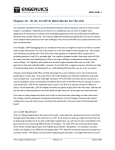
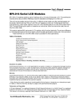
Connecting to the uM-FPU64 chip
Compiling can be done without a serial connection, but a serial connection between the computer running the IDE
and the uM-FPU64 chip is required for debugging and programming. For recent computers, the easiest way to add a
serial connection is using a USB to Serial adapter. Older computers with serial ports, or USB to RS-232 adapters
require a level converter (e.g. MAX232). The uM-FPU64 chip requires a non-inverted serial interface operating at
the same voltage as the FPU (i.e. if the FPU is operating at 3.3V, the serial interface must be a 3.3V interface). The
IDE communicates with the uM-FPU64 chip at 57,600 baud, using 8 data bits, no parity, one stop bit, and no flow
control.
Examples of suitable USB to Serial adapters include:
Sparkfun
FTDI Basic Breakout - 3.3V http://www.sparkfun.com/
Parallax
Parallax PropPlug
http://www.parallax.com/
Connection Diagram
PC running
uM-FPU64 IDE
USB
USB
USB to Serial Adapter
USB
TXD
RXD
GND
3.3V
3.3V
uM-FPU64
57,600 baud
1
MCLR
2
AN0/VREF+
3
AN1/VREF4
D5/AN2
5
D6/AN3
6
D7/AN4
7
D8/AN5
8
VSS
9
SEL
10
BUSY
11
RTC OSC1
12
RTC OSC2
13
VDD
14
SERIN
0.1 uF
Micromega Corporation
28
AVDD
27
AVSS
26
SEROUT
25
D4
24
D3
23
D2
22
D1
21
D0
20
VCAP
19
VSS
18
SOUT/SDA
17
SIN/SCL
16
SCLK
15
SS
0.1 uF
Microcontroller
Board
4.7 - 10 uF
7
uM-FPU64 IDE User Manual r411
Overview of uM-FPU64 IDE User Interface
Overview of uM-FPU64 IDE User Interface
The main window of the IDE has a menu bar, and a set of tabs attached to five different windows. Clicking a tab will
display the associated window.
Source Window
The Source Window is the leftmost tab, and the filename of the source file is displayed on the tab. If the source
file has not been previously saved, the name of the tab will be untitled. If the source file has been modified since the
last save, an asterisk is displayed after the filename. The source file is stored as a text file with a default extension of
fpu.
File Name Compile Button Target Menu Program Button
Connection Status
Source Code
Status Message
The Source Window is used to edit the source code and compile the source code. Pressing the Compile button
Micromega Corporation
8
uM-FPU64 IDE User Manual r411
Overview of uM-FPU64 IDE User Interface
will compile the code for the target selected by the Target Menu. If an error occurs during compile, then an error
message will be displayed as the Status Message. All error messages are displayed in red.
Output Window
The Output Window is automatically displayed if the compile is successful. The status message will show that the
compile was successful. All normal status messages are displayed in blue.
Output Tab
Connection Status
Button Bar
Compiler Output Window
Status Message
If the code was generated for a target microcontroller, the Select All and Copy buttons can be used to copy the
code from the window so it can be pasted into the microcontroller program. Alternatively, the code can be copy-andpasted a section at a time by doing a text selection and using the Copy button. The Remove Source button can be
used to remove the source code lines that are included as comments. The Update Target File… button is used to
update a target file with the generated code.
Micromega Corporation
9
uM-FPU64 IDE User Manual r411
Overview of uM-FPU64 IDE User Interface
Debug Window
The Debug Window is used for debugging. It displays the instruction trace, reset and breakpoint information, and
the contents of the FPU registers, string buffer and status value.
Register Display
Trace Display
Debug Display
Button Bar
Connection Status
String Buffer
Selected Name
Formatted Value
Status Byte
Status Message
The Trace Display shows messages and instruction traces. The Reset message includes a time stamp, is displayed
whenever a hardware or software reset occurs. Instruction tracing will only occur if tracing is enabled. This can be
enabled at Reset by setting the Trace on Reset option in the Functions> Set Parameters... dialog, or at any
time by by sending the TRACEON instruction.
The Debug Display provides support for source level debugging with hardware breakpoints.
The Register Display shows the value of all registers. Register values that have changed since the last update are
shown in red. The String Buffer displays the FPU string buffer and string selection, and the Status Byte shows
the FPU status byte and status bit indicators. The Register Display, String Buffer, and Status Byte are only
updated automatically at breakpoints. They can be updated manually using the Read Registers button.
Micromega Corporation
10
uM-FPU64 IDE User Manual r411
Overview of uM-FPU64 IDE User Interface
Functions Window
The Functions Window shows the function code for all new functions and stored functions. It also can be used
to program the functions into Flash memory on the FPU.
Function List
Name New Size Stored Size Compare
Connection Status
Status Message
New Function Code
Button Bar
Stored Function Code
The Function List provides information about each function defined by the compiler and stored on the FPU. The
New Function Code displays the FPU instructions for compiled functions, and the Stored Function Code
displays the FPU instructions for functions stored on the FPU. The Read Functions button is used to read the
functions currently stored on the FPU, and the Program Functions button is used to program new functions to the
uM-FPU64 chip.
Serial Trace Window
The Serial Trace Window shows a trace of the serial data exchanged between the IDE and the uM-FPU64 chip.
It’s provided mainly for diagnostic purposes.
Micromega Corporation
11
uM-FPU64 IDE User Manual r411
Tutorial 1: Compiling FPU Code
Tutorial 1: Compiling FPU Code
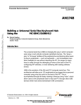
This tutorial takes you through the process of compiling uM-FPU64 code for a few simple examples. Various IDE
features are introduced as we go through the tutorial. For a more complete description of specific features, see the
the Reference Guide sections later in this document.
This tutorial uses Arduino with a SPI interface as the target. If you’re working with a different microcontroller or
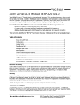
compiler, the procedures are the same, but the output code for the selected target will be different. The figure below
shows the process of developing FPU code using the IDE.
Compiling uM-FPU64 code
uM-FPU64 IDE
Microcontroller Development Tool
tutorial1.fpu
tutorial1.bs2
distance
areaIn
VAR
VAR
Word
Word
' Microcontroller variable definitions
Radius
Diameter
Circumference
Area
equ
equ
equ
equ
F10
F11
F12
F13
' FPU register definitions
Radius = distance / 1000
Diameter = Radius * 2
Circumference = PI * Diameter
Area = PI * Radius * Radius
#include <SPI.h>
#include <Fpu64.h>
#include <FpuSerial64.h>
//-------------------- uM-FPU register definitions ---------------------------#define
#define
#define
#define
' Calculations
DiameterIn
Circumference
Area
Pi
10
11
12
13
//
//
//
//
diameter in inches
circumference
area
constant pi
void setup()
{
Serial.begin(9600);
Serial.println("Sample");
SPI.begin();
Fpu.begin();
Compile
if (Fpu.sync() == SYNC_CHAR)
FpuSerial.printVersionln();
else
{
Serial.println("FPU not detected");
while(1) ; // stop if FPU not detected
}
Output window
//-------------------- uM-FPU Register Definitions ----------------------------#define Radius 10
// uM-FPU register
#define Diameter
11
// uM-FPU register
#define Circumference
12
// uM-FPU register
#define Area
13
// uM-FPU register
}
//-------------------- Variable Definitions -----------------------------------int distance;
// signed word variable
int areaIn;
// signed word variable
void loop()
{
byte diameterCm;
Copy
&
Paste
//-------------------- Generated Code -----------------------------------------// distance
VAR Word
' Microcontroller variable definitions
// areaIn
VAR Word
//
// Radius
equ F10
' FPU register definitions
// Diameter
equ F11
// Circumference equ F12
// Area
equ F13
//
// Radius = distance / 1000
' Calculations
Fpu.write(SELECTA, Radius, LOADWORD);
Fpu.writeWord(distance);
Fpu.write(FSET0, LOADWORD);
Fpu.writeWord(1000);
Fpu.write(FDIV0);
// Diameter = Radius * 2
Fpu.write(SELECTA, Diameter, FSET, Radius, FMULI, 2);
// Circumference = PI * Diameter
Fpu.write(SELECTA, Circumference, LOADPI, FSET0, FMUL, Diameter);
// Area = PI * Radius * Radius
Fpu.write(SELECTA, Area, LOADPI, FSET0, FMUL, Radius);
Fpu.write(FMUL, Radius);
//
// Load constant for later use.
Fpu.write(SELECTA, Pi, LOADPI, FSET0);
// Get diameter in centimeters. The value would typically come from a sensor
// reading, but in this example an assumed value of 25 is used.
diameterCm = 25;
Serial.print("\r\nDiameter (cm):
");
Serial.println(diameterCm, DEC);
// Convert inches to centimeters
Fpu.write(SELECTA, DiameterIn, FSETI, diameterCm);
Fpu.write(FCNV, 5);
Serial.print("Diameter (in.):
");
FpuSerial.printFloatln(0);
// circumference = diameter * pi
Fpu.write(SELECTA, Circumference, FSET, DiameterIn);
Fpu.write(FMUL, Pi);
Serial.print("Circumference (in.): ");
FpuSerial.printFloatln(0);
// area = (diameter / 2)^2 * pi
Fpu.write(SELECTA, Area, FSET, DiameterIn);
Steps
• Create FPU source code file
• Compile the FPU code
• Copy generated code to microcontroller program
• Compile microcontroller program
• Program the microcontroller
Program
Microcontroller
uM-FPU64 Chip
Micromega Corporation
12
uM-FPU64 IDE User Manual r411
Tutorial 1: Compiling FPU Code
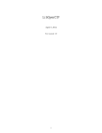
Starting the uM-FPU64 IDE
Start the uM-FPU64 IDE program. The program will open to an empty Source Window with the filename set to
untitled. Since we are using Arduino for this tutorial, use the Target Menu to select Arduino–SPI.
The Connection Status is shown at the lower left of the window. A connection is not required to use the
compiler, it’s only required for debugging and programming.
Entering a Simple Equation
The uM-FPU64 IDE has predefined names for the registers in the FPU.
F0, F1, F2, … F127 specifies registers 0 through 255, and that the register contains a floating point value
L0, L1, L2, … L127 specifies registers 0 through 255, and that the register contains a long integer
U0, U1, U2, … U127 specifies registers 0 through 255, and that the register contains an unsigned long integer
Using these pre-defined names, you can enter a simple equation directly. To add the floating point values in register
1 and register 2, and store the result in register 1, you can enter the following equation:
F1 = F1 + F2
The Source Window should look as follows:
Notice that the status line at the bottom of the window now reads Input modified since last compile. This lets you
know that you must compile to generate up-to-date output code. Click the Compile button. If the compile is
successful, the Output Window will be displayed, and the status message will be Compiled successfully for
Arduino-SPI.
If an error is detected, an error message will be displayed in red. If you get an error message, check that your input
matches the Source Window above, then click the Compile button again.
The Output Window should look as follows:
The expression F1 = F1 + F2 has been translated into Arduino code. The code selects FPU register 1 as register
A, then adds the value of register 2 to register A. You’ve successfully compiled your first compile. (If you want to
see the code generated for a different target, go back to the Source Window and select a different target from the
Target Menu.)
Micromega Corporation
13
uM-FPU64 IDE User Manual r411
Tutorial 1: Compiling FPU Code
Defining Names
Math expressions can be easier to read when meaningful names are used. The IDE allows you to define names for
FPU registers, microcontroller variables and constants.
Registers are defined using the EQU operator and one of the predefined register names. Microcontroller variables are
defined using the VAR operator. For example, the following statements define TOTAL as a floating point value in
register 1, and COUNT as a byte variable on the microcontroller.
TOTAL
COUNT
EQU
VAR
F1
BYTE
The following statement would generate code to read the value of COUNT from the microcontroller, convert it to
floating point and add it to the TOTAL register.
TOTAL = TOTAL + COUNT
Sample Project
Suppose we have a distance measuring device that returns a number of pulses proportional to distance. It measures
distance from 0 to 30 inches and returns 1000 pulses per inch. We intend to use this device to measure the radius of a
circle, then calculate the diameter, circumference and area using the FPU. The results are displayed in units of inches
to three decimal places.
Calculating Radius
The number of pulses returned by the distance measuring device ranges from 0 to 30000 (30 inches x 1000 pulses
per inch), so we will need to use a word variable to store the value on the microcontroller. Since results will be
displayed in inches, we’ll divide the distance value by 1000 once it’s loaded to the FPU chip.
Create a new source file using the File> New... menu item, and enter the following code:
distance
Radius
VAR
EQU
word
F10
Radius = distance / 1000
The Source window should look as follows:
Save the source file using the File> Save menu item. Save the file as tutorial1 (with .fp4 extension added
automatically).
Micromega Corporation
14
uM-FPU64 IDE User Manual r411
Tutorial 1: Compiling FPU Code
Click the Compile button.
The Output Window should look as follows:
The generated code does the following:
SELECTA, Radius
select the Radius register as register A
LOADWORD, distance, FSET0
load the 16-bit distance variable to the FPU, convert it to floating point, and store in Radius register
LOADWORD, 1000, FDIV0
load the floating point constant 1000, and divide the Radius register by that value
Copying Code to the Microcontroller Program
In this example we are using Arduino as the target, so open the Arduino software and open the following file:
File> Examples> Fpu64> template. Save a new copy of the template file.
Copy the uM-FPU Register Definitions and Variable Definitions from the Output Window and paste them at
the start of the template program before the setup() method.
Copy the Generated Code from the Output Window and paste it in the template program inside the loop()
method.
Since we don’t actually have the sensor described, we’ll enter a test value at the start of the program. Add the
following line at the start of the loop() method.
distance = 2575;
To print the result, add the following lines immediately after the code you copied.
Serial.print("Radius: ");
FpuSerial.PrintFloat(0);
The FpuSerial.PrintFloat method displays the value of register A as a floating point number.
Micromega Corporation
15
uM-FPU64 IDE User Manual r411
Tutorial 1: Compiling FPU Code
The main section of your Arduino program should look as follows:
#include <SPI.h>
#include <Fpu64.h>
#include <FpuSerial64.h>
//-------------------- uM-FPU Register Definitions ----------------------------#define Radius 10
// uM-FPU register
//-------------------- Variable Definitions -----------------------------------int distance;
// signed word variable
//-------------------- setup -----------------------------------------------void setup()
{
Serial.begin(9600);
Serial.println("Sample");
SPI.begin();
Fpu.begin();
// Check for synchronization and display FPU version
// (note: this is optional code)
if (Fpu.sync() == SYNC_CHAR)
FpuSerial.printVersionln();
else
{
Serial.print("uM-FPU not detected");
while(1) ; // stop if FPU not detected
}
}
//-------------------- loop ------------------------------------------------void loop()
{
distance = 2575;
//-------------------- Generated Code -----------------------------------------// distance
var
word
// Radius
equ
F10
//
// Radius = distance / 1000
Fpu.write(SELECTA, Radius, LOADWORD);
Fpu.writeWord(distance);
Fpu.write(FSET0, LOADWORD);
Fpu.writeWord(1000);
Fpu.write(FDIV0);
//
Serial.print("\r\nRadius: ");
FpuSerial.printFloat(0);
Serial.println("\r\nDone.");
while(1) ;
}
Micromega Corporation
16
uM-FPU64 IDE User Manual r411
Tutorial 1: Compiling FPU Code
Running the Program
Run the Arduino program. The following output should be displayed in the terminal window.
Calculating Diameter, Circumference and Area
Now that we have the initial program, let’s add the calculations for diameter, circumference and area. Add the
following register definitions in the start of the tutorial1.fpu:
Diameter
Circumference
Area
equ
equ
equ
F2
F3
F4
The area of a circle is twice the radius, so we add the following line to calculate diameter:
Diameter = Radius * 2
The circumference of a circle is equal to the value pi (π) times the diameter. The IDE has a pre-defined name for π,
called PI, so you can simple enter the following line to calculate circumference:
Circumference = PI * Diameter
The area of a circle is equal to pi (π) times radius squared. The POWER function could use to calculate radius to the
power of 2, but for squared values it’s easier and more efficient to simply multiply the value by itself. Enter the
following line to calculate the area:
Area = PI * Radius * Radius
Finally, we’ll read the Area value back to the microcontroller as a 16-bit integer and print the result. To do this we
first add the following definition for the microcontroller variable:
areaIn
VAR
Word
Next, we add the following line to convert the Area value to long integer and send the lower 16-bits back to
microcontroller.
areaIn = Area
Micromega Corporation
17
uM-FPU64 IDE User Manual r411
Tutorial 1: Compiling FPU Code
The Source Window should look as follows:
Click the Compile button.
Copy Revised Code to the Microcontroller Program
Copy the uM-FPU Register Definitions and Variable Definitions from the Output Window and paste them at the
start of the template program before the setup() method (replacing the previous definitions).
Copy the Generated Code from the Output Window and paste it in the template program inside the loop()
method (replacing the previous code).
Add a Serial.print and FpuSerial.printFloat statement after each of the following values are
calculated on the FPU: Radius , Diameter, Circumference and Area. FpuSerial.printFloat(63)
is used to display the floating point values in a field six characters wide with digits to the right of the decimal point.
For example:
Serial.print("Radius:
FpuSerial.PrintFloat(63);
");
Add Serial.print statements for the Arduino variable areaIn.
Serial.print("\r\nareaIn:
Serial.print(areaIn);
")
The main section of your Arduino program should look as follows:
#include <SPI.h>
#include <Fpu64.h>
#include <FpuSerial64.h>
//-------------------- uM-FPU Register Definitions ----------------------------#define Radius 10
// uM-FPU register
#define Diameter
11
// uM-FPU register
#define Circumference
12
// uM-FPU register
#define Area
13
// uM-FPU register
//-------------------- Variable Definitions ------------------------------------
Micromega Corporation
18
uM-FPU64 IDE User Manual r411
Tutorial 1: Compiling FPU Code
int distance;
int areaIn;
// signed word variable
// signed word variable
//-------------------- setup -----------------------------------------------void setup()
{
Serial.begin(9600);
Serial.println("Sample");
SPI.begin();
Fpu.begin();
// Check for synchronization and display FPU version
// (note: this is optional code)
if (Fpu.sync() == SYNC_CHAR)
FpuSerial.printVersionln();
else
{
Serial.print("uM-FPU not detected");
while(1) ; // stop if FPU not detected
}
}
//-------------------- loop ------------------------------------------------void loop()
{
distance = 2575;
//-------------------- Generated Code -----------------------------------------// distance
var Word
// areaIn
var Word
//
// Radius
equ F10
// Diameter
equ F11
// Circumference equ F12
// Area
equ F13
//
// Radius = distance / 1000
Fpu.write(SELECTA, Radius, LOADWORD);
Fpu.writeWord(distance);
Fpu.write(FSET0, LOADWORD);
Fpu.writeWord(1000);
Fpu.write(FDIV0);
Serial.print("\r\nRadius:
");
FpuSerial.printFloat(63);
// Diameter = Radius * 2
Fpu.write(SELECTA, Diameter, FSET, Radius, FMULI, 2);
Serial.print("\r\nDiameter:
");
FpuSerial.printFloat(63);
// Circumference = PI * Diameter
Fpu.write(SELECTA, Circumference, LOADPI, FSET0, FMUL, Diameter);
Serial.print("\r\nCircumference: ");
FpuSerial.printFloat(63);
Micromega Corporation
19
uM-FPU64 IDE User Manual r411
Tutorial 1: Compiling FPU Code
// Area = PI * Radius * Radius
Fpu.write(SELECTA, Area, LOADPI, FSET0, FMUL, Radius);
Fpu.write(FMUL, Radius);
Serial.print("\r\nArea:
");
FpuSerial.printFloat(63);
//
// areaIn = Area
Fpu.write(SELECTA, 0, FSET, Area, F_FIX);
Fpu.wait();
Fpu.write(LREADWORD);
areaIn = Fpu.readWord();
Serial.print("\r\nareaIn:
");
Serial.print(areaIn);
//
Serial.println("\r\nDone.");
while(1) ;
}
Running the Revised Program
Run the Arduino program. The following output should be displayed in the terminal window:
Area is displayed as 20.831, but areaIn is displayed as 20. This is because when a floating point number is
converted to a long integer it is truncated, not rounded. If you prefer the value to be rounded, then use the ROUND
function before converting the number. In the FPU source file, replace:
areaIn = Area
with:
areaIn = round(area)
Compile the FPU code, copy and paste the new code to the Arduino program. Run the program again. The following
output should now be displayed in the terminal window:
Saving the Source File
Use the File > Save command to save the file.
This completes the tutorial on compiling code for the uM-FPU64 chip. With the information gained from this
tutorial, and more detailed information from the reference section, you should now be able to use the IDE to create
your own programs.
Micromega Corporation
20
uM-FPU64 IDE User Manual r411
Tutorial 2: Debugging FPU Code
Tutorial 2: Debugging FPU Code
This tutorial takes you through some examples of debugging FPU code using the uM-FPU64 IDE. We will use the
Arduino program created in the previous tutorial for debugging.
Making the Connection
For debugging, the uM-FPU64 IDE must have a serial connection to the uM-FPU64 chip. Refer to the section at the
start of this document called Connecting to the uM-FPU64 chip.
Tracing Instructions
The Debug Window of the IDE can display a trace of all instructions as they are executed. By default, tracing is
disabled. It can be enabled at Reset by setting the Trace on Reset (Foreground) option in the Functions> Set
Parameters... dialog, or it can be turned on or off at any time by sending the TRACEON or TRACEOFF instruction.
For this tutorial we will use the Trace on Reset (Foreground) option. Select the Functions> Set
Parameters... menu item, and enable the Trace on Reset (Foreground) option as shown below.
Select the Debug Window, and click the Clear button above the Debug Trace to clear the trace area. Now run
the tutorial1 program that you developed in the previous tutorial. An instruction trace will be displayed in the
Debug Trace area. After the program stops running, click the Read Registers button to update the Register
Display, String Buffer, and Status. Scroll up to the beginning of the Debug Trace.
Micromega Corporation
21
uM-FPU64 IDE User Manual r411
Tutorial 2: Debugging FPU Code
The Debug Window should look as follows:
The reset message is displayed at the top of the screen. Every time the FPU resets, a reset message is displayed with
a time stamp. The instruction trace shows the hexadecimal bytes of the instruction on the left, followed by the
disassembled instruction. If a source file has been compiled with symbol definitions, these symbols are used when
displaying the instructions. For instructions that read data from the FPU, the trace will also display the data being
sent.
Compare the instructions in the Debug Trace to the tutorial1 program. Tracing is very useful for checking the
actual sequence of instruction executed by the FPU. Many programming errors can often be found simply by
examining the trace.
Breakpoints
A breakpoint stops execution of FPU instructions. A BREAK message is displayed in the Debug Trace and the
Register Display, String Buffer, and Status are automatically updated. This enables you to examine the state
of the FPU at that point, and then continue execution, or to single step through the code one instruction at a time.
To experiment with breakpoints, add the following statement to the tutorial1 program at the start of the loop()
method.
Fpu.write(F_BREAK);
Run the tutorial1 program again. A breakpoint occurs immediately after printing the version string. By examining
Micromega Corporation
22
uM-FPU64 IDE User Manual r411
Tutorial 2: Debugging FPU Code
the Debug Window you can see the following:
• the debug trace shows the Reset message and a trace for all previously executed instructions
• the debug trace shows the BREAK message in red
• the version string is displayed in the string buffer
• the AX beside register 0 shows that it’s currently selected as register A and register X
• register 0 is displayed in red to indicate it has a new value
• the value in register 0 is the version code
• all other registers are NaN (Not-a-Number)
Single Stepping
By single stepping through the FPU code you can see exactly what’s happening. The following example steps
through a few instructions.
Click the Step button (or type the Enter button) to single step. The Debug Window will change as follows:
• the debug trace shows the SELECTA,Radius instruction and the BREAK message
• the A beside register 10 shows that it’s now selected as register A
• register 0 is displayed in black since it hasn’t changed since the last breakpoint
• To experiment with breakpoints and single stepping, add the following line to your program at a spot that
you want a breakpoint to occur at.
Click the Step button (or type the Enter button) to single step. The Debug Window will change as follows:
• the debug trace shows the LOADWORD,2575 instruction and the BREAK message
• the A beside register 10 shows that it’s now selected as register A
• register 0 is displayed in red since it has a new value
• the value in register 0 is 2575.0
Click the Step button (or type the Enter button) to single step. The Debug Window will change as follows:
• the debug trace shows the FSET0 instruction and the BREAK message
• register 0 is displayed in black since it hasn’t changed since the last breakpoint
• register 10 is displayed in red since it has a new value
• the value in register 10 is 2575.0
To continue normal execution, click the Go button.
You can experiment further by moving the BREAK instruction to another point in your program, or by adding
multiple breakpoints. More advanced single step capabilities are available using the Auto Step button. See the
section entitled Reference Guide: Debugging uM-FPU64 Code for more information.
This completes the tutorial on debugging uM-FPU64 code. With the information gained from this tutorial, and more
detailed information from the reference section, you should now be able to use the IDE to debug your own
programs.
Micromega Corporation
23
uM-FPU64 IDE User Manual r411
Tutorial 3: Programming FPU Flash Memory
Tutorial 3: Programming FPU Flash Memory
User-defined functions and parameter bytes can be programmed in Flash memory on the uM-FPU64 chip. This
tutorial takes you through an example of creating some user-defined functions.
Making the Connection
For programming Flash memory, the uM-FPU64 IDE must have a serial connection to the uM-FPU64 chip. Refer to
the section at the start of this document called Connecting to the uM-FPU64 chip.
Defining functions
In the previous tutorials we developed and tested code to calculate the diameter, circumference, and area of a circle.
For this demonstration, we’ll define each of these calculations as a separate function.
The #function directive is used to define a function. It specifies the number of the function (0 to 63) and an
optional name.
#FUNCTION 1 GetDiameter
All code that appears after a #function directive will be stored in that function, until the next #function
directive, an #end directive, or the end of the source file. There’s an implicit RET instruction at the end of all
functions.
Functions can call other functions. To ensure that the function being called is already defined, function prototypes
can be included at the start of the program. Function prototypes are defined using the FUNC operator, which assigns
a symbol name to a function number. We’ll use function prototypes in this tutorial example. The following function
prototype defines GetDiameter as function number 1.
GetDiameter
func
1
You can assign the function number explicitly, or use the % character to assign the next unused function number.
GetDiameter
GetCircumference
GetArea
func
func
func
1
%
%
If a function prototype has been defined, the #function directive just uses pre-defined name.
#FUNCTION GetDiameter
Calling Functions
Functions are called by entering the function name in the source code.
e.g.
GetDiameter
Micromega Corporation
24
uM-FPU64 IDE User Manual r411
Tutorial 3: Programming FPU Flash Memory
Modifying the Code for Functions
Open the source file called tutorial1.fpu that you saved in the first tutorial. Add a function prototype for the three
functions called GetDiameter, GetCircumference, and GetArea. Add a #function directive before the
diameter, circumference and area calculations, and add an #end directive after the area calculation. Move the radius
calculation to after the function definitions, and add a call to the three functions. After each function call use the
directive #print_float 63 to generate code to print the floating point value in register A. The source code will
now look as follows:
distance
areaIn
VAR
VAR
Word
Word
Radius
Diameter
Circumference
Area
equ
equ
equ
equ
F10
F11
F12
F13
GetDiameter
GetCircumference
GetArea
func
func
func
' Microcontroller variable definitions
' FPU register definitions
1
%
%
' Function prototypes
#function GetDiameter
Diameter = Radius * 2
#end
' Function 1
#function GetCircumference
Circumference = PI * Diameter
#end
' Function 2
#function GetArea
Area = PI * Radius * Radius
#end
' Function 3
// main program
Radius = distance / 1000
' Calculations
GetDiameter
GetCircumference
GetArea
areaIn = ROUND(area)
Save the file as tutorial3.fp4.
Micromega Corporation
25
uM-FPU64 IDE User Manual r411
Tutorial 3: Programming FPU Flash Memory
Compile and Review the Functions
Click the Compile button. In the Output Window, the function code is displayed as comments that show the uMFPU assembler code that was generated. This is the code that will be programmed to the FPU.
// #function GetDiameter
// Diameter = Radius * 2
// SELECTA, 11
// FSET, 10
// FMULI, 2
// #end
' Function 1
The Functions Window should look as follows:
The Function List shows that three functions have been defined. The New Function Code displays the FPU
instructions for the selected function. The Stored Function Code displays the FPU instructions for the function
stored on the FPU. If no function has previously been programmed, the Stored Function Code will be empty.
You can see the code for a different function by selecting it in the Function List.
Storing the Functions
Make sure that the Overwrite Stored Functions preference is set to Always (as shown in the figure above).
Click the Program Functions button to program the functions into Flash memory on the FPU. A status dialog will
Micromega Corporation
26
uM-FPU64 IDE User Manual r411
Tutorial 3: Programming FPU Flash Memory
be displayed as the functions are being programmed. If an error occurs, check the connection. You may need to
power the uM-FPU64 chip off and then back on to ensure that it has been reset properly before trying again.
Copy Revised Code to the Microcontroller Program
Copy the uM-FPU Register Definitions and Variable Definitions from the Output Window and paste them at the
start of the template program before the setup() method (replacing the previous definitions).
Copy the Generated Code from the Output Window and paste it in the template program inside the loop()
method (replacing the previous code).
Add a Serial.print and FpuSerial.printFloat(63) statement after each of the following values are
calculated on the FPU: Radius , Diameter, Circumference and Area. FPU functions restore the register A
selection when they return, so a fpu_write(SELECTA, register) function call must be to select the
register before printing. For example:
Fpu.write(SELECTA, radius);
Serial.print("Radius:
FpuSerial.PrintFloat(63);
");
Add Serial.print statements for the Arduino variable areaIn.
Serial.print("\r\nareaIn:
Serial.print(areaIn);
")
Running the Program
Copy the generated code from the Output Window to the Arduino program, replacing the diameter, circumference
and area calculations with function calls. Remember to also copy the uM-FPU Function definitions.
The Arduino program should now look as follows:
#include <SPI.h>
#include <Fpu64.h>
#include <FpuSerial64.h>
//-------------------- uM-FPU Register Definitions ----------------------------#define Radius 10
// uM-FPU register
#define Diameter
11
// uM-FPU register
#define Circumference
12
// uM-FPU register
#define Area
13
// uM-FPU register
//-------------------- uM-FPU Function Definitions ----------------------------#define GetDiameter 1
// uM-FPU user function
#define GetCircumference
2
// uM-FPU user function
#define GetArea 3
// uM-FPU user function
//-------------------- Variable Definitions -----------------------------------int distance;
// signed word variable
int areaIn;
// signed word variable
//-------------------- setup -----------------------------------------------void setup()
{
Serial.begin(9600);
Serial.println("Sample");
Micromega Corporation
27
uM-FPU64 IDE User Manual r411
Tutorial 3: Programming FPU Flash Memory
SPI.begin();
Fpu.begin();
// Check for synchronization and display FPU version
// (note: this is optional code)
if (Fpu.sync() == SYNC_CHAR)
FpuSerial.printVersionln();
else
{
Serial.print("uM-FPU not detected");
while(1) ; // stop if FPU not detected
}
}
//-------------------- loop ------------------------------------------------void loop()
{
distance = 2575;
//-------------------- Generated Code -----------------------------------------// // main program
//
// Radius = distance / 1000
' Calculations
Fpu.write(SELECTA, Radius, LOADWORD);
Fpu.writeWord(distance);
Fpu.write(FSET0, LOADWORD);
Fpu.writeWord(1000);
Fpu.write(FDIV0);
Fpu.write(SELECTA, Radius);
Serial.print("\r\nRadius:
FpuSerial.printFloat(63);
//
// GetDiameter
Fpu.write(FCALL, GetDiameter);
Fpu.write(SELECTA, Diameter);
");
Serial.print("\r\nDiameter:
");
FpuSerial.printFloat(63);
//
// GetCircumference
Fpu.write(FCALL, GetCircumference);
Fpu.write(SELECTA, Circumference);
Serial.print("\r\nCircumference: ");
FpuSerial.printFloat(63);
//
// GetArea
Fpu.write(FCALL, GetArea);
Fpu.write(SELECTA, Area);
Serial.print("\r\nArea:
");
FpuSerial.printFloat(63);
//
// areaIn = ROUND(area)
Fpu.write(SELECTA, 0, FSET, Area, ROUND, F_FIX);
Micromega Corporation
28
uM-FPU64 IDE User Manual r411
Tutorial 3: Programming FPU Flash Memory
Fpu.wait();
Fpu.write(LREADWORD);
areaIn = Fpu.readWord();
Serial.print("\r\nareaIn:
Serial.print(areaIn);
//
");
Serial.println("\r\nDone.");
while(1) ;
}
Save the IDE source file as tutorial3.fpu and save the Arduino program tutorial3, then run the program.
The following output should be displayed in the terminal window:
Note: If the FPU functions have not been programmed to Flash memory, the output will look like the following:
Since calling an undefined functions has no effect, register A remains unchanged after the Radius
calculation, and the same value prints out for each FpuSerial.printFormat call. The AreaIn value is
displayed as -1 because the value of Area is NaN, so AreaIn is returned as -1.
Micromega Corporation
29
uM-FPU64 IDE User Manual r411
Tutorial 3: Programming FPU Flash Memory
This completes the tutorial on storing user-defined functions. With the information gained from this tutorial, and
more detailed information in the reference section, you should be able to use the IDE to define your own functions
and program them to Flash on the uM-FPU64 chip.
Micromega Corporation
30
uM-FPU64 IDE User Manual r411
Reference Guide: Menus and Dialogs
Reference Guide: Menus and Dialogs
File Menu
New…
Creates a new source file and sets the name to untitled. If a previous source file is open and has been
changed since the last time it was saved, you will first be prompted to save the previous source file.
Open…
Opens an existing source file, using the file open dialog. If a previous source file is open and has been
changed since the last time it was saved, you will first be prompted to save the previous source file.
Open Recent
Provides a sub-menu that lists up to ten source files that were recently saved. Selecting a source file from
the sub-menu will open the file. If a previous source file is open and has been changed since the last time it
was saved, you will first be prompted to save the previous source file.
Save
Saves the source file. If the source file has not been previously saved, a file save dialog will be displayed.
Save As…
Displays a file save dialog and allows a new filename to be specified.
Exit
Causes the IDE to quit. If a source file is open, and has been changed since the last time it was saved, you
will first be prompted to save the source file.
Micromega Corporation
31
uM-FPU64 IDE User Manual r411
Reference Guide: Menus and Dialogs
Edit Menu
Undo
Cancels the last edit in the Source Window.
Redo
Restores the edit cancelled by the last Undo.
Cut
Removes the selected text from the Source Window.
Copy
Copies the selected text from the Source Window to the clipboard.
Paste
Pastes the text in the clipboard to the current selection point in the Source Window.
Clear
Deletes the selected text from the Source Window.
Select All
Selects all of the text in the current text field.
Comment
Uncomment
Comment adds a semi-colon as the first character of every currently selected line in the Source
Window. This provides a way to quickly comment out a block of code. Uncomment removes the semicolon from the start of all selected lines. If all of the lines currently selected have a semi-colon as the first
character, the menu item is Uncomment, otherwise it is to Comment.
Find…
Brings up the Find Dialog.
Micromega Corporation
32
uM-FPU64 IDE User Manual r411
Reference Guide: Menus and Dialogs
The Find dialog is a moveable dialog and can be placed alongside the Source Window and left open
when multiple find and replace operations are done. The Find What field specified the string to search for,
and the Replace With field specifies the string to replace it with. If the From top search condition is
selected, the search starts from the top of the window. The search condition will automatically change to
From cursor on the first successful match. If the From cursor search conditions is selected, the search
starts from the current cursor position. When the Match case option is selected, the search is case
sensitive. The following special characters can be used in the Find or Replace strings: \t for a tab
character, \r for end of line, and \\ for backslash.
The Find Next button searches the Source Window for the next match. The Replace button replaces
the matched string. The matching text is highlighted on the first button press and replaced by the Replace
With string on the next button press. The Replace All button replaces all occurrences of the Find What
string with the Replace With string. The Close button closes the Find dialog.
Find Next
Finds the next match based on the current search conditions in the Find dialog.
Replace
Brings up the Find Dialog.
Micromega Corporation
33
uM-FPU64 IDE User Manual r411
Reference Guide: Menus and Dialogs
Debug Menu
Select Port…
Displays the Port Setup dialog which is used to select the serial communications port.
Reset
This menu item sends the reset command to the uM-FPU64.
Stop
Go
Step
Step Over
Step Out
These menu items have the same function as the Go, Stop, Step, Step Over and Step Out buttons in
the Debug Window.
Auto Step
Continues execution in auto step mode. See the section entitled Reference Guide: Auto Step and
Conditional Breakpoints for more details.
Auto Step Conditions
Micromega Corporation
34
uM-FPU64 IDE User Manual r411
Reference Guide: Menus and Dialogs
Brings up the Auto Step Conditions dialog. See the section entitled
Reference Guide: Auto Step and Conditional Breakpoints for more details.
Turn Trace On
Turn Trace Off
These menu items have the same function as the Trace button in the Debug Window.
Read Registers
This menu item has the same function as the Read Registers button in the Debug Window.
Read Version
Displays the version of the FPU in the Debug Trace.
Read Checksum
Displays the checksum of the FPU in the Debug Trace.
Micromega Corporation
35
uM-FPU64 IDE User Manual r411
Reference Guide: Menus and Dialogs
Functions Menu
Select Port…
Display the Port Setup dialog which is used to select the serial communications port.
Program Flash Memory
Has the same function as the Program Functions button. It programs the user-defined functions to the
FPU chip.
Clear Flash Memory
Clear all of the user-defined functions from Flash memory on the uM-FPU64 chip. A dialog will be
displayed requesting confirmation before the functions are cleared from memory.
Read Functions
Has the same function as the Read Functions button. It reads the flash memory and updates the function
list in the Function Window.
Set Parameters…
Brings up the Set Parameters… dialog to set the FPU parameter bytes. See the section entitled Reference
Guide: Setting uM-FPU64 Parameters for more details.
Micromega Corporation
36
uM-FPU64 IDE User Manual r411
Reference Guide: Menus and Dialogs
Tools Menu
Number Converter
Brings the Number Converter window to the front. The number converter provides a quick way to
convert numbers between various 32-bit and 64-bit formats. Floating point, decimal and hexadecimal
numbers are supported. The Auto, Float, Decimal, and Hexadecimal buttons above the Input field
determine how the input is interpreted. If Auto is selected, the input type is determined automatically
based on the characters entered in the Input field. The input type is displayed to the right of the Input field.
The input type can be manually set using the Float, Decimal and Hexadecimal buttons. Invalid
characters for the selected type are displayed in red, and will be ignored by the converter. The Output
fields display the input value in all three formats. The hexadecimal value can be displayed in 8-bit, 16-bit,
32-bit, or 64-bit format, with a choice of prefix characters. The format can be selected to match the format
used by microcontroller programs.
One of the handiest ways of using the number converter is with copy and paste. You can copy a number
from program code or a trace listing, and paste into the Input field. The Input field accepts floating point
numbers, decimal numbers, and hexadecimal numbers in 8-bit, 16-bit, 32-bit, and 64-bit formats. You can
copy from the Output fields to program code.
Micromega Corporation
37
uM-FPU64 IDE User Manual r411
Reference Guide: Menus and Dialogs
Interactive Compiler
Brings the Interactive Compiler window to the front. The interactive compiler window takes source
code, compiles the code and sends it to the uM-FPU64 instruction buffer. This can be used for a variety of
testing applications. User-defined functions can be called, devices can be accessed using FPU instructions,
etc. The instruction buffer is cleared before the compiled code is sent. If the FPU is running, the code will
be executed immediately. If the FPU is currently at a breakpoint, the instructions will be executed when the
next Go or Step command is issued.
Only equations, procedures and assembly code are supported by the interactive compiler, but all of the
symbol definitions from the last source code compile can be used in the interactive compiler window.
For example:
Call procedure main:
main
Initialize the LCD on pin 0 and write a test string:
devio(LCD, ENABLE, 0, ROWS_4+COLS_20)
devio(LCD, WRITE_STR, “test”)
Initialize variables and call functions and XOPs:
Micromega Corporation
38
uM-FPU64 IDE User Manual r411
Reference Guide: Menus and Dialogs
The Import button loads previously saved interactive compiler code from a text file.
The Save button saves the interactive compiler code to a text file.
The Check button compiles the code and checks for errors.
The Compile and Send button compiles the code and sends it to the FPU instruction buffer.
The Read Registers button reads the FPU registers and displays them in the Debug Window.
The Reset button sends a rest command to the FPU.
Compiler code can be entered interactively, with context sensitive menus available to assist. A control-click
inside the interactive compiler window displays a context-sensitive pop-up menu of all registers, constants,
procedures, functions, and operators that are currently defined. Selecting an item from the pop-up will
insert that item into the interactive compiler window. This is a useful way to test user-defined functions.
Once the functions are programmed into Flash, the interactive compiler window can be used to call the
functions for testing. Equations and procedure calls use the same syntax as the source code compiler.
Micromega Corporation
39
uM-FPU64 IDE User Manual r411
Reference Guide: Menus and Dialogs
Firmware Update…
This menu item is used to update the uM-FPU64 firmware. Firmware files are provided as part of the uMFPU64 IDE installation and are installed in the Firmware folder. When the Firmware Update… menu
item is selected (or button is pressed), a dialog is displayed to select the firmware file to install.
Note: There are two types of uM-FPU64 firmware. The 28-pin chips require firmware files that
have 64K28 as part of the filename. The 44-pin chips require firmware files that have 64K44
as part of the filename.
Once the firmware file has been selected a dialog is displayed that shows a description of the firmware file
and displays the status and progress of the firmware upgrade. The upgrade process only takes a few
seconds. When the upgrade is complete a Firmware upgrade completed status message will be
displayed.
Note: It’s important that a stable 3.3V operating voltage is provided to the uM-FPU64 chip during
the firmware upgrade, and that the upgrade process is not interrupted.
Micromega Corporation
40
uM-FPU64 IDE User Manual r411
Reference Guide: Menus and Dialogs
Window Menu
Show Main Window
Brings the main IDE window to the front.
Serial Setup Options…
Displays a tabbed dialog that is used to set the display type for each of the serial windows.
Micromega Corporation
41
uM-FPU64 IDE User Manual r411
Reference Guide: Menus and Dialogs
Show Serial Window
Brings the serial window selected from a hierarchical menu to the front.
Micromega Corporation
42
uM-FPU64 IDE User Manual r411
Reference Guide: Menus and Dialogs
Show Flash Memory…
Displays a memory map showing the usage of the Flash memory reserved for user-defined functions on the
uM-FPU64 chip. A status line at the top shows the percent of memory used and the number of bytes
available.
Show RAM Window
Brings the RAM Display window to the front. This window is used to view the contents of RAM.
Micromega Corporation
43
uM-FPU64 IDE User Manual r411
Reference Guide: Menus and Dialogs
Memory Allocation shows the allocation of RAM to the various memory areas.
Foreground
Memory allocated to the foreground process.
Background
Memory allocated to the background process.
Other
Memory allocated to FIFO1, FIFO2, FIFO3, FIFO4, and any loadable devices.
DMA
DMA memory. Used by the ADC instructions. Can be accessed with indirect pointers.
The Load Pointers button set the description, type and value fields for any foreground pointer currently
loaded in the Register display of the Debug window. If the pointer is an array pointer, each element of the
array is added as a description.
The Read Memory button reads the current contents of RAM and updates the displays. If the memory
allocation has changed, the formatted display is cleared, and the last format file used is reloaded. All RAM
values that have changed since the last read are highlighted in red, and all non-zero values are shown with a
Micromega Corporation
44
uM-FPU64 IDE User Manual r411
Reference Guide: Menus and Dialogs
light yellow background.
The Clear Format button clears the formatted display. If the RAM format file default.txt exists in the ~/
My Documents/Micromega/RAM Files folder it will be loaded and the formatted display is updated.
The Load Format button loads a RAM format file and updates the formatted display.
The Save Format button saves a RAM format file.
The Hex Display shows the value of each byte in RAM as a hexadecimal value. The current selection in
the formatted display outlined with a box in the hex display. Clicking in the hex display will select the
corresponding item in the formatted display. Values that have changed since the last time RAM was read
are highlighted in red, and non-zero value are shown with a light yellow background.
The Formatted Display shows the RAM contents formatted according to the type specified. Each row in
the formatted display can have a separate description, type, and modifier. The description, type and modifer
can be entered using a RAM format file, or entered interactively using the Change RAM Format dialog that
is displayed by right-clicking on a row in the formatted display. Multiple rows can be changed by first
selecting the multiple rows, then right-clicking within the selection.
The Description field can be used to enter any text string that doesn’t include a double quote (“) character.
There are some special cases:
n
The type and modifier will be repeated n times specified (where n is a
decimal number).
*
name[i]
name[i, j]
name[i, j, k]
The type and modifier will be repeated until the end of the memory area.
Specifies an array name, with the dimensions of the array given by i, j and
k. For each element of the array, the description will be set the the name of
the element and the type and modifier will be repeated.
If you wish to use one of the special cases as a description, without it being handled as a special
case, then the description should be enclosed in double quotes (“). (e.g. ”name[2,2,2]” will
not be expanded into multiple array elements).
RAM Format Files are text files containing a description of the format to use in the formatted display.
They are stored in the ~/My Documents/Micromega/RAM Files folder. The autosave.txt file is saved
automatically to the ~/My Documents/Micromega/RAM Files folder when the RAM Display window is
Micromega Corporation
45
uM-FPU64 IDE User Manual r411
Reference Guide: Menus and Dialogs
closed, and loaded when the RAM Display window is first opened. The RAM format file default.txt is used
to specify the default format for the formatted display. If default.txt exists in the ~/My Documents/
Micromega/RAM Files folder it will be loaded when the Clear Format button is pressed. Other files can be
written and edited by the user. The RAM format files can contain the following lines:
Header
<RAM FORMAT> or <RAM FORMAT OVERLAY>
This must be the first line of the file. The <RAM FORMAT> line indicates that the file contains
a full format description. The formatted display is cleared before loading the format file. The
<RAM FORMAT OVERLAY> line indicates that the file is an overlay. The descriptions and
types defined in the file will be added the existing formatted display.
Comment
; comment
Any line that begins with a semi-colon (;) is a comment line. The autosave.txt file adds
comments showing the date and time and the memory allocation in effect when the file was
saved.
Memory Area
<FOREGROUND>
<BACKGROUND>
<DMA>
<FIFO1> to <FIFO4>
<DEVICE1> to <DEVICE6>
Specifies the memory area for the description lines that follow. An optional offset can be
added as a second argument (e.g. <FOREGROUND, 100>). This specifies a decimal offset
into the memory area for the next description line. The offset can also have multiple decimal
values that are added together (e.g. <FOREGROUND, 100+10>).
Description
description, type, modifier
The description can be any text string that doesn’t include a double quote (“) character. There
are some special cases:
n
The type and modifier will be repeated n times specified (where n is a
decimal number).
*
The type and modifier will be repeated until the end of the memory area.
name[i]
name[i, j]
name[i, j, k]
Specifies an array name, with the dimensions of the array given by i, j and
k. For each element of the array, the description will be set the the name of
the element and the type and modifier will be repeated.
If you wish to use one of the special cases as a description, without it being handled as a
special case, then the description should be enclosed in double quotes (“). (e.g.
”name[2,2,2]” will not be expanded into multiple array elements).
If the description string contains a comma, or you wish to use one of the special cases without
Micromega Corporation
46
uM-FPU64 IDE User Manual r411
Reference Guide: Menus and Dialogs
it being handled as a special case, then the description must be enclosed in double quotes (“).
(e.g. ”name[2,2,2]” will not be expanded into multiple array elements).
The type can be one of the following: INT8, UINT8, INT16, UINT16, LONG32, ULONG32,
FLOAT32, LONG64, FLOAT64.
The modifier is optional, and if not specified no modifier is used. The modifier can be one of
the following: HEX, BIN, ASC. The BIN modifier only displays the lower 16 bits if the type is
greater than 16 bits. The ASC modifier displays the ASCII value of the lower 8 bits.
Show Matrix Window
The Matrix Display window is brought to the front. This window is used to view the contents of matrix A,
matrix B, and matrix C. The matrix values are not updated automatically, they must be updated manually
using the Update button.
Micromega Corporation
47
uM-FPU64 IDE User Manual r411
Reference Guide: Menus and Dialogs
The Display as Zero option can be used to display values that are close to zero as ~0.0.
A zero comparison value from 1e-1 to 1e-15 can be selected from the pop-up menu. If the absolute value of
the matrix element is less than the zero comparison value, the value is displayed as ~0.0.
Display as Zero: off
Micromega Corporation
Display as Zero: < 1e-6
48
uM-FPU64 IDE User Manual r411
Reference Guide: Menus and Dialogs
Help Menu
uM-FPU64 IDE User Manual
uM-FPU64 IDE Compiler
uM-FPU64 Instruction Set
uM-FPU64 Datasheet
These menu items display documentation files using the default PDF viewer. The IDE will open the files on
the Micromega website using the default web browser.
Micromega Website
Opens the Micromega website using the default web browser.
Application Notes
Opens the application notes page on the Micromega website using the default web browser.
About uM-FPU64 IDE
Displays a dialog with product identification, release version and release date of the uM-FPU64 IDE
software. A link to the Micromega website is also provided
Micromega Corporation
49
uM-FPU64 IDE User Manual r411
Reference Guide: Compiler and Assembler
Reference Guide: Compiler and Assembler
The uM-FPU64 IDE provides a compiler and assembler for generating uM-FPU64 code for either a target
microcontroller, or for user-defined functions that are stored in Flash memory on the FPU. The Source Window
has a built-in editor for entering the source code. The source code will be converted to FPU instructions by the
compiler and assembler. The output format is customized to the correct syntax for the target microcontroller selected
by the user. FPU functions can be stored in Flash memory on the uM-FPU64 chip.
Symbol definitions can include constants, FPU registers, pointers, arrays, and microcontroller variables. Math
equations can use 32-bit or 64-bit integer and floating point values, and can contain defined symbols, math
operators, functions and parentheses. The compiler also supports an in-line assembler for entering FPU instructions
directly.
See the uM-FPU64 IDE Compiler document for a description of the compiler and assembler.
Source Window
The source code for the program is entered into the Source Window.
File Name Compile Button Target Menu Program Button
Connection Status
Micromega Corporation
Source Code
Status Message
50
uM-FPU64 IDE User Manual r411
Reference Guide: Compiler and Assembler
The source window provides tab processing and auto-indent to make entering code easier and to improve the layout
of source files. All tab characters are replaced by one or more spaces.
Automatic Tab Replacement
When a source file is opened by the IDE, or text is pasted into the source window, all tab characters are replaced by
spaces to approximate the old tab settings. Saved files will no longer contain tab characters.
Tab Processing
When a tab key is pressed in the source window, the following actions now occur:
Tab with No Selection
If the line immediately above the current line has a space in the same position, spaces will be inserted
into the current line until the first non-space character in the line above. This makes it easy to line up
the columns text such as definitions or comments. If the line immediately above the current line has a
non-space character in the same position, then spaces will be added until the next tab stop. The tab stop
for the first 20 characters of a line is two, and the tab stop after 20 characters is four. This makes it easy
to indent code, but saves typing later in the line when tabbing to a particular column.
Tab with Text Selection
An indent is inserted by adding two spaces to the start of all lines covered by the text selection. The
text selection remains in place.
Shift-Tab
An indent is removed by deleting up to two spaces from the start of the current line, and if text is
selected, from all lines covered by the text selection. The text selection remains in place.
Delete
If a delete character is entered immediately after a tab or auto-indent, the last tab stop will be deleted.
Auto-Indent
If a return key or shift-return key is entered at the end of a source code line, the following actions occur:
Return
If a directive or control statements is detected on the current line, the next line will be indented by two
additional spaces, otherwise the next line will have the same indent as the current line. The recognized
directives or control statements are as follows:
#function
#asm
do
while
for
if...then
else
elseif
select
case
Shift-Return
A shift-return key causes the same action as the return key, but also appends the matching end statement. The
Micromega Corporation
51
uM-FPU64 IDE User Manual r411
Reference Guide: Compiler and Assembler
cursor is positioned on the next line. The matching end statement are as follows:
#function
#end
do
loop
if...then
endif
#asm
#endasm
while
loop
select
case
endselect
for
next
Output Window
The compiled code is displayed in the Output Window.
Output Tab
Connection Status
Micromega Corporation
Button Bar
Compiler Output Window
Status Message
52
uM-FPU64 IDE User Manual r411
Reference Guide: Compiler and Assembler
Updating Target Files with Linked Code
Target code generated by the compiler can by manually copied to target source files using copy-and-paste. An
automated update method is available using the Update Target File... button in the Output Window. To use the
automated update method, special comments are inserted into the target source file to define the begin and end points
for code insertion. These special comments, or links, are generated by the compiler. Links are automatically
generated for register definitions, function definitions, and variable definitions. An example of a register definition
link is shown below:
// [--- uM-FPU64 ---] Begin Register_Definitions
#define Radius
10
// uM-FPU register
#define Diameter
11
// uM-FPU register
#define Circumference
12
// uM-FPU register
#define Area
13
// uM-FPU register
// [--- uM-FPU64 ---] End Register_Definitions
Other user-defined links are generated by using the #target_code link_id directive in the FPU file. For
example, using the following directive in the FPU file:
#target_code calculations
Will generate the following code in the Output Window.
// [--- uM-FPU64 ---] Begin calculations
//
Radius = distance / 1000 ' Calculations
Fpu.write(SELECTA, Radius, LOADWORD);
Fpu.writeWord(distance);
Fpu.write(FSET0, LOADWORD);
Fpu.writeWord(1000);
Fpu.write(FDIV0);
// [--- uM-FPU64 ---] End calculations
To initially insert links into the target source file, copy-and-paste the links from the Output Window to the target
source file.
When the Update Target File... button is pressed, a dialog is displayed so the user can select a target file. Any link
in the target file with a matching link in the Output Window will be updated with the code from the Output
Window. A timestamp comment is added to the start of the linked code stored in the target file. Linked code is
inserted into the target file using the indentation of the begin link in the target file. This allows the inserted code to
be properly aligned with other target code.
Micromega Corporation
53
uM-FPU64 IDE User Manual r411
Reference Guide: Compiler and Assembler
Reference Guide: Debugger
Utilizing the built-in debug monitor on the uM-FPU64 chip, the IDE provides a high-level interface for debugging
programs that use the uM-FPU64 floating point coprocessor. It supports the ability to trace uM-FPU instructions, set
breakpoints, single-step through execution of uM-FPU instructions, and display the value of uM-FPU registers. The
IDE includes a disassembler so that instruction traces are displayed in easy-to-read assembler format.
Making the Connection
For debugging, the uM-FPU64 IDE must have a serial connection to the uM-FPU64 chip. Refer to the section at the
start of this document called Connecting to the uM-FPU64 chip.
Source Level Debugging
Source level debugging is only available for user-defined functions. The source file is displayed below the trace
display. A movable divider is located between the trace display and debug display. Breakpoints can be set on any
executable line shown in the debug display (both source level and assembler). All executable lines have an expand/
collapse icon. Source lines can be expanded to display the assembler code generated by the source line. When the
debugger is active, a cursor shows the next instruction to be executed. If a source line is expanded, the debugger will
step by assembler instruction. If the source line is collapsed, the debugger will step by source line.
Debug Window
Trace Display
Debug Display
Connection Status
Register Display
Button Bar
Selected
Name
Formatted Value
String Buffer
Status Message
Moveable Divider
Status Byte
Source-level Debug Display
Micromega Corporation
54
uM-FPU64 IDE User Manual r411
Reference Guide: Compiler and Assembler
Source Code (expanded)
Assembler
Source Code (collapsed)
Breakpoint
Cursor
Breakpoint
Expand/Collapse
Icon
Left column:
Right column:
Breakpoint and cursor display.
Source code and assembler code display.
White background:
Gray background:
Yellow background:
Source code (non-executable).
Source code (executable).
Assembler code (executable).
Double-click on left column (executable line):
Sets or clears breakpoint.
If no previous breakpoint, sets the next breakpoint.
If no more breakpoints, displays a placeholder.
If breakpoint or placeholder present, they are cleared.
Right-click on left column:
Double-click on right column (executable line):
Expands or collapses the individual line.
Breakpoints are cleared on lines that are collapsed.
Cursor is moved to expanded or collapsed line.
Right-click on right column:
Micromega Corporation
55
uM-FPU64 IDE User Manual r411
Reference Guide: Compiler and Assembler
Debug Buttons
Stop Go
Step
Step Over
Step
Out
Auto
Step
Stop
• Stop execution and enter debugger.
Go
• Start or continue execution.
Step
• Step to next executable line.
• If source code is unexpanded, the step is to next executable source line.
• If source line is expanded, the step is to next assembler instruction.
Step Over
• Step to next executable line in the same function (steps over function calls).
• If source code is unexpanded, the step is to next executable source line.
• If source line is expanded, the step is to next assembler instruction.
Step Out
• Steps out of current function.
Auto Step
• Functionality is unchanged from previous version.
The Trace Display displays messages and instruction traces. The Reset message includes a time stamp, is is
displayed whenever a hardware or software reset occurs. Instruction tracing will only occur if tracing is enabled.
This can be enabled at Reset by setting the Trace on Reset option in the Functions> Set Parameters... dialog,
or at any time by sending the TRACEON instruction.
The Register Display shows the value of all registers. Register values that have changed since the last update are
shown in red. The String Buffer displays the FPU string buffer and string selection, and the Status Byte shows
the FPU status byte and status bit indicators. The Register Display, String Buffer, and Status Byte are only
updated automatically at breakpoints. They can be updated manually using the Read Registers button.
The Go, Stop, Step and Trace buttons at the top left control the breakpoint and trace features, and the connection
status is displayed at the lower left of the window.
Micromega Corporation
56
uM-FPU64 IDE User Manual r411
Reference Guide: Compiler and Assembler
Trace Display
The scrolling window on the left of the debug window displays the debug trace output. When a Reset occurs a
message is displayed showing the date and time of the Reset.
---------------------------------------RESET: 2011-09-27 13:19:31
----------------------------------------
Tracing is turned off at Reset, unless the Trace on Reset parameter has been set. Tracing can be controlled by the
program using the TRACEON and TRACEOFF instructions, or manually with the Trace button. If tracing is enabled,
all FPU instructions are displayed as they are executed. The opcode and data bytes are displayed on the left, and the
FPU instructions are displayed on the right in assembler format.
TRACE: ON
0104
5E
29
2401
2401
1F3F
F232302E3833
3100
SELECTA, 4
LOADPI
FSET0
FMUL, 1
FMUL, 1
FTOA, 63
READSTR: "20.831"
The Trace button toggles the trace mode on and off.
Clicking the Clear button above the Debug Trace window will clear the contents of the Debug Trace window.
Breakpoints
Breakpoints can be inserted into a program using the BREAK instruction, or initiated manually with the Stop button.
Breakpoints occur after the next FPU instruction finishes executing. When a breakpoint occurs, the last FPU
instruction executed before the breakpoint is displayed, followed by the break message, and the register display is
updated. Register values are displayed in red if the value has changed since the last time the display was updated, or
black if the value is unchanged.
5E
LOADPI
BREAK
The Go, Stop, and Step buttons are enabled or disabled depending on the current state of execution. The Go
button is used to continue execution, and is enabled at Reset or after a breakpoint occurs. The Stop button is used to
stop execution after the next FPU instruction is executed. If the uM-FPU is idle when the Stop button is pressed,
the breakpoint will not occur until the next uM-FPU instruction is executed. If the FPU is already at a breakpoint,
then the Stop button will be disabled. The Step button is used to single step through instructions, with a new
breakpoint occurring after each instruction.
The Register Panel
The register panel displays the value of each register and indicates the register currently selected as register A and
register X. Register A and register X are indicated by an A and X marker in the left margin of the register panel. The
temporary registers are displayed at the bottom on the register panel.
For each register, the register number, optional register name, and formatted value is displayed. If you right-click on
the formatted value, a pop-up menu is displayed with the register value displayed in hexadecimal, floating point,
long integer, and unsigned long integer format. If you select a different format, the display will be updated to show
that format. The format of multiple registers can be changed by selecting a group of registers prior to the right-click
Micromega Corporation
57
uM-FPU64 IDE User Manual r411
Reference Guide: Compiler and Assembler
for the format pop-up menu.
Register names are automatically set from the register definitions in the source file. Registers can often have several
different names assigned. If you right-click on the register name, a pop-up menu is displayed showing all of the
names for that register. If you select a different name, the display will be updated to show that name.
If you right-click on the register number, a pop-up menu is displayed that always you to scroll the display to the
register A value, register X value, the 32-bit registers (0-127), or the 64-bit registers (128-255).
The current register values are automatically updated after every breakpoint. The Read Registers button can also
be used to manually force an update of the register values. Register values are displayed in red if the value has
changed since the last time the display was updated, or black if the value is unchanged.
Micromega Corporation
58
uM-FPU64 IDE User Manual r411
Reference Guide: Compiler and Assembler
Error messages
<data error>
The IDE communicates with the uM-FPU64 chip using a serial connection. If the IDE detects an error in the
data received from the FPU, the data error message is displayed in the Debug Trace. This can sometimes
occur immediately before a Reset, if the reset interrupts a trace operation in progress. This situation can be
ignored. If it occurs at other times it indicates a problem with the serial communications. The trace in the Serial
I/O window can be reviewed and may help determine the source of the problem.
<trace suppressed>
In certain circumstances, the FPU is capable of sending data faster than the PC can handle it. If this occurs, the
trace suppressed message is displayed, and the IDE attempts to recover by suppressing data, resynchronizing,
and continuing. This situation should not normally occur, but can occur if excessive amounts of trace data are
being produced such as tracing a user-defined function that is looping. To avoid this situation, the TRACEOFF
and TRACEON instructions can be used to selectively disable tracing.
<trace limit xx>
The IDE will retain up to 100,000 characters in the Debug Trace. This is normally more than sufficient for
tracing and debugging. The Debug Trace buffer can be cleared with the Clear button. If the buffer is
exceeded, the first portion will be deleted, and the trace limit message displayed in its place. The trace limit
messages are numbered sequentially. This message does not necessarily indicate an error, unless it occurs in
conjunction with one of the messages described above.
FPU Error: Address error
An address error occurred inside an XOP instruction. The likely cause is an invalid parameter being specified in
an XOP instruction.
FPU Error: Buffer overflow
The 256 byte FPU instruction buffer has been exceeded. This can be avoided by waiting for a ready status at
least every 256 bytes, if more than 256 byes are sent to the FPU between read operations. If debug trace is
enabled, instructions take longer to execute, particularly if the serial buffer fills, which can sometimes lead to an
FPU buffer overflow that doesn’t occur an normal execution speed.
FPU Error: Call level exceeded
The 16 levels of call nesting available on the uM-FPU64 has been exceeded.
FPU Error: Device not loaded
A DEVIO,device,LOAD_DEVICE,… instruction failed because the loadable device was not
programmed into Flash memory.
FPU Error: Function not defined
A user function has been called that has is not currently stored in FPU Flash memory.
FPU Error: Incomplete Instruction
An instruction that requires multiple bytes has not received the required number of bytes within the timeout
period of one second. This is generally caused by a programming error in the target code.
FPU Error: Invalid parenthesis
There are 8 levels of parentheses available using the LEFT and RIGHT instructions. Either too many LEFT
instructions have been sent, or there is a mismatch with the number of LEFT and RIGHT instructions.
FPU Error: Memory Allocation failed
A memory allocation failed because the number of bytes requested were not available in the dynamic
allocation area.
FPU Error: XOP not defined
An extended opcode (XOP) was called that is not currently stored in FPU Flash memory.
Micromega Corporation
59
uM-FPU64 IDE User Manual r411
Reference Guide: Auto Step and Conditional Breakpoints
Reference Guide: Auto Step and Conditional Breakpoints
The Auto Step feature provides a means to automatically single step through FPU instructions. This feature, in
conjunction with Auto Step Conditions, can be used to implement conditional breakpoints. Conditional breakpoints
stop instruction execution when one of the specified conditions occur. Breakpoints can be set for a variety of
conditions including: when a particular instruction is executed, when a user-defined functions is called, when a
specified number of instructions have been executed, when a register value changes or matches a particular
expression, or when a string comparison matches a particular condition. Multiple conditions can be specified, and a
breakpoint will occur when any of the conditions is met.
Conditional breakpoints are only active when the Auto Step operation is used. They are not active when the Go or
Step operation is used. Instruction execution is much slower using Auto Step since an internal breakpoint occurs
for each instruction, and the debug trace and register data are checked for Auto Step Conditions.
Auto Step is activated by clicking the Auto Step button, or selecting the Debug> Auto Step menu item.
Auto Step Conditions are set by right-clicking the Auto Step button, or selecting the Debug> Auto Step
Conditions menu item. The Auto Step Conditions can also be set to appear each time the Auto Step button is
pressed.
Auto Step Conditions Dialog
Micromega Corporation
60
uM-FPU64 IDE User Manual r411
Reference Guide: Auto Step and Conditional Breakpoints
Break on Instruction
This condition causes a breakpoint when a particular instruction is executed. The instruction is specified using
assembler format as shown below.
The opcode can be selected from a pop-up menu,
or the opcode can be typed in the field. An auto-complete feature is provided to assist in typing the opcode.
Break on FCALL
This condition causes a breakpoint when a user-defined function is called, or when it returns.
The function is selected from a pop-up menu. The menu has all of the function numbers. If functions have been
defined in the current source file, and compiled, the function name is also displayed in the menu. The special item
<any function> can also be selected to cause a breakpoint on any function call.
Micromega Corporation
61
uM-FPU64 IDE User Manual r411
Reference Guide: Auto Step and Conditional Breakpoints
Break on Count
This condition causes a breakpoint after a specified number of instructions has executed.
Break on Register Change
This condition causes a breakpoint when the value changes in one of the specified registers.
Multiple registers can be specified separated by commas. A register can be specified as:
• a single register value (e.g. 1)
• a range of register values (e.g. 3-10 which selects registers 3 through 10)
• an array of register values (e.g. 20:2 which selects two registers starting at registers 20)
If register names have been defined in the current source file, and compiled, the names can also be used.
Break on Expression
This condition causes a breakpoint whenever the expression is true.
The left side of the expression must be a register. A register number can be typed in, or if registers have been defined
in the current source file, and compiled, a pop-up menu can be used.
Micromega Corporation
62
uM-FPU64 IDE User Manual r411
Reference Guide: Auto Step and Conditional Breakpoints
The operator used by the expression is chosen from the middle pop-up menu
The operators are as follows:
=
equal
<>
not equal
>
greater than
>=
greater than or equal
<
less than
<=
less than or equal
=~
approximately equal
The approximately equal operator is used for floating point values. The condition is true if the register value is
greater than (value - 0.000001) and less than (value + 0.000001).
The left side of the expression can be any value. The value can be typed in or the pop-up menu can be used for
predefined values.
Micromega Corporation
63
uM-FPU64 IDE User Manual r411
Reference Guide: Auto Step and Conditional Breakpoints
Break on String
This condition causes a breakpoint if the string comparison is true.
The string comparison can either be the entire string buffer, or the current string selection. The comparison operator
is selected from the left pop-up menu, and the string to compare is entered in the field on the right.
The comparisons for length require a decimal number to be entered in the field on the right. The comparisons for
selection, length require two decimal numbers separated by a comma to be entered in the field on the right.
Micromega Corporation
64
uM-FPU64 IDE User Manual r411
Reference Guide: Programming Flash Memory
Reference Guide: Programming Flash Memory
The Function window provides support for storing user-defined functions on the uM-FPU64 chip. Stored functions
can reduce memory usage on the microcontroller, simplify the interface and often increase the speed of operation.
The uM-FPU64 reserves 2048 bytes of flash memory for user-defined functions and parameters (plus 256 bytes for
the header information). Functions are stored as a string of FPU instructions, and up to 64 functions can be defined.
Functions are specified in the source file by using the #FUNCTION directive. See the section entitled Reference
Guide: Generating uM-FPU64 Code for more details.
Function Window
Function List
Name New Size Stored Size Compare
Connection Status
Status Message
New Function Code
Button Bar
Stored Function Code
The Function List provides information about each function defined by the compiler and stored on the FPU. The
Name column in the Function List displays the name of all functions defined in the source file. The New column
shows the size in bytes of the functions defined in the source file, and the Stored column displays the size in bytes
of functions currently stored on the FPU. If nothing is displayed in the Stored column, the Read Stored
Functions button can be pressed to read the stored functions from the FPU. The = column displays Yes if the new
and stored functions are the same, or No if they are different. The total bytes used in the New column and Stored
Micromega Corporation
65
uM-FPU64 IDE User Manual r411
Reference Guide: Programming Flash Memory
column is displayed at the top of the function list.
The New Function Code displays the FPU instructions for compiled functions, and the Stored Function Code
displays the FPU instructions for functions stored on the FPU. The function to be displayed is selected by selecting
one of the functions in the Function List.
The Read Stored Functions button is used to read the functions currently stored on the FPU and update the
Function List.
The Program Functions button is used to program new functions to the uM-FPU64 chip. If a newly defined
function is different then the currently stored functions, the action taken is determined by the Overwrite Stored
Functions option.
If the Always option is selected, a new function will always overwrite any previously stored function.
If the Confirm with User option is selected, you are asked to confirm whether a new function should replace the
previously stored function.
If the Never option is selected, new functions are not allowed to replace previously stored functions.
Micromega Corporation
66
uM-FPU64 IDE User Manual r411
Reference Guide: Setting uM-FPU64 Parameters
Reference Guide: Setting uM-FPU64 Parameters
The Set Parameters… menu item is used to set the uM-FPU64 mode parameter bytes.
Set Parameters Dialog
Break on Reset
If this option is selected, a breakpoint will occur on the first instruction following a Reset.
Trace on Reset (Foreground)
If this option is selected, debug tracing is turned on at Reset for foreground tasks.
Trace Inside Functions (Foreground)
If this option is selected, debug tracing will be enabled inside functions called by foreground tasks.
Trace on Reset (Background)
If this option is selected, debug tracing is turned on at Reset for background events.
Trace Inside Functions (Background)
If this option is selected, debug tracing will be enabled inside functions called by background events.
Disable Busy/Ready status on SOUT
Micromega Corporation
67
uM-FPU64 IDE User Manual r411
Reference Guide: Setting uM-FPU64 Parameters
If this option is selected, the Busy/Ready status will not be output on the SOUT pin, and the /BUSY pin must be
monitored for the Busy/Ready status.
Use PIC Format (IEEE 754 is default)
If this option is selected, the PIC format will be used for reading and writing floating point values. The uM-FPU64
chip uses floating point values that conform to the IEEE 754 32-bit floating point standard. This is also the default
format for reading and writing floating point values in FPU instructions. An alternate PIC format is often used by
PICmicro compilers. If this option is selected, floating point values are automatically translated between the PIC
format and the IEEE 754 format whenever values are read from the FPU or written to the FPU, and the
microcontroller program can use the PIC format. The IEEEMODE and PICMODE instructions can also be used to
dynamically change the format. For additional information regarding the IEEEMODE and PICMODE instructions,
see the uM-FPU64 Instruction Set.
Note: The IDE code generator currently only generates code for the default IEEE 754 format. If
the PIC format is used you will need to fix the data values in the code generated for FWRITE,
FWRITEA, FWRITEX and FWRITE0 instructions.
Idle Mode Power Saving Enable
If this option is selected, the uM-FPU64 chip will go into a low power mode when idle.
Sleep Mode Power Saving Enabled
If this option is selected, the uM-FPU64 chip will go to sleep when idle and the chip is not selected. This mode is
only active if the interface mode is SPI with the CS pin used as a chip select.
Interface Mode
This option selects which digital I/O pin will be used for the external input, and specifies the active edge.
Interface Mode
By default, the SEL pin on the uM-FPU64 chip is read at Reset to determine if the SPI or I2C interface is to be used.
The interface mode parameter can be used to force selection of SPI or I2C at Reset (ignoring the SEL pin).
I2C Address
By default, the I2C address used by the uM-FPU64 chip is C8 (hexadecimal) or 1100100x (binary). If the default
address conflicts with another I2C device, or if multiple uM-FPU64 chips are used on the same I2C bus, the address
can be changed to any other valid I2C address. The address is entered as an 8-bit hexadecimal number (with the
lower bit ignored). A value of 00 will select the default C8 address.
Auto-Start Mode
A user-defined function can be called and Debug Mode can be disabled when the FPU is Reset. If the Disable
Debug option is selected, Debug Mode will be disabled at Reset. This is useful if the SERIN and SEROUT pins are
being used for other purposes (e.g. GPS input, LCD output) and prevents the {RESET} message from being sent to
the SEROUT pin at Reset. If the Call Function option is selected, the specified function will be called at Reset.
These options are only checked if the CS pin is Low at Reset. If both the CS pin and SERIN pin are High at Reset,
the auto-start function is not called, and Debug Mode will always be entered. This provides a way to override the
auto-start mode once it is set. To use auto-start with an I2C interface, the interface mode bits must be set to I2C (as
described above). It’s recommended that the interface be set to SPI or I2C using the interface bits whenever autostart mode is used, so that the CS pin can be used to enable or disable the auto-start mode.
3.3V / 5V (Open Drain) Pin Settings
Micromega Corporation
68
uM-FPU64 IDE User Manual r411
Reference Guide: Setting uM-FPU64 Parameters
For pins that are 5V tolerant, the output can be defined as open drain to allow a 5V output using a pull-up resistor.
Restore Default Settings
This button restores the parameters to the following default settings:
Break on Reset
Trace on Reset (Foreground)
Trace Inside Functions (Foreground)
Trace on Reset (Background)
Trace Inside Functions (Background)
Disable Busy/Ready status on SOUT
Use PIC format (IEEE 754 is default)
Idle Mode Power Saving Enabled
Sleep Mode Power Saving Enabled
External Input
Interface Mode
I2C address
Auto-Start Mode> Disable Debug
Auto-Start Mode> Call Function
3.3V / 5V (Open Drain) Pin Settings
Micromega Corporation
not enabled
not enabled
not enabled
not enabled
not enabled
not enabled
not enabled
enabled
not enabled
D8, rising edge
SEL pin selects interface (default)
C8
not enabled
not enabled
all set to 3.3V
69
uM-FPU64 IDE User Manual r411
Reference Guide: SERIN and SEROUT Support
Reference Guide: SERIN and SEROUT Support
The uM-FPU64 IDE uses the SERIN and SEROUT pins for communication with the debug monitor. It also supports
the ability to debug a project that uses the SERIN and SEROUT pins, and to receive serial data from multiple serial
devices. If the debug monitor is enabled, the FPU communicates with the IDE to get data for the SERIN instruction,
and sends data to the IDE from the SEROUT instruction. The SEROUT instruction supports three extra devices that
can be used for sending data to the IDE. If the debug monitor is not enabled, output from the additional SEROUT
devices is suppressed.
Note:
To use the IDE support for the SERIN and SEROUT instructions, the debug monitor on the FPU
must be active. All SEROUT,SET_BAUD instructions that disable the debug monitor must be
commented out while debugging.
SERIN Window Setup Options
The SERIN window is configured using the Window> Show Serial Window> Setup Options menu item. It
can be configured for Text Input or Terminal Emulation mode. In Terminal Emulation mode, serial input and output
are both handled by the SEROUT window.
SERIN Window - Text Input, Character Mode
When the SERIN,ENABLE_CHAR instruction is executed the IDE enters character mode. When a
SERIN,READ_CHAR instruction is executed, the IDE waits for the user to send the next character. The characters
to send can be entered manually in the SERIN window or imported from a text file. In Text Input mode, the text is
not actually sent to the FPU until you select a character or group of characters, and press one of the send buttons.
The Send button sends the single character at the start of a selection. The Send and Repeat button sends each of the
selected characters, in sequence, one at a time, as each SERIN,READ_CHAR instruction is executed. The user is not
prompted for additional input until the selection has been completely sent. The repeat action can be stopped by
making another selection.
Micromega Corporation
70
uM-FPU64 IDE User Manual r411
Reference Guide: SERIN and SEROUT Support
SERIN Window - Text Input, NMEA Mode
When the SERIN,ENABLE_NMEA instruction is executed the IDE enters NMEA mode. When a
SERIN,READ_NMEA instruction is executed, the IDE waits for the user to send the next NMEA sentence. The
sentences to send could be entered manually in the SERIN window, but they are normally imported from a text file.
The sentences are not actually sent to the FPU until you select a sentence or group of sentences, and press one of the
send buttons. The Send button sends the single sentence at the start of a selection. The Send and Repeat button sends
each of the selected sentences, in sequence, one at a time, as each SERIN,READ_NMEA instruction is executed. The
user is not prompted for additional input until the selection has been completely sent. The repeat action can be
stopped by making another selection. Only complete sentences are sent to the FPU. If only part of a sentence is
selected, the complete sentence will be sent.
Micromega Corporation
71
uM-FPU64 IDE User Manual r411
Reference Guide: SERIN and SEROUT Support
SEROUT Window Setup Options
The SEROUT window is configured using the Window> Show Serial Window> Setup Options menu item. It
can be configured for Text Output, Terminal Emulation, or Table and Graph mode.
SEROUT Window - Text Output Mode
In Text Output mode, data sent by the SEROUT instruction is displayed in a text window, in black, with no additional
formatting. The text output can be exported to a text file. If a vertical tab character (\v, or \0B) is received from the
FPU, the SEROUT display is cleared.
Micromega Corporation
72
uM-FPU64 IDE User Manual r411
Reference Guide: SERIN and SEROUT Support
SEROUT Window - Terminal Emulation Mode
In Terminal Emulation mode, serial input and serial output are both handled by the SEROUT window. Data sent by
the SEROUT instruction is shown in blue, with no additional formatting. Characters typed by the user are shown in
red. They are not displayed until the SERIN instruction requests data. A typeahead buffer is provided. If a vertical
tab character (\v, or \0B) is received from the FPU, the SERIN/SEROUT display is cleared.
Micromega Corporation
73
uM-FPU64 IDE User Manual r411
Reference Guide: SERIN and SEROUT Support
SEROUT Window - Table and Graph Mode
In Table and Graph mode, data sent by the SEROUT instruction is displayed in a table and graph. The data in each
column in displayed in a different color, and each column is graphed using a line of the same color. The X and Y
scales for the graph are automatically calculated to display the entire data set.
Data received from the SEROUT instruction must be comma separated values terminated with a carriage return. If
the values are non-numeric, they are displayed as column headings. If the values are numeric, a new row of data is
added to the table.
The new SEROUT(WRITE_FLOAT…), SEROUT(WRITE_LONG…), SEROUT(WRITE_COMMA), and
SEROUT(WRITE_CRLF) instructions make it easy to create comma separated values. If a vertical tab character (\v,
or \0B) is received from the FPU, the SEROUT display is cleared.
Table
Column Headings
Graph
Cursor
Export File
Save the data to a comma separated value (CSV) file.
Clear
Clears the table and graph.
The cursor displayed on the graph corresponds to the currently selected row in the table. The cursor can also be
Micromega Corporation
74
uM-FPU64 IDE User Manual r411
Reference Guide: SERIN and SEROUT Support
dragged left and right, or stepped left and right using the left and right arrow keys. The selected row in the table and
the cursor on the graph are linked, so that changing one will also change the other. This makes it easy to identify the
numeric value of any point on the graph.
By default all columns are displayed on the graph, but the graph line for a column can be turned on and off by
clicking on the column heading. When the graph line for a column is turned off, [OFF] will be displayed at the end
of the column heading, and the column is not displayed on the graph.
SEROUT Device 1, Device 2, Device 3 Setup Options
The SEROUT - Device1, SEROUT - Device 2, and SEROUT - Device 3 windows are configured using the
Window> Show Serial Window> Setup Options menu item. They can be configured for Text Output or Table
and Graph mode. The capabilities of these modes are the same as described for the SEROUT window, with the
exception of Terminal Emulator mode, which is only available for the SEROUT window.
The SEROUT Devices have no physical output, and are only supported by the IDE. They can be used for logging
background information for testing and debugging. For example run-time statistics could be logged to one of the
SEROUT Device windows. If the debugger is disabled, SEROUT instructions for devices 1, 2 and 3 are ignored by
the FPU so there is very little overhead for a program that is not being debugged.
Micromega Corporation
75
uM-FPU64 IDE User Manual r411