1
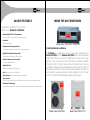
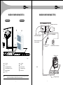
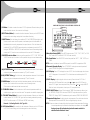
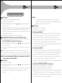
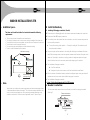
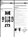
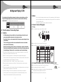
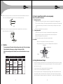
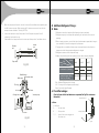
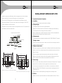
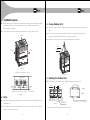
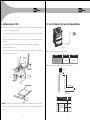
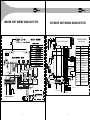
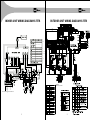
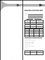
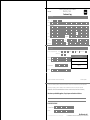
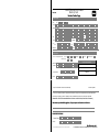
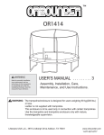
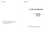
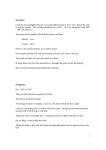
INSTALLATION OF OUTDOOR UNIT 8.75TR
?
In order to suppress noise effectively, install noise suppression and should insulation
devices, especially in the noise-sensitive spaces such as meeting rooms.
£
Important: Construction Checkpoints:
?
For connection of the flange plane, use non-flammable canvas adapter to prevent
£
Installation:
transmission of vibration. For its size, see the indoor unit outline diagram. Use M6 X 20
?
check the model and name to avoid mistaken installation.
screws (configured on site) for connection.
£
Refrigerant pipe:
?
All pipelines must be connected closely and soundly without leak of air. The pipelines must
?
The refrigerant pipes must have the specified diameter.
?
Nitrogen of a certain pressure must be filled into the refrigerant pipe before welding.
be adiabatic and free from condensation.
?
The refrigerant pipe must undergo heat insulation treatment.
?
After the refrigerant pipe is installed completely, the indoor unit cannot be powered on
Key points of duct connection
before performing the airtight test and creating a vacuum.
Canvas adapter Canvas adapter
£
Refrigerant pipe:
2
The refrigerant pipe must undergo the airtight test (with 2.94MPa (30kgf/cm G) nitrogen.)
Noise suppression room
?
Creating a vacuum:
?
Be sure to use the vacuum pump to create a vacuum of the connective pipe at both air
Air outlet
Noise
suppression room
Inspection
orifice
Air inlet
side and liquid side concurrently.
Air filter
£
Refrigerant replenishment:
?
If the pipe is longer than the reference pipe, the refrigerant replenishment quantity for each
Fig.40
outdoor unit should be calculated through the formula obtained according to the actual
length of the pipe.
1350
390
?
Record the refrigerant replenishment quantity, actual length of pipe and the height
1350
390
difference of the indoor & outdoor units onto the operation confirmation table (on the
1225
electric control box) of the outdoor unit in advance for future reference.
450
300
300
300
(Unit:mm)
Fig.41
362.5
Air outlet duct connection screw hole location diagram
250
?
Select the power supply capacity and wire size according to the design manual. The power
wire size of the air conditioner should be greater than that of ordinary motors.
?
In order to prevent misoperation of the air conditioner, do not interleave or entwine the
40
25
25
45
343
236
16 5
450
£
Electric wiring:
362.5
(Unit:mm)
Fig.42
Return air duct rivet screw hole location diagram
power cable (380v-415v 3N 50Hz) with the connection wires (low-voltage wires) of the
indoor/outdoor unit.
?
Power on the indoor unit after performing the airtight test and making vacuum.
£
Trial Run:
?
Perform the trial run only after the outdoor unit has been powered on for over 12 hours.
39
40