1
Insulation and Continuity Testing
Introduction
The PDIT 360 requires 4 x AA cells (alkaline type recommended)
that must be inserted with correct polarity. ALWAYS REMOVE THE
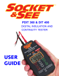
The PDIT 360 is a simple and rugged instrument for use by
electrical installers in testing the continuity of electric cables as well
as their insulation resistance. The tester is only for use on dead
circuits and although fully protected against accidental connection
to a live circuit, it always pays to to check that the circuit is dead
TEST LEADS BEFORE REPLACING THE BATTERIES. Four full
capacity alkaline AA cells are expected to have a life of 5000 tests
at 500 V. Battery life is extended because the PDIT 360 captures
the test result very quickly and will automatically switch off if not
used for two or three minutes.
before working on it. The safety check is fully explained in the
Continuity Testing
section headed “Continuity Testing”.
The tester is equipped with a very useful “hands free” auto
testing facility as described in the section headed “Hands Free
Function”. Do not touch the test lead tips when this test mode is
in use. All electrical circuits have a property called “capacitance”,
its presence being indicated by the insulation test result taking
longer than usual to appear. Capacitance may result in the test
voltage being stored for a short time when testing insulation
resistance. The PDIT 360 has a facility to automatically discharge
The purpose here is to ensure that a circuit is continuous so that
current will flow in it, and to measure its resistance. Before using
the instrument, it is important to ensure that the circuit under test
is not live. First switch off the supply at the main isolator in the
consumers unit (See Fig 1) and then remove its cover (See Fig 2).
1 Turn off the isolator at the consumer unit
this voltage, but do not disconnect the test leads until discharge is
complete, usually in no more than a few seconds.
Check the condition of the test leads and crocodile clips frequently.
Socket & See replacement lead sets are inexpensive and easy to
obtain. The continuity function is protected against accidental
connection to the mains (an unlikely event as there is a built-in
warning system. If the fuse does blow, replace it with the correct
type which is Type F 500mA fast blow ceramic 500 V. It is located
inside the battery compartment.
2 Remove the consumer unit cover
1
2
3
Live Circuit
Warning
Continuity
Test
6
LCD Display
Power
ON/OFF
(including
Intelligent
Auto Power
Off)
4
Insulation
Test
5
Insulation
Test Voltage
250V
500V
Continuity
Test Lead Null
7
Next make sure that the system really is dead by switching the
Briefly Push to
Test (Instant)
plus
Push and Hold
for 2 seconds
for Auto Test
(Hands Free)
tester on and placing the probes carefully on the input terminals of
the isolator (See Fig 3). The red WARNING VOLTAGE PRESENT
indicator at the top of the front panel will flash and a warning tone
8
will be heard. Next remove the probes and reposition them on the
output terminals of the isolator (See Fig 4). There should be no
warning light or tone, indicating that safe continuity testing can
commence.