1
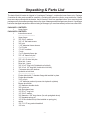
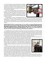
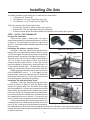
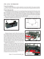
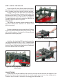
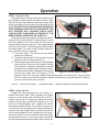
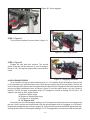
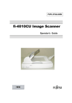
MODEL 4 TUBE B ENDER
Assembly & Operating Instructions
Revision 2
JD Squared Inc.
© Copyright 2000 by J D Squared Inc.
Unpacking & Parts List
The basic Model 4 bender is shipped in 2 packages. Package 1 contains the lower frame only. Package
2 contains all other parts needed for assembly, excluding the hydraulic cylinder, pump and hose. If these
items were also ordered with the bender, they will arrive in their own separate boxes. Upon receiving both
packages verify that neither package shows any signs of damage and that all parts are present. If a package
has been damaged and parts are either missing or damaged, you must immediately contact our sales office.
PACKAGE 1 CONTENTS:
1
Lower frame
PACKAGE 2 CONTENTS:
1
Instruction manual
-----------------------------1
Upper frame
11
3/4" S.A.E. washers
3
3/4" x 2" flat head screws
3
3/4" nuts
3
1 1/2" diameter frame sleeves
3
1" x 8" bolts
6
1" S.A.E. washers
3
1" nuts
1
1" x 8" diameter frame pin
2
7/8" x 8" frame link pins
-----------------------------1
7/8" x 6 1/4" drive link pins
1
Drive link - Lower
1
Drive link - Upper
1
3/4"-16 x 5" long bolt (Outside drive link bolt)
1
3/4"-16 x 4 1/2" long bolt (Inside drive link bolt)
2
1" diameter drive link sleeves
1
Hydraulic swivel block
-----------------------------1
Pusher block with 1" diameter flange bolt welded in place
1
Pusher block handle
1
3/16" roll pin
1
1 1/2" diameter pushrod (screws into hydraulic cylinder)
1
Bronze pivot block
2
1/2" diameter shoulder bolts
1
3/8" nylock nut
1
Anti-Springback lever
1
1/2"-20 x 1" long bolt
1
1/2" S.A.E. washer
1
3/4" diameter x 3/8" long sleeve (for anti-springback lever)
1
1/2" threaded spring pin
1
1/2"-20 fine thread nut (will be installed on spring pin)
1
spring
1
1/4" x 1 1/2" long socket head bolt
2
1/4" nuts
-1-
Assembly
1) The bender may be mounted to anything rigid enough not to twist or move during
the bending operation. To mount the bender, drill three 3/4" holes through your
mounting surface. You can use the frame holes as a guide. Place two 3/4" washers
on the top of each drilled hole. These washers will act as spacers to insure that the
bender pins, when installed, will be completely pass through the lower frame holes.
If you purchased the optional pedestal, position the washers over the slots as shown
in figure 1.
Figure 1
Upper Frame Link
2) Refer to figure 2. Using three 3/4" x 2" long flat head
bolts, three 3/4" nuts and three 3/4" washers, tightly
secure the frame to your mounting surface/pedestal.
Using three 1 1/2" diameter frame sleeves, three 1"
diameter x 8" long bolts, six 1" washers and three 1" nuts,
install the upper frame onto the lower frame. Lightly
tighten the bolts. Next install the 1" frame pin as shown
in figure 2. Using a small square placed against the 1"
pin, move the upper frame around until the frame pin is
perfectly vertical. Tighten all three 1" bolts.
Figure 2 - Upper frame installed
4) Remove the 1" frame pin. Locate the lower drive link. It will
have two 3/4" tapped holes in it and a recess milled out of its
bottom side's center. Place it on the lower frame with its inside 1"
hole over the lower frame's 1" center hole and its milled recess
facing down. Replace the 1" frame pin. Locate the hydraulic
cylinder's swivel block. Examining the swivel block you will see
the word 'TOP' stamped into it. Insert the swivel block into the
lower drive link's remaining 1" hole with the word 'TOP' facing up.
Your Model 4 should now look like figure 3.
Figure 3
3) Refer to figure 4 for this step. Remove the 1" frame pin. Locate the
upper drive link. Place it in the bender so that it aligns with the lower
drive link and engages the swivel block's upper shaft. Reinstall the 1"
frame pin. Place the two 1" diameter drive link sleeves between the two
drive links aligned with the 3/4" holes. Place a 3/4" washer onto the 3/
4"-20 x 5" long bolt. Install it into the outside 3/4" sleeve and lightly
tighten. Place a 3/4" washer onto the 3/4"-20 x 4 1/2" long bolt. Install
it into the inside 3/4" sleeve and tighten securely. Remove the whole
drive link assembly and turn upside down. Look on the bottom side of
the lower link and verify that the inside 3/4" bolt threads do NOT
protrude out of the link. If it does, it will severely scratch the frame's
machined surface. Also the bender's links will not ride properly on the
lower frame. The only way this should be able to occur would be if the
longer 5" bolt was installed where the 4 1/2" bolt should be.
-2-
Hydraulic
Swivel
Block
Lower Drive Link
Figure 4 - Drive links installed
4) Invert the drive link assembly as shown in figure 7.
Anti-Springback
Locate the parts listed below:
lever
1 Anti-Springback lever
1 1/2"-20 x 1" long bolt
1 1/2" S.A.E. washer
1 3/4" diameter x 3/8" long sleeve
1 1/2" threaded spring pin
1 1/2"-20 fine thread nut
1 1/4" x 2" long socket head bolt
2 1/4" nuts
1 Spring
Place the 1/2" washer onto the 1/2"-20 x 1" long bolt.
Figure 5 - Anti-springback lever
Next place the 3/4" diameter sleeve onto the bolt also. This
sleeve acts as a spacer. Study figures 5 and 7 carefully and
Spring Pin
then position the anti-springback lever as shown. Install the
1/4" Bolt
bolt, washer and sleeve through the anti-springback lever
and into the lower drive link. Tighten securely. Verify that the
lever rotates freely.
Install the 1/2"-20 fine thread nut onto the spring pin
about half way up. Install the spring onto the spring pin as
shown in figure 6. Screw the spring pin into the lower link
until it starts to protrude out the other side of the drive link.
Figure 6 - Spring installation
Back it off 1 to 2 turns, to make sure it doesn't protrude, and
tighten the 1/2" nut.
Install a 1/4" nut onto the 1/4" x 2" long socket head bolt.
Adjust the 1/4" nut so that when the bolt is installed in the
anti-springback lever, the 1/4" nut on the other side of the
anti-springback lever can be completely installed with only
1 thread visible. This will put the bolt's head roughly even
with the spring pin's head. Remove the 1/4" bolt. Being
careful not to turn the 1/4" nut already installed, insert the
bolt's head through the open loop of the spring. Holding the
bolt, stretch the spring and insert the bolt back into the 1/4"
hole in the anti-springback lever. Install the other 1/4" nut
Figure 7 - Lever system installed
onto the bolt from the top side of the anti-springback lever
and tighten. Remember that only one thread of the 1/4" bolt should be visible from the top side of the antispringback lever. Figures 6 and 7 show the complete assembly correctly installed. Note that the outside 3/
4" bolt protrudes out of the bottom of the lower drive link and that the inside 3/4" bolt does NOT.
Install the completed drive link assembly into the bender. The easiest way to do this is from the rear of
the bender. Insert the drive link assembly
with the open 1" holes between the 1" holes
in the frame. Insert the 1" frame pin. Now
rotate the drive link assembly
counterclockwise until it rest on the
machined upper surface of the frame. If it
does lay flat, the upper frame link will need
to be loosened and repositioned until the 1"
frame pin is perfectly vertical. Rotate
assembly until the degree scale reads 30 to
60 degrees on the right side of the lower
drive link.
Figure 8
-3-
5) Locate the parts shown in figure 9 and listed below:
1 Pusher Block
1 Pusher Block Handle
1 Bronze Pivot Block
1 Pushrod (1 1/2" diameter)
2 1/2" x 2 1/2" long shoulder bolts
1 3/16" roll pin
1 3/8" nylock nut
1 1" diameter welded flange bolt
NOTE: This bolt is shown as a seperate
item in figure 9 for easier identification.
However, It has already been welded into
the Pusher Block.
Pushrod
Pusher Block
1" Welded
Flange Bolt
Bronze Pivot Block
Pusher Block Handle
Figure 9 - Pusher assembly
Bronze Pivot
Block Upper Side
Examine the bronze pivot block. You will notice
that the 1/2" hole has been offset drilled to one
side as shown in figure 10. The distance from the
hole's edge to the pivot block's side will be less
than the other three sides. This is the pivot
block's upper side. Now examine the pusher
block. You will see a 1 1/2" slot milled completely
Figure 10
through its top surface and on its bottom you will
see a smaller recess milled into it's front edge. Note: The pusher block
shown in figure 9 is bottom side up so that the milled recess can be
clearly seen. This recessed area is where the bronze pivot block is
installed. Hold the pusher block so that the engraving on its side is
right side up and facing you. Position the bronze pivot block into the
lower recess so that its upper surface is facing up (the hole is offset
to the top). From the engraved side of the pusher block, insert one of
the two 1/2" shoulder bolt and secure tightly with the 3/8" nylock nut.
When completed it should look like figure 11. The pivot block must
also be protruding out of the bottom of the pusher block approximately
1/16" as shown in figure 12. If it's not, it's installed wrong and must be
reinstalled.
As shown in figure 13, position the pushrod into the pusher block's
upper slot. The 1/2" hole in the pushrod nearest to the end should be
lined up with the 1/2" hole in the pusher block. Insert a 1/2" shoulder
bolt into the pusher block from the side opposite the engraving. Install
the pusher block handle onto this shoulder bolt and tighten. Lay the
pusher block down on the side opposite the engraving. Slightly rotate
the pushrod so that the 1/2" hole in its middle is under the 3/16" hole
drilled into the engraved side of the pusher block. Being careful not to
mar the engraved face of the pusher block, hammer in the 3/16" roll
pin until it is flush with the pusher block's surface. Figure 11 shows this
step completed.
Figure 13
Pusher assembly complete
-4-
Figure 11 - Pusher block
Figure 12
6) Screw the hydraulic cylinder completely into the hydraulic
swivel block. If when tightened the cylinder's quick disconnect
hose fitting is not facing in the downward direction, loosen the
cylinder until it does face in the downward direction. The
cylinder will have a little play in its threads. This is normal and
will not cause any problems.
Screw the completed pusher block assembly into the
cylinder. You may need to rotate the drive links to the rear of
the bender in order for the handle to clear the main frame as
the pusher block is screwed into the cylinder. Rotate the
pusher block so that the handle is facing toward you. Rotate
the drive links until the pusher block is positioned approximately
as shown in figure 14.
Figure 14 - Pusher block engaged
Using the handle, move the 1" welded flange bolt into one
of the lower frame's teeth. When the bender is under load, the rear of the pusher blockshould rise
approximatley 1/16" above the face milled flat of the lower frame. With the bronze pivot block protruding
out of the bottom of the pusher block 1/16", this should make the pusher block ride flat when bending. This
will eliminate any side loads on the hydraulic cylinder, therefore preventing any unnecessary wear in the
cylinder.
IMPORTANT NOTE: Looking at figure 14, you will see a hole drilled through the
drive links just outboard of the cylinder pivot block. NEVER OPERATE THE
BENDER HYDRAULICALLY WITH A PIN IN THIS HOLE, AS IT WILL DAMAGE
THE CYLINDER HOUSING BEYOND REPAIR. This hole is only used when the
bender has the optional manually pulled handle installed.
7) Next attach the hose to the pump in its correct port. If you have your own pump or purchased a pump
with your bender and it wasn't the 2 HP model, follow the directions included with the pump. If you purchased
the preferred 2 HP pump as shown in figure 15, you can look at the photo as a reference. Wrap 2 to 3 layers
of teflon tape around the male threads on the hydraulic hose. Looking at the bender from the electric motor
side, screw the hose into the right side upper port. Wrap 2 to 3 layers of teflon tape around the 1/2" pipe
plug and screw it into the left side upper port. Make sure both are tightened snugly.
Attach the hose to the cylinder's quick disconnect fitting and hand tighten only. Plug the pump into the
proper electrical outlet. Note: Upon start up, if the pump acts like it's not
getting enough current, take these steps to fix the problem. First use a heavy
gauge (12 gauge or heavier), short electrical extension cord. The shorter the
better. If using 110 volts, make sure the electrical circuit breaker is rated at
least 30 amps. As a general rule, if when the bender is operating, the
electrical extension cord feels hot, it's too small. Also if the electrical relay
operates erratically when pressed, it's probably a sign of an electrical supply
problem.
Pressing the pump control buttons will extend the cylinder under
pressure or release the pressure, thereby retracting the cylinder using its
internal spring return. If neither button is pressed the cylinder will hold its
position. The 2 HP pump is relatively fast. It's easy to overshoot the desired
bend angle. To prevent this from happening, follow this procedure: Press the
cylinder extend button and hold down until the bender is 3-5 degrees before
the desired angle. Now quickly tap the button on and off until the bender
Figure 15
edges up to the proper degree. With practice you should easily be able to
advance the cylinder as little as 1/5 of a degree. Note the 5000 p.s.i. pressure gauge shown in figure 15.
This gauge is not included with the pump, but is highly recommended. A good quality gauge can be
purchased at any hydraulic supply business. Simply tee it into the pressure hose as shown in figure 15.
-5-
Installing Die Sets
The Model 4 bender comes with 4 pins. Locate the pins listed below:
1 1" Diameter x 8" Frame Pin
2 7/8" Diameter x 8" Long Frame Pins (Long Pin)
1 7/8" Diameter x 6 1/4" Long Drive Pin (Short Pin)
A Die Set consists of the 3 parts listed below:
1 Forming Die (Circular in shape, usually with a groove)
1 Pressure Die (The part that slides along the workpiece)
1 U-Block (A small square block that retains the workpiece, also usually has a groove)
STEP 1 - INSTALL THE FORMING DIE
Forming Die Installation
There are two styles of forming dies. One has a
square block welded to its backside as shown in left side
of figure 17. The other doesn't as shown in right side of
figure 17. The method of die installation depends on what
style you have.
Installing a Die without a welded block:
Figure 16 - Die styles
Using the 1" frame pin, place the forming die into the
bender with its rounded side forward as shown in figure
1" Frame Pin
7/8" Frame Pin
18. The forming die will normally only have one other hole
Forming Die
drilled through it, as shown on the right side of figure 17.
This hole is very close to the die's edge, usually within a
1/8"-1/4". If there is more than one hole, use the hole
closest to the die's edge. Model 1, 2 and 3 die sets will
work in the Model 4, however they usually will have 3 to
5 holes drilled through them. So with those dies you
would only use the hole closest to the flat side of the die.
Rotate the die until the hole in the die lines up with one
of the NUMBERED holes 1 - 4 in the frame (not the
lettered holes). Insert one of the two long 7/8" frame pins
through the frame and die. This pin will prevent the die
Figure 17 - Die installed
from rotating when the bender is operating.
Installing a Die with the welded block:
Using the 1" frame pin, place the forming die into the
bender as shown in figure 19 with the welded block
Drive Holes
closest to the frame bolts. The die shown has multiple
drive holes drilled in it. Only the one closest to the die's flat
side (it will be the one nearest to the welded block) needs
to be used. A long 7/8" frame pin has been installed in the
hole closest to the dies welded block. Installed this way
the welded block serves no function. This would be the
case if a Model 3 die set was being used in the Model 4.
If the forming die does NOT have any drive holes, only
a welded block, then install the die as shown but do not
Figure 18 - Die with welded block
use a 7/8" pin. In this case, when the bender is operating,
the welded block on the die will rotate clockwise and contact the workpiece, thus preventing the die from
rotating. Note that if the die has a welded block and drilled drive holes you can use either the welded block
or the first drive hole.
-6-
STEP 2 - INSTALL THE PRESSURE DIE
Pressure Die Installation
Pressure dies are machined to exacting standards and must be installed in the proper orientation.
Depending on whether the die set is for pipe, round or square tubing follow the appropriate directions below.
ROUND TUBING OR PIPE
The pressure die is shown in figure 19. For round tubing and pipe, the pressure die will have two circular
grooves machined on each end, a leading and a trailing groove. The trailing side groove is machined at an
angle. This angled groove provides better control of the workpiece than a straight groove, resulting in a
better bend quality. However, the pressure die MUST be installed in the bender's drive links with the angled
groove closest to the forming die. If the pressure die is installed upside down, that is with the angled groove
forward, it will try to dig into the workpiece and bend quality will suffer.
Engraved into the pressure die will be the O.D. size of the tubing or pipe and the correct hole number
that it should be installed into the drive links with.
Straight Groove
Straight Groove
Angled Groove
Angled Groove
Figure 20 - Top view drawing
Figure 19 - Tube or pipe Pressure Die
Straight Groove
Referring to figures 21 and 22. After the forming die has
been installed, rotate the drive links counter-clockwise until
they are parallel with the upper frame link. Place the tubing
or pipe to be bent through the middle of the drive links as
shown. Next place the pressure die between the drive links
with the angled groove closest to the forming die. The
angled groove should now be towards the rear of the bender
and on your right side. Insert a short 7/8" pin through the
drive links and the pressure die in the exact hole number
engraved into the pressure die.
NOTE: The angled groove supports the tube during the
bending process, thereby preventing it from excessively
flattening on the outside. Never install the pressure die
upside-down with the angled groove not at the point of bend
(closest to the forming die). It can damage the pressure die
and severely gouge your tube or pipe. Also, if the pressure
die is placed in a hole# other than the one marked on it, bend
quality will suffer. If the tube or pipe is flattening a large
amount on the outside, check to make sure the pressure die
is installed in the correct drive link hole.
Figure 22 - Pressure Die installed - back
-7-
Figure 21 - Pressure Die installed - front
Angled Groove towards
back of bender
STEP 3 - INSTALL THE U-BLOCK
Shown in figure 23 is the U-Block installed in the bender.
Normally the pressure die would have already been installed,
but for a clearer view of the u-block it has been removed.
Looking at the top of the upper frame you will see two
rows of 7/8" holes with letters or numbers beside them. The
front seven row holes (1,2,3,4,E,F,G) are in a straight line
and the back seven holes (A,B,C,D,5,6,7) are staggered.
The back side holes are the ones where the U-Block pin is
normally installed as shown in figure 23.
PROCEDURE:
The forming die, pressure die and workpiece (tube or
pipe) have already been installed in the bender in the
previous two steps.
Figure 23 - U-block installed
Position the workpiece where you want it bent. Referring
to figure 24, push the workpiece away from you firmly. This
will seat the workpiece in between the forming die and
pressure die, removing any play.
Figure 24 - Pushing workpiece
Install the u-block and long 7/8" frame pin into one of the
7/8" back side holes AS CLOSE TO THE 1" FRAME PIN AS
POSSIBLE. This is why you had to push the workpiece away
from you. Figure 26 shows the complete die set installed as
seen from the back side of the bender.
Figure 25 - Installing pin in back hole
Figure 26 - Die set installed as seen from back
side of bender
SQUARE TUBING
Square tube die sets are installed in the same way as round tube die sets with the exception of the
pressure die. Square tube pressure dies do not have an angled groove, just one long straight groove.
Therefore, all you need to do is install it in the correct hole# as marked on it.
-8-
Operation
STEP 1 - Figure 27 & 28
Using your hands, rotate the drive links clockwise until
the workpiece is firmly seated in the die set with no play.
With the cylinder fully retracted, extend the cylinder while
guiding the pusher block into the first ratchet tooth on the
frame. DO NOT PLACE YOUR HANDS ANYWHERE ON
THE PUSHER BLOCK EXCEPT ON THE HANDLE. THIS
WILL PREVENT ANY POSSIBLE PINCH POINT.
ALWAYS KEEP YOUR HANDS OUTBOARD OF THE
BENDER WHEN OPERATING. BE CAREFUL!!!
Extend the cylinder lightly until the workpiece is securely
Figure 27 - Engaging 1st ratchet tooth
seated in the die set but has NOT started to bend. Look on
the lower rightside of the lower drive link and note the
degree reading as shown in figure 28. Two to eight degrees
is normal, but may vary. This initial degree reading is called
the lead-in angle. You need to add 3 angles together in
order to obtain a correct bend angle.
1) The lead-in angle. This accounts for the bender
and die set clearances.
2) The desired bend angle. This is the actual angle of
bend you want the finished bend to be.
3) The springback angle. All workpieces will springback
when pressure is removed after bending. Usually
on the order of 2-8 degrees, depending on the yield
strength of the workpiece and the amount of bend.
A tube that springs back 3 degrees at 90 degrees
Figure 28 - Lead-in degree reading
of bend may spring back 5-6 degrees at 180
degrees of bend. The only way to determine springback values is by trial and error. Once you know
the correct values for a specific workpiece (material, wall thickness, angle of bend) write it down so
you can use the same value next time.
Lead-In + Desired bend angle + Springback angle = Degree reading on bender when finished
STEP 2 - Figure 29 & 30
Engage the anti-springback lever by pushing it in
towards the frame teeth. While watching the degree
markings on the bender start extending the cylinder. If
making a bend over 55 degrees go ahead and quickly
stroke out the cylinder until around 50 degrees or so. Just
before the anti-springback lever engages the frame's
ratchet teeth stop the cylinder. Try to stop it as close as you
can without the anti-springback lever actually clicking into
the frame tooth. Now rapidly tap the cylinder extend button
until the anti-springback lever engages the frame tooth.
You do not want to go too far, because that would defeat
the purpose of the lever. You want to be able to retract the
ram with as little springback as possible. Refer to figure 30.
-9-
Figure 29 - Ram extended
Figure 30 - Lever engaged
STEP 3 - Figure 31
Fully retract the hydraulic ram as shown in figure 31.
Figure 31 - Retracting cylinder
STEP 4 - Figure 32
Engage the next tooth and continue. The second
stroke of the ram will take the bend to over 90 degrees.
Bends of 120 - 130 degrees will generally require another
stroke.
Figure 32 - Engaging next tooth
A QUICK EXAMPLE BEND
As an example, let's say you want to bend a piece of 1 1/4" schedule 40 pipe 90 degrees. Place a mark
on the pipe where you want the bend to start. Install the pipe and the die set into the bender. Position the
mark on the pipe at the point on the forming die where the bend will start. Engage the first tooth and preload
the pipe by lightly extending the ram. As shown in figure 28, note the lead-in angle. Let's say it shows 4
degrees. For this size pipe, a springback angle of 3-4 degrees is normal is average. So let's use 3 1/2
degrees. Now add up the 3 degree values.
4 degrees of lead-in angle
90 degrees of desired bend angle
3 1/2 degrees of springback
97 1/2 Degrees total
Extend the ram out until the degree reading is over 50 degrees and just before the lever engages stop
the ram. Quickly tap the ram extend button until the anti-springback lever fully engages, but just barely.
Retract and reengage the ram as shown in figure 32. Continue bending until around 95-96 degrees and stop.
Quickly tap the button until the degree reading is 97 1/2. Disengage the lever and remove the finished pipe.
- 10 -
EXAMPLE BEND
The first thing you need to do is to determine the actual starting location of a bend produced by the Bending Die you installed in
the bender. This can vary between die sets and must be checked for every die set purchased. In the below example we are using
1 1/2" O.D. tubing and a Bending Die with a Center Line
Radius of 6 1/2".
Here's the procedure:
Figure 33
A) Place a piece of tubing (app. 2 1/2' long) into
the bender so that exactly 12" extends out from
the edge of the die to the end of the tubing when
the tubing is fully seated in the Bending Die's
groove. Place a little bending pressure on the
tube so as to seat the tubing in the Bending Die.
Not enough to start bending the tubing just
Straight
enough to seat it in the groove. NOTE: If you lay
a small length of tubing in the groove of a
groove
Angled groove
Bending Die you will notice the tubing does not
closest to the
seat to the bottom of the groove. The Bending
forming die
Dies are deliberately machined this way so that
during the bending operation a side force is
developed in the tubing. This helps to reduce
flat spotting and wrinkles.
B) Using a Black Magic Marker mark a line on the
tubing precisely at the edge of the die. See
figure 33.
C) Bend the tube to an exact 90 degrees. Use a
carpenters square to check the angle. You will
have to overbend the tube a little to account for springback. How much to overbend will come with practice. If you overbend
the tube a little don't worry. Because cold worked steel has memory, you can place the tube in a vise or anything else
that will retain it, and simply unbend it. Obviously this only works for small amounts of overbend. If the tubing is underbent,
it will be necessary to put it back into the bender.
D) With the tube bent correctly to 90 degrees locate the actual start of the bend. To do this, measure from the end of the
tube to the far end of the 90 degree bend. In the example in figure 8 this came out at 20 1/4". Subtract 6 1/2" for the
centerline radius (CLR) of the Bending Die, another 3/4" for the radius of the tubing not seated in the die, and 1/8" for
springback. (Substitute the CLR and tube radius to match your die set). The 1/8" figure for springback is an approximation,
not an exact figure. However it is usually very close to the real thing and may be used without worry to determine the actual
starting location of the bend. So:
20 1/4" - 6 1/2" - 3/4" - 1/8" = 12 7/8"
Now subtract from the 12 7/8" the original 12" we had
marked earlier and you find that the bend will actually
start 7/8" in from the edge of the bending die. Now we
know for example, if we want 40" from the end of the
tubing to the start of the bend, we must subtract 7/8"
from 40" and set the tubing 39 1/8" from the edge of the
Bending Die.
Another example, you want 36" from the bottom to the
top of a rollbar. Tube size is 1 3/4" and you have an
actual bend start 1/2" inside of the Bending Die's edge.
The CLR of the Bending Die is 7 1/2". So: 36" - 1/2"
(Actual Bend start) - 7 1/2" (CLR of die) - 7/8" (Half of
the tubing diameter) - 1/8" (Springback) = 27". Set the
tube 27" from the edge of the Bending Die and make
the bend.
Figure 34
- 11-
Example hoop :
Preparation is the key to making accurate bends. To make multiple bends in one section of tubing you will need a universal
protractor. The protractor is then clamped, using a machinist v-block and a radiator hose clamp, to the tube. Make sure the pointer
indicates '0' before making your first bend. Also using a carpenter's level, make sure the tube is entering the bender level. On the
second bend if you turn the tube so that the pointer again reads '0' and the carpenter's level indicates the tube is level, both bends
will be on the same plane with no noticeable twist.
First step is to draw a sketch of the intended shape and all measurements. Figure 35 below is the desired hoop. The Bending Die
has a centerline radius (CLR) of 6 1/2". The tube O.D. is 1 1/2". We determined earlier that the Bend Start measurement is 3/4"
behind the edge of this particular Bending Die set.
Figure 35- Example hoop.
1) Determine the total length of tubing needed. Using a calculator and the formula below let's add it all up.
6 1/2" (CLR of bend) x 90 (Number of degrees of bend) x .0175 = Length of tubing used in a bend.
Using the formula above we get 6 1/2" (CLR of bend) x 90 (Degrees of bend) x .0175 = 10.2375. Let's round this off to 10 1/4" inches
(10.250"). This is the amount of tubing used in the bend. We have two bends so we double this and get 20 1/2". Add to this the
straight sections and we get 20 1/2" (tubing in bends) + 27 (the center section) + 13 1/2" for the left upright + 13 1/2" for the right
upright = 74 1/2" of tubing needed. It's usually a good idea to leave a couple of inches extra on the end. Remember, it's easier
to remove tubing then to add it. So let's add 2" to 74 1/2".
2) We cut our tube to 76 1/2". It's generally easier to work from the center out when making two bends in a tube. Divide 74 1/2"
by 2 and our center point is 37 1/4" from the end of the tube. Place a mark on the tubing 37 1/4" in from one edge and mark the
tubing so you will know which side is the 37 1/4 side and which side is 39 1/4". Notice we didn't use the 76 1/2" measurement that
we cut our tubing to. This way we only have to cut 2" off one end of the finished tube instead of 1" off each end. The first bend is
made on the short 37 1/4" side.
3) Using the method described on page 11 we determine that the tube should extend 12 5/8" from the edge of the Bending Die.
Below is the equation from page 4.
20" (Height of hoop) - 6 1/2" (CLR of die) - 3/4" (1/2 of tube's dia.) - 1/8" (Springback) - 3/4" (Bend Start) = 11 7/8".
After making the bend we have half our hoop completed. The top of the bend is 20" from the bottom of the tube.
4) Now for the other bend. First we need to determine how much the tube stretched in the bend area. From figure 9 we see that
the tube should be 20 3/4" from the outside edge to our 37 1/4" center mark. However after measuring from our center mark to
the outside edge of the bend we now have 21" and not the planned 20 3/4". This 1/4" increase is due to springback and the tube
stretching in the area of the bend.
- 12 -
If we now repeated the second bend, using the same 12 5/8" from the end of the tubing + 2" for the extra tubing we allowed, we
would end up with a hoop 1/2" too wide. This is because the 1/4" stretch developed in the first bend will also be developed in the
second bend, giving us 1/2" total increase in width. Not a good deal if you only want a 40" wide hoop. So what's the solution. Actually
there is two ways to do it.
FIRST METHOD:
Look at figure 35 and notice the second bend starts at the top of the hoop and not at the top of the upright as the first bend did.
Also the start of the second bend is drawn as 13 1/2" from the center mark. If you take the 13 1/2" measurement and subtract the
1/4" of growth that was developed in the first bend and another 1/4" to compensate for the second bend's growth you end up with
13". Subtract another 3/4" to account for the 3/4" Bend Start location on the Bending Die set and we have a final setting of 12 1/
4". Notice we did not subtract an 1/8" for springback. This is accounted for already in the 1/4" we added for the second bend's
growth. Set the tube so that the Bending Dies edge is exactly 12 1/4" from the center mark. Make sure the universal protractor reads
'0' and the carpenter's level is centered. As one final check you can also measure from the far side of the completed bend to the
edge of the bending die. See figure 36. This measurement should read:
40" (width of hoop) - 3/4" (radius of tube not in bending die) - 1/8" (springback allowance) = 39 1/8"
Make the second bend. Measure the height of the second upright and cut off the extra tubing we allowed for earlier.
Figure 36
SECOND METHOD:
The second method is basically the opposite of the first method. The second bend will start at the bottom of the upright and NOT
at the top of the hoop as in the first method and as shown in figure 36. We use the same method as used to bend the first bend
with a few exceptions. First calculate the starting point for the second bend as shown below:
20" (total height of hoop) - 6 1/2" (CLR of bending die) - 3/4" (Bend Start) = 12 3/4"
Add 2" to account for the extra tubing we allowed earlier. Also add the 1/4" growth developed in the first bend and another 1/4"
for the second bend. DO NOT ADD 1/8" SPRINGBACK. Once again this is already accounted for in the 1/4" growth of the second
bend. We end up with:
12 3/4" + 2" (extra tubing) + 1/2" (growth for both bends) = 15 1/4"
Set the tube's end at 15 1/4" from the Bending Die's edge. Make sure the universal protractor reads '0' and the carpenter's level
is centered. Make the second bend. Measure the height of the second upright and cut off the extra tubing we allowed for earlier.
Thank you for purchasing the Model 4 Bender. Any further questions please call.
- 13 -