1
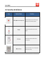
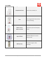
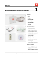
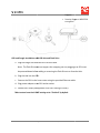
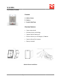
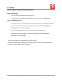
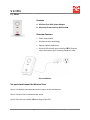
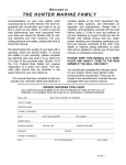
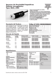
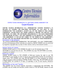
V 2.17t1
Oplink Security
TripleShield
T
Hardware
User Manual
Oplink Communications, Inc.
Oplink Communications, Inc.
1
V 2.17t1
Contents
mi Security At A Glance ................................
...............................................................................................
...............................3
Assemble OPU Station And
nd Connect To Router...................................................
................................
5
Set Up And Power Up
p IP Camera ................................................................
..............................................7
Place Sensors And
nd Power Up Siren ................................................................
...................................... 10
a.) Install the Door/Window
indow Sensor ................................................................
................................................. 10
b.) Motion Sensor................................
................................................................................................
........................................................ 15
c.) Siren ................................
................................................................................................................................
......................................... 17
d.) Sensor Range Extender ................................................................................................
......................................... 18
Appendix A ................................
................................................................................................
................................................... 19
OPU................................
................................................................................................................................
............................................ 19
Dongle ................................
................................................................................................................................
....................................... 20
USB Hub ................................
................................................................................................................................
.................................... 20
Flash Drive ................................
................................................................................................................................
................................ 21
Camera ................................
................................................................................................................................
...................................... 21
Door/Window Sensor ................................
................................................................................................
............................................. 22
Motion Sensor................................
..........................................................................................................................
.......................... 23
Siren................................
................................................................................................................................
........................................... 24
Remote Control ................................
................................................................................................
....................................................... 25
Appendix B ................................
................................................................................................
................................................... 26
FCC Statement................................
................................................................................................
.............................................. 27
Oplink Communications, Inc.
2
V 2.17t1
mi Security At A G
Glance
Item
Product Name
Function
Provide wireless access and control
OPU (Oplink Processing Unit)
function of mi Security system
Transmit sensor data and control
Dongle
signal
Surveillance camera with built-in
built
IP Camera
microphone
Detects and alerts user of movement
Motion Sensor
within the vicinity
Oplink Communications, Inc.
3
V 2.17t1
Door/W
Door/Window Sensor
Use on doors, windows, etc.
etc
Siren integrated with Smart wireless
Siren
security technology
Remote Control
with Panic Button
Arm/Disarm system and emergency
hotline
Additional USB ports to connect
44-port USB Hub
devices to OPU
Extra data storage for video
16
16G Flash Drive
recordings
Oplink Communications, Inc.
4
V 2.17t1
Assemble OPU Station
……………
Station And Connect To Router …………………..
1
Contents
A. OPU
B. Dongle
C. Ethernet Cable
D. Power Adapter
E. 16G Flash Drive
F. USB Hub
Overview Features
• Smart setup wizard
• Bridge the communication
for all Oplink smart devices
• Provide wireless access and
control function of mi
Security system
• OPU allows for system
recovery
• Transmit sensor data and
control signal
• Support Oplink cloud server
Wireless Features
• Support IEEE 802.11 b/g/n
standards
•
Oplink Communications, Inc.
Wired
d and Wireless Network
5
V 2.17t1
Support
•
Security Support: WPA2-PSK
encryption
OPU and Dongle Installation with USB Hub and Flash Drive
a. Plug the Dongle and the Flash Drive into the Hub.
Note: The Flash Drive do
does not support hot swapping nor
or hot plugging. The OPU must
be powered down before adding or removing the Flash Drive to or from the Hub.
Hub
b. Plug the Hub into the OPU.
c. Connect the OPU to the home router using the provided Ethernet cable.
d. Plug power adapter to the OPU and an outlet.
e. Enable DHCP setup (see Appendix B for DHCP setting of router)
router).
*Most routers have their DHCP setting set to “Enabled” by default.
Oplink Communications, Inc.
6
V 2.17t1
Set Up And
And Power Up IP Camera …………………..…..…..…..…..….....
2
Contents
A. Camera
B. Bracket
C. Power Adapter
D. Mounting Screws And Dry Wall Anchor
nchors
Overview Features
•
Smart setup wizard
•
High quality video
•
Built-in antenna and microphone
•
Support Oplink cloud server
•
Day/night vision
• Records automatically when alarms are triggered
•
Remote monitoring from smartphone or tablet
Wireless Features
•
Supports IEEE 802.11 b/g/n standards
•
Wired and Wireless Network Support
•
Security Support: WPA2-PSK
PSK encryption
Oplink Communications, Inc.
7
V 2.17t1
Camera Installation
Set Up the Camera
a. Place the camera within range of a power outlet and co
connect
nnect power cord to the outlet.
b. Connect power adapter to the camera
camera.
Mounting the Camera (Optional)
Note: The camera can also be placed on a table using the bracket provided. We recommend
you placing the camera on a counter
countertop
top giving it a clear line of sight. Infrared night vision makes
it easy to monitor at night.
Step 1: Install camera attachment base
a. At the desired camera mounting location, secure the camera attachment base to the wall
using the provided screws.
b. Make use of the provided screw anchors if necessary.
Oplink Communications, Inc.
8
V 2.17t1
Step 2: Mount the camera
a. Screw camera onto attachment
chment base
base.
b. Secure camera using attachment base nut.
Step 3: Complete the camera’s mount
a. Make sure the camera is firmly fixed on the wall.
b. Adjust the camera to the preferred position.
Oplink Communications, Inc.
9
V 2.17t1
Place Sensors And Power U
Up
p Siren………………………………………
iren………………………………………
3
a.) Install the Door/Window
indow Sensor
Contents
A. Sensor Kit (2 contacts, 1 large unit and 1 small unit)
unit
B. Batteries
C. Double-sided Tape
DWM1300 Overview Features
(for Home Package I)
•
Smart setup wizard
•
Wireless security technology
•
Support Oplink cloud server
•
Apply to doors, windows, etc.
•
Send off instant intrusion alerts
•
Easy to install, no wiring required
•
Auto add-on
on to any Oplink security system
•
Batteries included
Oplink Communications, Inc.
10
V 2.17t1
Sensor DWM1300 Installation
To install the sensors:
1. Install the batteries.
2. Attach the double-sided
sided tape onto the backs of the units
units.
3. Door/Window:
a. On your door:
i. After selecting a location on the door, preferably on the edge of the door
away from the hinges, the large unit of the sensor should be placed on
the immovable frame of the door.
ii. Place the small unit on the movable door with the small arrows on each
unit aligned and not exceeding the recommended width of a pencil or a
quarter of an inch between the sensors for best performance.
b. On your window:
i. After selecting a location on the window, the large unit of the sensor
should be placed on the immovable window frame.
ii. Place the small unit on the movable window with the small arrows on
each unit aligned and not exceeding the recommended width of a pencil
or a quarter of an inch between the sens
sensors
ors for best performance.
4. When you open and close the doors and windows, the two parts should separate when
opened and then come back together when closed.
Oplink Communications, Inc.
11
V 2.17t1
*Note: If your door or window do
does not allow you to properly place the large unit of the
sensor on the frame, it is acceptable to place the smaller unit of the sensor on
n the frame to
make the placing easier.. This is an acceptable approach to sens
sensor placement, although it
should only be used when necessary.
Warning:
Do not dispose of electrical appliances as unsorted municipal waste
waste. Use
se separate collection
facilities. Contact your local government for information regarding the collection systems
available.
DWM1301 Overview Features
(For Home Package II, IV and Business Package I)
•
Smart setup wizard
•
Wireless security technology
•
Support Oplink cloud server
•
Apply to doors, windows, etc.
•
Send off instant intrusion alerts
•
Easy to install, no wiring required
•
Auto add-on
on to any Oplink security system
•
Battery included
Oplink Communications, Inc.
12
V 2.17t1
Sensor DWM1301 Installation
To install the sensors:
1. Install the battery.
2. Attach the double-sided
sided tape onto the backs of the units
units.
3. Door/Window
a. On your door:
i. After selecting a location on the door, preferably on the edge of the door
away from the hinges, the large unit of the sensor should be placed on
the immovable frame of the door.
ii. Place the small unit on the movable door with the small unit aligned near
the top half of the large unit and not exceeding the recommended width
of a pencil or a quarter of an inch be
between
tween the sensors for best
performance.
b. On your window:
i. After selecting a location on the window, the large unit of the sensor
should be placed on the immovable window frame.
Oplink Communications, Inc.
13
V 2.17t1
ii. Place the small unit on the movable window with the small unit aligned
near the top
op half of the large unit and not exceeding the recommended
width of a pencil or a quarter of an inch between the sensors for best
performance.
4. When you open and close the doors and windows, the two parts should separate when
opened and then come back together when closed.
*Note: If your door or window do
does not allow you to properly place the large unit of the
sensor on the frame, it is acceptabl
acceptable to place the smaller unit of the sensor on
n the frame to
make the placing easier.. This is an acceptable approach to sens
sensor placement, although it
should only be used when necessary.
Warning:
Do not dispose of electrical appliances as unsorted municipal waste. Use separate collection
facilities. Contact your local government for information regarding the collection systems
available.
Oplink Communications, Inc.
14
V 2.17t1
b.) Motion Sensor
Contents
A. Motion Sensor
B. Battery
C. Double-sided Tape
Overview Features
•
Smart setup wizard
•
Wireless security technology
•
Support Oplink cloud server
•
Detects motion up to 120-degree, 10-40
40 feet
•
Passive Infrared, Pet immune
•
Battery included
Motion Sensor Installation
Oplink Communications, Inc.
15
V 2.17t1
Set up and wall-mount
mount the motion sensor
Step 1: Insert Battery
a. Lift top tab on cover to release
elease and remove cover.
b. Insert the battery noting the polarity (CR123A), and replace the cover onto the sensor.
Step 2: Install Motion Sensor
a. Place the motion sensor appropriately to ensure maximum coverage of a monitored
area. The motion sensor monitors any movement up to 35 feet and should not be
placed higher than 7 feet from the floor.
b. Use double-sided tape to mount on the wall at the desired location.
c. Make sure the motion sensor is placed
laced at an angle with the least amount of
obstruction for best coverage.
Do not aim the detector at a staircase which a pet has access to.
Do not mount the detector near furniture or objects higher than 4 feet tall which a pet may climb
onto (such as a couch within 6 feet of the detector)
detector).
Oplink Communications, Inc.
16
V 2.17t1
c.) Siren
Contents
A. Wireless Siren With Power Adapter
nchors
B. Mounting Screws And Dry Wall Anchors
Overview Features
•
Smart setup wizard
•
Wireless security technology
•
Support Oplink cloud server
•
Alarm for 60 seconds upon receiving SIREN ON order,
stops immediately upon receiving SIREN OFF order
Siren Installation
Set up and wall-mount the Wireless Siren
Step 1: Use double-sided
sided tape or screws to mount at desired locations.
Step 2: Connect siren to nearest power outlet.
Step 3: Place the siren within effective range of the OPU.
Oplink Communications, Inc.
17
V 2.17t1
d.) Sensor Range Extender
Contents
A. Sensor Range Extender
B. Power Adapter
Overview Features
•
Smart setup wizard
•
Wireless security technology
•
Support Oplink cloud server
•
Transfer legal 433MHz signal
Installation of Sensor Range Extender
Adding the Sensor Range Extender (Optional)
Step 1: Plug the sensor range extender into the adaptor
Step 2: Plug the combination into a power outlet
Step 3: Place the sensor range extender between OPU and sensors. Adjust the distance to make
sure it bridges up the wireless devices so that they would seamlessly roam across to the OPU.
Oplink Communications, Inc.
18
V 2.17t1
Appendix A
Specifications
OPU
Model : OPU1120
Dimensions
Dimensions: 56 mm x 56 mm x 17.3 mm
Operating Temperature
Temperature: 32° F to 113° F (0°
0° C to 40° C)
C
Frequency
Frequency: 2.4-2.4835 GHz
Transmit Speed
Speed: 150Mbps (Max)
Channel
Channel: 13
TX Power
Power: 14dbm, 15dbm(Max)
Storage Temperature
Temperature: -40° F to 158° F (-40°
40° C to 70° C)
Network Protocols
Protocols: DHCP, Auto IP Address
Network Interface
Interface: One 10/100Mbps LAN/WAN
WAN
Interchangeable Port, IEEE 802.3 / IEEE
802.3u
Wireless interface
interface: IEEE 802.11 b/g/n, WPA2-PSK
PSK
Power Adapter
Adapter: 5V 1A
Oplink Communications, Inc.
19
V 2.17t1
Dongle
Model: DGL1130
Dimensions: 83 mm x 27 mm x 9.3 mm
Operating Temperature: 32° F to 113° F (0°
0° C to 45° C)
C
Power Rating: DC5V, 50mA
Frequency: 433.92MHz
Transceiver Mode: Half-duplex
Modulate Type: ASK
Sensitivity: -110dbm
Support hot swapping
USB Hub
Model: HUB1112
Dimensions: 50mm x 50 mm x 22 mm
Weight: 36g
Capacity : 4 USB ports
Communication Standard: USB 2.0
Performance Support: 480Mbps high speed
Operating Voltage: 4.5-5.5VDC
System: Windows/Mac OS
Oplink Communications, Inc.
20
V 2.17t1
Flash Drive
Model: UST1100
Dimensions: 34.6 mm x 12.2 mm x 4.5 mm
Weight: 4.6g
Capacity: 16G
Communication Standard: USB 2.0
Performance: Read:20MB/sec above
Write: 4.5MB/sec above
Operating Voltage
Voltage: 4.5-5.5VDC
System
System: Windows/Mac OS
Operating Temperature
Temperature: 32° F to 113° F (0°
0° C to 45° C)
Storage Temperature
Temperature: -4° F to 158° F ( -20°° C to 70° C)
Camera
Model: IPC1200
Dimensions: 73(L) x 26(W) x 95mm(H)
Operating Temperature
Temperature: 32° F to 113° F (0°
0° C to 45° C)
Video compression: MJPEG
Image resolution: 640 x 480
Storage Temperature: 5° F to 140° F ( -15°
15° C to 60° C)
C
Network Protocols: DHCP, Auto IP Address
Network Interface: 1 Ethernet 10/100BaseT (RJ45) LAN
Oplink Communications, Inc.
21
V 2.17t1
connection
interface: EEE 802.11 b/g/n, WPA2-PSK
Wireless interface
PSK
Power Adapter
Adapter: 5V,1A
Door/Window Sensor
Model
Model: DWM1300
Operating Temperature : 32° F to 113° F (0°° C to 45° C)
Frequency
Frequency: 433.80MHz – 434.1-MHz
Modulation
Modulation: ASK
Transmit Power
Power: > -51dBm(Manufacture’s
51dBm(Manufacture’s test condition)
Detection Type
Type: Magnetic separation trigger function
Magnet Sensor Gap Activated
Activated: ~11mm (Reference)
Power source
source: 1.5V*2pcs“AAA” Lithium and Iron
Disulfide battery
Standby Current
Current: <10uA (@3.3VDC)
Operating Current
Current: <18mA (@3.3VDC)
Battery Low Level Indicator
Indicator: 2.2V-2.4V
Low Battery Alarm Mode
Mode: Low battery alarms
rms only when
another sensor alarm is triggered
Unpick Detectio
Detection: Tamper switch wireless alarm
Oplink Communications, Inc.
22
V 2.17t1
Model: DWM1301
Operating Temperature: 32° F to 113° F ( 0°° C to 45° C)
Frequency: 433.92MHz +/-150KHz
Modulation: ASK
Transmit Power: >= -16dBm(Manufacture’s
16dBm(Manufacture’s test condition)
Detection Type
Type: Magnetic separation trigger function
Magnet Sensor Gap Activated
Activated: ~25mm (Reference)
Power source
source: CR123A 3V
Current: <3uA
Standby Current
Current: <=15mA
Operating Current
Indicator: 2.1 V-2.35V
Battery Low Level Indicator
Mode: Low battery alarms only when
Low Battery Alarm Mode
another sensor alarm is triggered
Unpick Detection
Detection: Tamper switch wireless alarm
Motion Sensor
Model: PIR1301
Operating Temperature: 14° F to 122° F ( -10°
0° C to 50° C)
C
Frequency: 433.92 MHz +/- 150KHz
Transmit Power: >= -16dBm(Manufacture’s
16dBm(Manufacture’s test condition)
Modulation: ASK
Oplink Communications, Inc.
23
V 2.17t1
Power Source
Source: CR123A 3V
Current: <25uA
Standby Current
PIR Trigger Current
Current: <=15mA
Power Consumption
Consumption: 1 year (Triggered twice a day)
Battery Low Level Indicator
Indicator: 2.1 V-2.35V
Low Battery Alarm Mode
Mode: Low battery alarms
arms only when
sensor alarm is triggered
PIR Trigger Alarm
Alarm: Once Motion Sensor alarms, it will start to
count 3 minutes, and start over again iff any movement is
detected within this period. The next alarm will be triggered
only when no movement is detected within the 3 minutes.
Unpick Detection
Detection: Tamper switch wireless alarm
Siren
Model
Model: SRN1300
Operating Temperature
Temperature: 32° F to 113° F (0°
0° C to 40° C)
De
Device Type: Wireless Indoor Siren
RF Receiver Frequency: 433.92 MHz +/- 0.125MHz
Sensitivity
Sensitivity: -110dbm
Modulation
Modulation: ASK
Power Source
Source: Main Power-AC
AC Adaptor (American Standard);
Standard)
Backup Battery-Alkaline
Alkaline battery “AAA”size * 3pcs
Standby Mode Current
Current: ≤12mA(average) @4.5V
Alarm Mode Current
Current: <[email protected]
Oplink Communications, Inc.
24
V 2.17t1
Alarm Sound Level
Level: >=110dB(@30cm
dB(@30cm on desktop 4.5V Power
Remote Control
Model
Model: RMC 1300
Power: A23, 12V Battery
Power Consumption: >1year (Triggered
Triggered twice a day)
day
Button: “ARM”, ARM ON mode
“OFF”, ARM OFF mode
“Hotline”, Panic Button
Operating Environment: 32° F to 113° F (0°
0° C to 40° C)
Storage Temperature: -4° F to 159 ° F (-20°
0° C to 65° C)
RF Frequency
Frequency: 433.92 MHz +/- 0.13MHz
Modulation
Modulation: ASK
Transmit P
Power: -55dBm+/-4dBm
Oplink Communications, Inc.
25
V 2.17t1
Appendix B
DHCP (Dynamic Host Configuration Protocol) setting of router
Fig.1 DHCP Setting of Router (E
(Example of Router: 2wire 2701HG-B)
(1) Open a browser and enter your IP address, such as”192.168.X.X”. You can find this address
on the back of the router.
(2) Log in to your router’s account. Check your user manual or documentation if you do not
know the log-in credentials.
(3) Make sure you are in the Setup category
category, select 'Enable DHCP' and enter the address range
(from “192.168.1.100” to “192.168.1.199”).
Oplink Communications, Inc.
26
V 2.17t1
FCC Statement
1. Warning: Changes or modifications to this unit not expressly approved by the party responsible
for compliance could void the user’s authority to operate the equipment.
NOTE: This equipment has been tested and found to comply with the limits for a Class B digital
device, pursuant to Part 15 of the FCC Rules. These limits are designed to provide reasonable
protection against harmful interference in a residential installation. This equipment generates,
uses and can radiate radio frequency energy and, if not installed and used in accordance with the
instructions, may cause harmful interference to radio communications.
However, there is no guarantee that interference will not occur in a particular installation. If this
equipment does cause harmful interferenc
interference
e to radio or television reception, which can be
determined by turning the equipment off and on, the user is encouraged to try to correct the
interference by one or more of the following measures:
Reorient or relocate the receiving antenna.
Increase the separation
paration between the equipment and receiver.
Connect the equipment into an outlet on a circuit different from that to which the
receiver is connected.
Consult the dealer or an experienced radio/TV technician for help
help.
2. This device complies with Part 15 of the FCC Rules. Operation is subject to the following two
conditions:(1)
(1) this device may not cause harmful interference, and (2) this device must accept
any interference received, including interference that may cause undesired operation.
3. Shielded cables must be used with this unit to ensure compliance with the Class B FCC limits.
Oplink Communications, Inc.
27