1
HelpAndManual_unregistered_evaluation_copy
VQDM-100
AV Test Pattern Generator
____________________
AV Delay & Sync Analyzer
Version 1.1.6
User Manual
HelpAndManual_unregistered_evaluation_copy
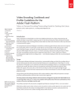
VQDM-100
AV Test Pattern Generator and AV Delay & Sync Analyzer
by VideoQ Inc
Compact Tool to evaluate and measure the quality and timing of
processed and displayed video.
Advanced test patterns instantly revealing your video procesor
and/or display device performance.
Built-in multi-channel audio & video delays analyzer measures
absolute and relative AV delay parameters.
HelpAndManual_unregistered_evaluation_copy
VQDM-100 User Manual
© 2010-2011 by VideoQ Inc, all rights reserved
All rights reserved. No parts of this work may be reproduced in any form or by any means - graphic, electronic, or
mechanical, including photocopying, recording, taping, or information storage and retrieval systems - without the
written permission of the publisher.
Products that are referred to in this document may be either trademarks and/or registered trademarks of the
respective owners. The publisher and the author make no claim to these trademarks.
While every precaution has been taken in the preparation of this document, the publisher and the author assume no
responsibility for errors or omissions, or for damages resulting from the use of information contained in this
document or from the use of programs and source code that may accompany it. In no event shall the publisher and
the author be liable for any loss of profit or any other commercial damage caused or alleged to have been caused
directly or indirectly by this document.
Author: Victor Steinberg
Printed: May 2012 in Santa Clara, California, USA
Special thanks to:
Michael Shinsky, Maria Rozen and Mikhail Budchenko,
who contibuted to this product development
Revision History
Revision Date
Description
1.1.0
2010, May
RC 1
1.1.1
2010, November
Release
1.1.2
2011, January
Release
1.1.3
2011, September Release
1.1.4
2011, November
Release
1.1.5
2012, February
Release
1.1.6
2012, May
Release
VQDM-100 User Manual
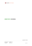
Table of Contents
1 Introduction
..............................................................................................................
and Overview
2
2 Front..............................................................................................................
Panel & Rear Panel
7
3 VQDM
..............................................................................................................
Test Patterns Description
8
4 Software
..............................................................................................................
Installation
11
5 Test..............................................................................................................
Pattern Generator Module
12
5.1 Operation
....................................................................................................................... 14
5.2 Configuration
and Customization
.......................................................................................................................
17
6 VQHD420
..............................................................................................................
Adapter
20
7 Test..............................................................................................................
Environment and Setup
22
8 VQDM
..............................................................................................................
Analyzer Software
27
8.1 Main Window
....................................................................................................................... 28
8.2 Menus....................................................................................................................... 31
8.2.1 Menu
.................................................................................................................................................
- File
31
8.2.2 Menu
.................................................................................................................................................
- View Page
31
8.2.3 Menu
.................................................................................................................................................
- Help
32
8.3 Control.......................................................................................................................
Panel Window
34
8.4 Command
Line Mode
.......................................................................................................................
38
8.5 Short Report
Samples
.......................................................................................................................
40
8.6 Configuration
.......................................................................................................................
File Sample
45
9 Test..............................................................................................................
Session Setup
46
10 Saleae
..............................................................................................................
'Logic' Software Usage
48
11 Specifications
.............................................................................................................. 50
© 2010-2011 by VideoQ Inc, all rights reserved
VQDM-100 User Manual
1
Introduction and Overview
2
Introduction and Overview
VQDM is a multi-functional tool for video systems installers, development labs, software
developers and high volume manufacturers – to test cameras, displays, codecs, transcoders, players
and complex video systems, e.g. teleconference systems.
It consists of Test Generator Module, Data Acquisition Module and Delay Analyzer
Software.
In combination, they provide for accurate measurement of Video Latency, Audio Latency, AV
Sync Errors and Frames Continuity Testing.
Data Acquisition Module has 4 video inputs and 4 audio inputs. All relevant Test Points of the
System Under Test should be connected to the appropriate VQDM inputs:
any video input can be connected to the special Light Sensor;
any audio inputs can be connected to standard audio line signal.
Optional VQHD420 adapter unit converts HDMI/DVI signal to Sync Pulse sequence suitable for
VQDM video inputs, thus replacing Light Sensor pulse sequence.
Easy-to-use GUI reveals multi-channel delay profiles, delay statistics, and AV sync errors in real
time; analysis results are updated every 10 seconds.
Test Pattern Generator module provides for calibration and pre-qualification of System Under
Test using built-in subset of VQL - VideoQ Test Patterns Library, which allows triple usage:
visual-aural, instrumental and fully automated.
All necessary test pattern files in a variety of resolutions and formats are permanently stored in the
TPG internal memory together with brief tutorials in slide-show format.
Analysis of video/audio quality is performed by visual-aural evaluation, by running 3rd party tools
or by running VideoQ Analyzers, such as VQMA.
VQL test patterns,including special VQDM test patterns, are available in 2D and 3D versions and
in several source options:
· HDMI signal from TPG module - to test displays and cameras
· Uncompressed YUV Files - to test codecs
· Compressed Transport Stream Files - to test transcoders and decoders
VQDM delay measurement methodology is based on specially designed sophisticated dynamic
VQDM Test Patterns.
Test patterns components are designed to be compatible with a majority of video cameras,
software or hardware codecs and media players. VQDM test patterns contain only relatively large
components, so they remain suitable for accurate measurements even after low bitrate coding and
severe position and/or scaling errors, e.g. zoom-out down to 25% or overscan up to 110%.
VQDM tests are available in a variety of frame rates (as labeled on the test pattern); flashes
duration and general layout may vary.
© 2010-2011 by VideoQ Inc, all rights reserved
3
VQDM-100 User Manual
Introduction and Overview
VQDM Analyzer can work with either one of two test patterns: VQDM1 (also called VQDM)
and VQDM2-1.
VQDM1 test pattern shown below allows automatic measurement of AV delays and visual
estimation of frame continuity errors.
It is suitable for automatic glass-to-glass testing of camera-link-display systems, e.g. video
conference systems.
Two large Light Sensor Areas on the Test Pattern are flashing white every second for the
duration of two video frames.
These flashes are read for analysis purposes by VQDM Light Sensors fitted attached to the
display screen by vacuum caps.
This allows testing cameras and displays of any resolution and frame rate; perfect (i.e.
time-consuming) setting of zoom/position/focus is not required. Average picture level of the
VQDM1 test is approximately mid-gray, thus allowing normal camera operation in auto-iris mode.
Orbiting White Dot serves as Motion Continuity (Frames Continuity) test; any non-uniformity in
the appearance of its motion means frame drop/freeze. Highly visible Time Stamps (frame
numbers) in the central area are especially useful for off-line frame-by-frame analysis of recorded
video data.
Such self-contained glass-to-glass solution allows measurement in normal work conditions without
any interference into the System Under Test.
Audio delays are measured similarly - by connecting relevant test points to the corresponding
VQDM outputs and inputs. There is no need for special audio sensors, VQDM TPG Module
produces and VQDM Data Acquisition Module read standard audio line signals.
VQDM2-1 test pattern shown below also allows measurement of AV delays and frame continuity
errors.
It is suitable for manual and automatic testing of signal-to-signal systems, such as video
contribution links, and signal-link-display systems, e.g. IPTV systems.
© 2010-2011 by VideoQ Inc, all rights reserved
VQDM-100 User Manual
Introduction and Overview
4
Important feature of VQDM2-1 dark yellow background with yellow texts and markers is that it
produces 0% signal in Blue channel.
Four large Light Sensor Areas on the Test Pattern are flashing white every second. These flashes
are read for analysis purposes by VQDM Light Sensors attached to the display screen.
Sensor Areas Sets A1/A2 and B1/B2 serve for measurement of glass-to-glass system latency, and
AV sync errors; with reference to A1/A2 the set B1/B2 allows measurement of display latency
vertical profile.
Narrow BluSync stripe flashing 100% Blue synchronously with Areas A1/A2 serves to measure
display latency using optional HDMI-to-Sync adapter
Note that VQHD420 adapter operation relies on the blue flashes within VQDM2 test pattern;
VQHD420 is not compatible with VQDM1 test.
Frames Continuity Sensor Areas C1 and C2 are flashing Black-Yellow: 2 video frames each area,
sequence period = 4 frames. Any change of this cadence can be easily seen:
· on the System Under Test display screen
· observing the VQDM front panel green LED flashes cadence
· on the VQDM software scope displaying captured sequence of C1, C2 Light Sensor pulses
VQDM main unit, housed in the compact light metal enclosure, contains two modules:
· TPG - Test Pattern Generator
TPG module setup, work modes and content file selection are performed via on-screen menus
and compact remote control unit.
· DAM - Data Acquisition Module powered from TPG module and communicating with host PC
via USB cable
DAM module has 4 video inputs and 4 audio inputs.
Valid audio and video inputs are indicated by two corresponding groups of green LEDs
flashing every second, independent of Host PC or software analyzer status.
TPG and DAM modules work independent of each other, so they can be used together or
separately - as described in the following sections.
Supplied light-weight carry case contains main VQDM unit with all necessary accessories, such as
light sensors, cables, adapters, etc.
© 2010-2011 by VideoQ Inc, all rights reserved
5
VQDM-100 User Manual
Introduction and Overview
Delay Analyzer Software (VQDM.EXE) runs under Windows OS.
The program process in real-time 100 kBps data stream, acquired by VQDM main unit and
transferred to host PC via USB cable.
VQDM.EXE can be run in two modes:
· Windows GUI Mode suitable for design labs and general setup
· Command Line Mode suitable for automated applications (background process)
In Windows GUI Mode two types of Reports are simultaneously available:
· Machine-readable Test Report file for test automation QA/QC applications
· Detailed Test Summary Table and corresponding PDF document for engineers
In Command Line Mode only machine-readable Test Report file is created.
Picture below shows setup example for Teleconference System video latency measurement:
In this example glass-to-glass latency measurement covers complete system:
Camera + Coder + Network + Decoder + Display-2.
© 2010-2011 by VideoQ Inc, all rights reserved
VQDM-100 User Manual
Introduction and Overview
VQDM Carry Case Content:
- Main Unit
- PSU
- Remote Control
- Light Sensors in plastic containers, x4
- 2 m (9') stereo mini jack cables with numbered labels, x4
- AV cables of two types:
YPrPb component
CVBS plus LR audio
- USB cable, A-B type
© 2010-2011 by VideoQ Inc, all rights reserved
6
7
2
VQDM-100 User Manual
Front Panel & Rear Panel
Front Panel & Rear Panel
Front Panel Status Indicators
· MEM indicator (dimmed blue) shows status of both internal and external memories.
It is always lit during normal operation; flashes few seconds on power-up and connection to
external memory device.
· PWR indicator (dimmed blue) is always lit during normal operation.
· Eight green LEDs at the bottom are flashing green showing active video/audio channels
Rear Panel Connectors
Top row connectors - TPG Module:
· YPrPb - analog video output, mini-jack to 3xRCA cable included
· AV - Y/C (S-video) and CVBS (NTSC/PAL) outputs, mini-jack to 3xRCA cable included
· LAN - RJ45, 10/100 Ethernet network
· SPDIF - digital audio (optical) output
· HDMI - main TPG video/audio output, recommended for VQDM Test Pattern play-out
· USB - type A, play-out of additional content from external storage device
· PWR - external power supply adapter input, 12 V, 1.5 A, center = positive
Bottom row connectors - DAM Module:
· PC - USB type B, connection with Host PC, mini-jack cable included
· Video 1-4 - mini-jacks, connection with Light Sensors, labeled mini-jack cables included
· Audio 1-4 - mini-jacks, connection with Audio Test Points, cables and adapters not included
© 2010-2011 by VideoQ Inc, all rights reserved
VQDM-100 User Manual
3
VQDM Test Patterns Description
8
VQDM Test Patterns Description
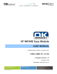
Picture below shows VQDM1 Test Pattern composition:
The dynamic test pattern consists of:
· Highly visible time stamps (frame numbers) in the central area
· Synchronously rotating white dot (clock dial)
· Normally black circular Light Sensor Areas flashing 100% White
on Video Frames #-01 and # 00
· Sliding white ellipse marker indicating current frame position within the +/- 500 ms timeline
scale; position “0” marks the center of Audio Burst
VQDM test pattern is available in a variety of frame rates. Source Frame Rate labeled on the test
pattern itself may differ from Display Frame Rate.
Displayed frame number range and dial layout may also vary depending on the video signal format.
3D version differs from 2D version only in the configuration of Light Sensor Areas:
· 2D version – each frame contains two symmetrically positioned Light Sensor Areas
· 3D version – each of Left and Right images contains only one Light Sensor Area, allowing:
- automatic Left/Right Channel Identification
- automatic LR Sync Error Measurements
VQDM 3D test pattern files are available in 2 variants:
· L & R separate channels, full size
· LR channels combined side-by-side, full height
© 2010-2011 by VideoQ Inc, all rights reserved
9
VQDM-100 User Manual
VQDM Test Patterns Description
Picture below shows 3D Test Pattern composition:
Picture below shows details of VQDM1 Test Pattern audio component:
The audio burst central gap can be used as a precise time stamp for very accurate audio timing
measurements whilst using waveform monitor or AV editing software.
This 1 ms long central gap is ignored by VQDM Delay Analyzer Software, which relies only on
audio burst "center of gravity" position.
Such approach allows VQDM to provide reliable audio delay measurement even on severely
distorted signals.
© 2010-2011 by VideoQ Inc, all rights reserved
VQDM-100 User Manual
VQDM Test Patterns Description
10
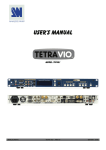
Picture below shows VQDM2-1 Test Pattern composition:
The dynamic test pattern consists of:
· Dark yellow background producing 0% signal in Blue channel
· Normally black circular Light Sensor Areas A1/A2 and B1/B2 flashing 100% White every
second
· Narrow BluSync stripe flashing 100% Blue synchronously with Areas A1/A2
· Variable width Frames Continuity Stripes flashing 75% and 100% Blue synchronously with
Areas C1/C2
· Sliding yellow ellipse marker indicating current frame position within the +/- 500 ms timeline
scale; position “0” marks the center of Audio Burst
· Frames Continuity Sensor Areas C1 and C2 flashing Black-Yellow with 2:2 cadence
Audio component of VQDM2-1 test pattern is the same as VQDM1.
© 2010-2011 by VideoQ Inc, all rights reserved
11
4
VQDM-100 User Manual
Software Installation
Software Installation
1. Install Saleae Logic software and driver - follow on-screen instructions.
Do not connect USB cable until the end of this stage!
2. Connect Host PC with VQDM main unit - plug-in the USB cable.
It is possible, though it is not required, to test connectivity by launching Saleae Logic executable.
If Logic Analyzer Title Bar shows "Connected" message, then USB cable and the driver work
correctly. Important: shut down Logic executable after this test.
3. Install VQDM software as follows:
Create a folder on the PC hard drive, for example "c:\VQDM", and copy there the following files:
a) VQDM.EXE - Main executable
b) SaleaeDeviceSdk.dll - Driver library for DAM hardware
Removing VQDM software is quite simple.
1. Uninstall Saleae Logic software thru Windows Start Menu or Windows Control Panel
2. VQDM.EXE does not make records in Windows system registry, except the location of the last
opened files. Therefore, to remove VQDM from the system it is enough to delete the executable
files VQDM.EXE and SaleaeDeviceSdk.dll.
© 2010-2011 by VideoQ Inc, all rights reserved
VQDM-100 User Manual
5
Test Pattern Generator Module
12
Test Pattern Generator Module
TPG module consists of a media player platform loaded with sophisticated video and audio content
- set of static and dynamic test patterns in a variety of formats - up to 1080p60.
The TPG module is based on Western Digital "WD TV Live" media player platform.
It is supplied complete with pre-installed audio-video content.
No additional software installation is required for normal system operation.
VQDM system relies on VQL - the unique VideoQ Test Pattern Library.
The sub-set of VQL patterns loaded into VQDM TPG is described in a separate document.
Additional test patterns or any video/audio/static image content files of compatible formats can be
played-out thru rear panel USB or RJ45 (network) connectors.
Navigation is easy - thru straight forward folders and files with Remote Control. The most often
used pattern, such as VQDM Test Pattern are in the root folder, which is a default location, when
VQDM is powered on.
VQDM TPG module is equipped with digital HDMI and SPDIF outputs plus baseband analog
YPrPb and NTSC/PAL CVBS video outputs as well as analog L-R audio outputs.
This model does not support 3G or HD-SDI output formats.
However the signals in these formats, can be produced by connecting the VQDM-100 HDMI
output to any suitable HDMI-to-SDI converter.
© 2010-2011 by VideoQ Inc, all rights reserved
13
VQDM-100 User Manual
Test Pattern Generator Module
TPG connectors are in the upper row on VQDM rear panel:
Main TPG Features:
· HDMI 1.3 output, switchable YUV/RGB format:
- YUV output level scheme is always 16-235
- RGB level scheme is switchable: 16-235 ("RGB Low") or 0-255 ("RGB High")
· Multi-format SD and HD playback:
- [email protected], 576p@50, 720p@50, 720p@60
- 1080i@50, [email protected], 1080p@24, 1080p50, [email protected]
· Major Video Codecs/Formats: MP2, MP4, H264/AVC, VC1; AVI, MP4, VOB, TS, M2TS
· Major Audio Codecs/Formats: WAV, AAC, AC3, MP3
· SPDIF 5.1 Digital Audio
· Analog Audio (L & R ) out (mini-jack)
· Auxiliary analog YPrPb output (mini-jack)
· Auxiliary CVBS output, NTSC/PAL (mini-jack)
· Flexible pixels mapping and scaling:
- No scaling (dot-by-dot), if file resolution matches native HDMI resolution
- Up- and down- scaling to match the HDMI resolution, if AutoScaling = On
© 2010-2011 by VideoQ Inc, all rights reserved
VQDM-100 User Manual
Test Pattern Generator Module
14
5.1 Operation
VQDM TPG is supplied fully configured with all settings in the correct positions.
However, it is highly recommended to check the set-up as described in "Configuration and
Customization" section.
To select the desired content for play-out use the remote control - browse folders tree and find the
content file name.
Different types of content are accessible after choosing the corresponding menu:
· Static or Dynamic VQL test patterns and live clips are accessible via "Video" menu.
· Static photos and slide-shows are accessible via "Photo" menu.
· Audio test patterns are accessible via "Music" menu.
In each of these modes not all folders are visible - only the folders with the content of the selected
type.
For example, in "Photo" mode only the folders containing static pictures are visible, other folders,
e.g. containing only video files or only audio files are hidden.
Picture below shows all folders with all types of the pre-loaded VQL content.
Numbered folders are sorted by categories.
This picture serves for information only and it is not displayed on-screen; folders structure may
vary depending on release version.
Each of numbered folders contains a tree of sub-folders with relevant test patterns, typically
further sorted by resolutions.
© 2010-2011 by VideoQ Inc, all rights reserved
15
VQDM-100 User Manual
Test Pattern Generator Module
Patterns of particular resolution with different frame rates (if available) usually located in the
same folder.
There is one special folder:
"00 VQDM - Latency, Continuity and AV Sync Tests"
It contains two important dynamic test patterns required by VQDM Analyzer software: VQDM1
and VQDM2.
The folder "10 VQDM100 Brief Presentation (Slide-Show)" contains a brief of VQDM-100 User
Guide.
The folder "11 VQL - VideoQ Test Patterns Library (Slide-Show)" contains a Short Guide for the
most important test patterns and their features.
To access these two folders and to watch the slide-shows the TPG module should be switched into
"Photo" mode
Important Note:
For truly objective evaluation of the display device performance the internal VQDM-100 scaler
should be bypassed, i.e. neither spatial nor temporal internal scaling should be applied.
It means that HDMI resolution, interlace mode and frame rate should be set exactly matching the
media content file parameters.
For example, the appropriate 1080i60 HDMI mode should be selected via submenu
"Settings/Audio-Video/Display Resolution" before playing out "VST 1080i 60" test pattern .
Once selected, the HDMI mode is preserved, even when the VQDM-100 is switched on/off by the
Remote Control "Power" button.
However, if the external PSU or main supply line is disconnected, the unit may return to HDMI
"Auto" (safe) mode, which is the lowest resolution available for this particular display. In such case
the submenu "Settings/Audio-Video/Display Resolution" should be re-visited to set or restore the
desired HDMI mode.
© 2010-2011 by VideoQ Inc, all rights reserved
VQDM-100 User Manual
Test Pattern Generator Module
16
Below is brief description of Remote Control functions
"Option" button is important because it enables OSD messages and menus, in particular - media
info, pan & zoom controls, repetition mode (play once, repeat same file, repeat all files in the
folder), etc. This button works as on/off toggle switch.
For full description of Remote Control keys and functions, navigation instructions and complete
list of on-screen menus see separate document "WD TV Live User Manual.pdf".
© 2010-2011 by VideoQ Inc, all rights reserved
17
VQDM-100 User Manual
Test Pattern Generator Module
5.2 Configuration and Customization
Recommended TPG Settings
From "Home" page select "Settings/Audio/Video" menu
Audio/Video Menu Settings
Use the menus in this category to configure playback for audio and video files. Set the following:
Video Output:
When using an HDMI cable, select HDMI in the Video Output screen. You will be prompted to
select the applicable HDMI video resolution for your device. Make your selection and press
ENTER.
In the Display Resolution sub-menu below "Auto" means "safe mode", i.e. the lowest available
resolution, which is seldom needed.
After the unit is powered on first time and "Home" menu appears on screen (in small size),
"Audio-Video/Display resolution" should be changed to native display resolution, interlace and
frame rate, e.g. 1080p60.
© 2010-2011 by VideoQ Inc, all rights reserved
VQDM-100 User Manual
Test Pattern Generator Module
18
Aspect Ratio:
Select "Widescreen" (default, i.e. typical native 16:9 display option)
"Normal" here means 4x3 display aspect ratio, which is seldom needed.
Important: In the "Settings/Audio-Video" sub-menu selection of "Composite" instead of "HDMI"
disables HDMI output and vice versa. This selection should be taken with caution because for
few seconds the menus will be visible only on the display connected to "CVBS" output. On the
other hand, VQDM-100 automatically detects connections to HDMI and CVBS outputs, so once
the HDMI output is disconnected the CVBS output is automatically enabled (if connected) overriding the menu settings. Consequent disconnection of CVBS output automatically restores
HDMI output.
Important: In Settings/Audio-Video" menu the selection of "Stereo" as an audio output disables
digital SPDIF output, but if "Digital" audio output is selected, the analog stereo output may be still
present. In the latter case all L+R stereo formats and some types of 5.1 surround sound content
(not all formats) can played on both digital and analog output, but on analog output 5.1 content is
converted to L+R (down-mix).
Selection of NTSC/PAL in "Settings/Audio-Video" sub-menu affects only the format of auxiliary
analog CVBS output, it does not affect HDMI output.
HDMI Deep Color:
Select 8 bit (this is the "safest" option)
Audio Output:
Select "Stereo" (HDMI digital stereo audio will be still available)
Alternatively, select "Digital" - only if you are using an Toslink (optical) connection to output
surround sound.
© 2010-2011 by VideoQ Inc, all rights reserved
19
VQDM-100 User Manual
Test Pattern Generator Module
Photo Menu Settings
In the "Settings/Photo" sub-menu "Keep as original" option is recommended because it prevents
unwanted scaling (distortion) of photo images.
System Settings/Browser Display Menu Settings
In the "System Settings/Browser Display" menu select "List mode", because it allows navigation
via folders and long file names.
Selection of "Thumbnails mode" is not recommended because the current version of VQDM-100
system does not support navigation by thumbnails.
© 2010-2011 by VideoQ Inc, all rights reserved
VQDM-100 User Manual
6
VQHD420 Adapter
20
VQHD420 Adapter
Optional VQHD420 adapter module is based on Atlona AT-HD420 HDMI to VGA/YPrPb and
Stereo Audio Format Converter.
VQHD420 converts HDMI to a VGA or component output.
VQHD420 unit is fitted with Blue channel video level comparator outputting BluSync Pulse signal
compatible in voltage and impedance with the VQDM Light Sensor signal.
This pulse is available on a mini-jack socket next to VGA output connector. BluSync Pulse
Activity is indicated by flashing green LED located on the right.
Output video format is selected by VGA/COMPONENT switch. VQHD4200 VGA output can be
used for preview/monitoring purposes or left idle (not connected). For YPrPb output special VGA
to 3 RCA adaptor cable (supplied) could be used, but BluSync output will be disabled.
Warning: BluSync Pulse output is available only if the VQDM2 Test Pattern is running and
VQHD420 format switch is in the VGA position.
HDMI formats supported by VQHD420 in BluSync mode are:
720: p50, p59.94, p60
1080: i25, i29.97, p50, p59.94, p60.
VQHD420 converter is always de-embedding audio from the HDMI source and converts it to an
analog stereo 1/8-inch interface. This will allow the user to connect it to any audio input of main
VQDM unit, a set of speakers or any other audio device.
Typically, VQHD420 BluSync output should be connected with VQDM100 Video Reference
input and VQHD420 Audio output should go to VQDM100 Audio Reference input.
© 2010-2011 by VideoQ Inc, all rights reserved
21
VQDM-100 User Manual
VQHD420 Adapter
Test setup with VQHD420 adapter and vacuum cap sensor attached to the display screen allows
display latency measurement.
Test setup with two or more VQHD420 adapters allows latency measurement without any
vacuum cap sensors. Setup without any vacuum cap sensors is preferable for very long test
sessions or for fully automated codec/network latency tests; in such case first adapter BluSync
output is connected to VQDM V1 (Video Reference) input, second adapter BluSync output is
connected to VQDM V2 input, and so on.
Embedded EDID simplifies the installation procedure. The VQHD420 sync up with the source and
let the source know to start outputting RGB or YPrPb format depending on the output selection
and also switch audio to stereo or PCM.
VQHD420 is HDMI 1.2 and DVI (HDMI to DVI adapter required) compliant, i.e. it can convert
HDMI or DVI to VGA or component video.
Note 1. VQHD420 is a format converter only; the converter is not capable to scale the image and
therefore it is very important to select the proper HDMI source resolution.
Note 2. VQHD420 does not support HDCP decryption; if an HDMI source includes HDCP (Highbandwidth Digital Content Protection) there will be no output image displayed.
© 2010-2011 by VideoQ Inc, all rights reserved
VQDM-100 User Manual
7
Test Environment and Setup
22
Test Environment and Setup
Test setup consists of connecting all relevant Test Points to the appropriate VQDM inputs located
on the rear panel :
Step 1: Connect USB port with Host PC.
Important: DAM module is powered from external PSU (not from USB port), so all following
steps require VQDM100 power adapter to be switched ON.
Step 2: Displays, Camera and Light Sensors Setup
Picture below shows setup example for Teleconference System video latency measurement using
VQDM1 test pattern:
In this example glass-to-glass latency measurement covers complete system:
Camera + Coder + Network + Decoder + Display-2.
Connect reference display to the VQDM test pattern source, typically to the HDMI output of the
TPG module.
© 2010-2011 by VideoQ Inc, all rights reserved
23
VQDM-100 User Manual
Test Environment and Setup
Point the camera to this display and adjust camera's pan, tilt and zoom controls to get best
possible fit of the display screen.
Vertical position errors are critical, so proper centering is important.
Horizontal and vertical size errors up to 10% are acceptable.
Attach video sensors to display screens - as many as required by the test plan.
For example, if the reference screen sensor is attached within the right flashing circle, then all
other sensors (attached to other displays, i.e. to other Test Points) should be installed in the not
obscured (i.e left) flashing circle.
It is highly recommended to clean sensor vacuum cap and the screen target area with wet LCD
cleaning wipe - immediately before each sensor installation.
A bit of moisture left on the edges of vacuum cap provides for much longer vacuum preservation,
especially on mat screen having not so smooth surface.
This is particularly important for tests of large duration - more than 10 minutes.
Warning: Large amount of cool liquid put on hot screen surface may damage screen or kill screen
pixels, so necessary precautions should be taken.
Vertical position of the sensor in the flashing circle directly affects the measurement accuracy.
Vertical sensor shift from flashing circle center to the circle edge may offset measured delay value
up to 3-4 ms.
Horizontal position is of smaller importance, but proper centering is still desirable because it means
better sensitivity.
Screen brightness should be set high enough to drive sensors properly.
Because many LCD displays use pulse-width modulation technique to control back-light intensity
it is highly recommended to use maximal display brightness, thus minimizing the detrimental effect
of back-light modulation.
On the other hand, VQDM automatically adjusts slicing level - separately for each light sensor, so
it can work within very wide range of screen luminosities.
Black level is of smaller importance, but better keep it dark enough. Black areas brightness values
between 0% and 20% are acceptable.
Compression coding artefacts (blockiness) may deteriorate sensor function, but only if the artefact
contrast is very high - more than 25%.
© 2010-2011 by VideoQ Inc, all rights reserved
VQDM-100 User Manual
Test Environment and Setup
24
Step 3: Connect video inputs.
Connect by mini-jack cables at least two video inputs to the Light Sensors attached to displays
showing VQDM Test Pattern.
It is highly recommended to connect VQDM Video Reference (V1) input to the Light Sensor
attached to display getting "clean" video directly from VQDM main unit HDMI output.
Other video channels can be connected in arbitrary order, e.g. V2 and V4 are activated, but Input
V3 is idle (not connected).
Warning: VQDM DAM module requires about 20-30 seconds to reach steady state condition after
any video cable connection or re-connection (light sensor <=> VQDM video input).
Thus, some waiting time is necessary to get accurate reading of front panel indicators and analysis
results. Note that re-location of light sensors between different screen areas requires much shorter
waiting time - typically few seconds.
Step 4 (optional): Connect audio inputs.
This connection is mandatory only if Audio Delays and/or AV Sync Errors should be measured.
Rules for audio inputs are similar to those for video inputs. At least two audio inputs, including
Audio Reference, must be connected.
It is highly recommended to connect Audio Reference input directly to one of two (L & R) audio
outputs of VQDM main unit.
Other schemes are also possible, e.g. VQDM Audio Reference input can be connected to the
headphone output of TV set, receiving both video and audio from VQDM HDMI output.
If Audio Reference or other audio channel input is not valid, then only VQDM Audio Results
(including AV Sync) are invalidated, but video delay measurements are still valid.
To measure AV Sync parameters it is recommended to use Video Reference (V1) and Audio
Reference (A1) inputs, however it is possible to use other pairs of inputs.
There is only one parameter, which requires both A1 and V1 inputs to be connected and valid. It
is current time offset between A and V References, displayed on a Summary Page. It provides for
fast estimation of A-V Reference Inputs relative delay. This parameter is for guidance only and it
does not affect any other measurements results.
Step 5: Launch VQDM.EXE application and follow 'VQDM Analyzer Software' section
instructions.
Validity of video/audio inputs is confirmed by VQDM front panel LEDs and also by VQDM.EXE
main window indicators.
© 2010-2011 by VideoQ Inc, all rights reserved
25
VQDM-100 User Manual
Test Environment and Setup
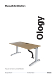
Picture below shows example of typical Timing Diagram of VQDM outputs and inputs:
On this diagram two Systems are tested in one VQDM Test Session.
Video inputs V1, V2 and V3 are connected to corresponding Light Sensors.
Audio input A1 is connected to TPG audio output, inputs A2 and A3 are connected to audio Test
Points.
Note that Audio Reference time moment is taken directly from TPG output, but Video Reference
on this diagram is not the TPG output, but Monitor A Sensor Signal.
A/V Sync Errors of two systems are calculated as two differences:
A/V Sync Error 1 = Audio Latency 1 – Video Latency 2
A/V Sync Error 2 = Audio Latency 2 – Video Latency 2
Note that in each system video and audio latencies are measured separately and independently.
© 2010-2011 by VideoQ Inc, all rights reserved
VQDM-100 User Manual
Test Environment and Setup
26
Picture below shows setup example for Display Latency measurement using VQDM2-1 test
pattern and VQHD420 adapter:
Picture below shows example of typical Timing Diagram of VQDM outputs and inputs for Display
Latency test:
© 2010-2011 by VideoQ Inc, all rights reserved
27
8
VQDM-100 User Manual
VQDM Analyzer Software
VQDM Analyzer Software
Click on the VQDM executable icon, or launch VQDM.EXE with no parameters specified in the
command line.
This opens two-windows GUI, including:
· Control Panel Window
· Main VQDM Window
All VQDM setup and run-time controls, mainly dialog boxes and press-buttons, are located on the
VQDM Control Panel.
The most important part of Main VQDM Window is Test Results Table, which is auto-updated
every 10 seconds for the duration of Test Session.
Test progress and channel status indicators are shared, so in normal operation mode both VQDM
Windows displays the same status.
VQDM Analyzer calculates delay of an input (Test Point) with reference to some other input
(Referent Test Point).
For example: "Codec #1 video input vs. Video Reference input".
The same applies to Audio Delays and AV Sync Errors calculations.
Test Session Name and Names, associated with particular inputs, are editable via Control Panel.
VQDM has 4 video inputs and 4 audio inputs, thus the number of possible input combinations
(pairs) is quite large. VQDM does not calculate the relative delays for all possible pairs, instead it
allows the user to select small number of relevant pairs.
Summary Page Results Table allows simultaneous calculation of:
· up to 3 different video delays (3 different pairs of video inputs)
· up to 3 different audio delays (3 different pairs of audio inputs)
· 1 or 2 AV Sync Errors (audio vs. video delays).
Each input can participate in one, two or three pairs.
For example, if video inputs 2, 3 and 4 are referred to input 1, then input 1 is the Referent Point
for all 3 pairs. This example relates to very simple test measuring delays of three (usually
consecutive) Test Points from the signal origination Test Point. Default Names are "Video Sensor
1", "Video Sensor 2" and "Video Sensor 3".
© 2010-2011 by VideoQ Inc, all rights reserved
VQDM-100 User Manual
VQDM Analyzer Software
28
8.1 Main Window
It contains "Summary Page", including Test Results Table, Channel Status and Test Progress
Indicators. It also contains three standard drop-down Windows menus: "File", "View" and "Help".
All delay parameters calculated by VQDM are shown in five columns on the right side of the page.
Rows of the results represent pairs of Test Points selected by the user.
There are two averaged delay values: global average for the total elapsed time and last 10
seconds average - the latter value represents noise-reduced current delay.
Next columns displays global maximum and minimum of the delays and standard deviation.
The rightmost column displays delay trend in ms/s calculated by linear regression method for the
total elapsed time. For example 0.1 ms/s trend means delay incrementing by 1 ms every 10 s.
© 2010-2011 by VideoQ Inc, all rights reserved
29
VQDM-100 User Manual
VQDM Analyzer Software
Calculated Standard Deviation is "trend adjusted", i.e. if the delay is stable, or steadily increments
or decrements, then the standard deviation should be quite low. Large values of standard deviation
(comparable with average delay) indicate unstable system behavior or low video/audio quality.
Any input can be activated by the user - corresponding check boxes are located on the Control
Panel.
However, this input may be not valid - input is not connected or signal type/level/quality is
inadequate.
On the other hand, input can be present and valid, but the user may decide to exclude this
particular channel from the current Test Session.
The Test Results Table shows only measured values for activated and valid channels, otherwise
the corresponding cells are empty.
For any Input the color of its Status Indicator can be:
Note that Input Status can be determined only after the end of previous Test Cycle - i.e. after at
least 10 seconds long data acquisition.
Thus, before the start of the very first Test Session all Status Indicators are in White, then Yellow.
Pressing PREVIEW button allows faster testing of all inputs for presence and validity of A and V
signals; updated every 2.5 seconds.
In presence of valid BluSync on Video Reference Input additional message in light blue font is
displayed, stating the frame/field rate detected:
Presence of BluSync signal on any other input is also indicated by the color of the corresponding
box on the left, but reference frame/field rate is measured only on V1 (Video Reference) input.
© 2010-2011 by VideoQ Inc, all rights reserved
VQDM-100 User Manual
VQDM Analyzer Software
30
Valid Samples count in the upper left corner shows the share of valid combinations of all
activated inputs in percents.
For example, if any one input was invalid for first 5 seconds, it will show 50% after 10 s, 75%
after 20 s, and so on.
If some activated input is permanently invalid, this indicator will show 0%. Note that in this case
partial results for other inputs may be still valid.
For inputs V2 ... V4 and A2 ... A4 user may select the default Referent Point, i.e Video Reference
(Input V1) or Audio Reference (Input A1). In this case the delay (latency vs. Reference Input) will
be measured within the range -49ms to 949 ms.
However, relative delay between inputs V2 ... V4 or A2 ... A4 (i.e. if Reference Inputs V1 and A1
are not involved) is measured and displayed within the more appropriate range of +/-499 ms.
The AV Sync error range is effectively the sum of the ranges of audio and video inputs involved;
however the resulting AV Sync error is always mapped to +/-499 ms range.
For example, if AV Sync configuration is A3-A2 vs. V2-V1, V2-V1 = 870 ms, and A3 -A2 =
-120 ms, then displayed AV Sync error will be not - 990 (-120 - 870) ms, but +10 ms, which is
much better representation of actual AV timing.
© 2010-2011 by VideoQ Inc, all rights reserved
31
VQDM-100 User Manual
VQDM Analyzer Software
8.2 Menus
There are three standard drop-down Windows menus: "File", "View" and "Help".
8.2.1 Menu - File
This menu may be used immediately after launch of VQDM.EXE, e.g. to load configuration file
prior to any test session. However, this is not mandatory - user can start new Test Session from
VQDM Control Panel.
Thru "File" menu user can also perform standard Windows functions, - Open, Print, Save and Exit.
Sub-menus "Load Configuration" and "Save Configuration" allow to browse, open and save
VQDM Configuration files (.cfg).
Sub-menu "Print Setup" is always available; it allows setting-up of printer defaults, e.g.
pre-selection of page orientation to "Landscape".
Sub-menus "Save Short Report", "Print Preview" and "Print Report" are available only after
the end of Test Session.
It is advisable to use PDF writer, e.g. "PDF Factory" to create electronic reports of VQDM test
results; paper copies can also be printed if necessary.
Sub-menu "Save Short Report"allows user to browse folders and save short text report in .TXT
or .CSV format identical to DOS mode output, described in the correspondent section of this
manual.
Sub-menu "Open Data File (.bin)" invokes standard "File/Open" Windows dialog box. User can
browse folders to find and open binary data file exported by 'Logic' software from the pre-captured
test session file. The mandatory file extension is .BIN.
This function is for advanced users only, and it is seldom required.
8.2.2 Menu - View Page
This menu allows selection of Test Summary page or Timeline Plots page as described in the
following sub-sections.
Default page selection is "Test Summary".
Note that in some VQDM versions Timeline Plots page is not available and the corresponding
menu item is grayed-out.
© 2010-2011 by VideoQ Inc, all rights reserved
VQDM-100 User Manual
VQDM Analyzer Software
32
8.2.3 Menu - Help
"Help" menu contains three items:
Short Guide - How To Launch VQDM Program
This sub-menu produces pop-up box with short description of modes of operation and supported
file formats:
© 2010-2011 by VideoQ Inc, all rights reserved
33
VQDM-100 User Manual
VQDM Analyzer Software
Inputs Activation and Status Indicators
This sub-menu produces pop-up box with short instructions on Inputs Activation and explanation
of Color Coded Input Status Indicators:
About VQDM program
This sub-menu shows program version, copyright and technical support information.
© 2010-2011 by VideoQ Inc, all rights reserved
VQDM-100 User Manual
VQDM Analyzer Software
34
8.3 Control Panel Window
The Control Panel allows to set up all important parameters of the Test Session. All controls on
this panel are divided into two groups:
· Test Session Setup Controls - dialog boxes and drop-down lists
· Test Session Run-time Controls - 3 push buttons at the top
Test Session Setup Controls allow selection of Test Session Duration, typing-in Session Name
and Test Points Names, and most importantly - grouping of particular inputs into pairs, which
then will be used to calculate relative delays.
User can activate and name any number of input Test Points and select the appropriate Referent
Points. Activation of Audio Inputs and AV Sync measurements are optional.
User can form pairs of inputs by selecting the Names from drop-down lists. Available are two
default Names (Video Reference & Audio Reference) and the Names user already entered into
editable dialog boxes associated with particular inputs.
In any case user can select only activated channels of matching type - "video to video" and
"audio to audio".
© 2010-2011 by VideoQ Inc, all rights reserved
35
VQDM-100 User Manual
VQDM Analyzer Software
© 2010-2011 by VideoQ Inc, all rights reserved
VQDM-100 User Manual
VQDM Analyzer Software
36
Control Panel Elements
Test Session Name dialog box
Default name is "Date_VQDM_001".
Date prefix is inserted automatically in DDMMYYYY format. User can type-in any other name,
e.g. simply "Test # 1".
Note that this name also affects the default Session Report file name.
Test Session Duration dialog box
Default for this numerical value is "10 s". User can select any other value from drop-down list - up
to 10,000 s.
If the System Under Test operates at mixed 60/59.94 Hz or 30/29.97 frame rates, it is advisable to
select durations divisible by 30, e.g. 60 seconds. This allows better suppression of possible delay
variations caused by 1001 frames long 60/59.94 beating cycles. Durations longer than 60 seconds
typically do not guarantee more accurate results; they rather provide for more representative
statistics, in particular - for trend analysis.
Test Progress Indicators
There are two progress bars:
- current 10 s segment progress
- overall progress bar, it may increment relatively slow in case of long test session duration
Editable Test Point (Channel) Names dialog boxes
There are 3 editable names for video inputs and 3 editable names for audio inputs.
Default name is "Sensor V#"; it can be edited once the channel is activated.
By clicking the check box of the VQDM Control Panel user activates the channel.
Note that Video Reference input is activated by default.
"Video Reference" and "Audio Reference" names are reserved and not editable.
Input Labels "V1" - "V4" and "A1" -"A4" are for guidance only, they are fixed, i.e.not editable.
LED style Input Status Indicators on the left side shows current status of each Input:
· White with Gray border - channel is Not Activated and there is no Valid signal present on its
input
· Yellow - channel is Activated, but its validity not yet tested
· Green - channel is Activated and Valid data acquired
· Red - channel is Activated, but there is no Valid signal present on its input
· Teal - channel is Not Activated, but there is Valid signal present on its input
© 2010-2011 by VideoQ Inc, all rights reserved
37
VQDM-100 User Manual
VQDM Analyzer Software
Select Test Point (Channel) Name dialog boxes
There are 3 selectable names for referent video inputs and 3 selectable names for referent audio
inputs, i.e. for the second terms of subtraction operations used to calculate relative delays. Note
that the default names "Reference Video" and "Reference Audio" are always present on the
corresponding selection lists besides the custom names created by user, such as "Codec #1".
It is possible to select the same Referent Test Point Name for several rows of the Results Table,
for example "Codec #1 vs. Reference Video" and "Codec #2 vs. Reference Video".
For AV Sync 1 & 2 (two bottom rows of the table) the selection process is slightly different
because in this case the test point and corresponding referent point can be either single test
points, e.g. A3 vs. V2, or pre-selected combinations (pairs), e.g. A2-A1 vs V3-V2. User can
select only the activated test points. Two terms selected for subtraction operation define the
assumed polarity of calculated AV Sync Errors - positive error value indicates that Audio Delay is
greater than Video Delay, i.e. Audio coming later than Video.
Input Labels "V1"... "V4" and "A1" ... "A4" automatically appear in the corresponding boxes,
following the Test Point Name part of the table.
VQDM Analyzer calculate all delays as timeline distances between the selected Test Point and
the Referent Test Point - see "Main VQDM Window" section.
Run-time Controls
These 3 press-buttons are the only controls, which are active during the Test Session.
All other controls are disabled during the Test Session and re-enabled after the session end.
By pressing PREVIEW button user launches VQDM Analyzer in a special mode, causing endless
repetition of very short Test Sessions until either STOP or START button is pressed.
The preview mode is useful for initial setup and debugging. Channel Status Indicators play quite
important role in this mode - they show the validity of the connected inputs (switching between
Green and Red). Another source of useful information is the Results Table of Main VQDM
Window. It shows regularly updated rough estimates of video and audio delays.
Note that in this mode it is not possible to save or print VQDM reports and VQDM log file is not
appended.
START button initiates the Test Session of pre-selected duration.
STOP button can be pressed at any moment, but the Test Session Results of the current 10 s
segment will be annulated, thus only previous 10 s segments will contribute to the final results
table. It also means that pressing STOP during first 10 s segment user effectively abort the whole
Test Session.
© 2010-2011 by VideoQ Inc, all rights reserved
VQDM-100 User Manual
VQDM Analyzer Software
38
8.4 Command Line Mode
VQDM.EXE can be used in DOS window in unattended (robotic) mode.
It is highly recommended to check Test Session setup and save it in the appropriate configuration
file, using Windows GUI Mode prior to running VQDM in the Command Line Mode.
Two groups of Command Line parameters after "vqdm" allow to setup single Test Session:
· Test Session Setup Controls to be loaded from the .CFG file specified after -i flag
· Test Session interim and final Results to be saved in the .TXT/.CSV file specified after -o flag
Input and output file names may include full path; if full path is omitted, then the file location
defaults to the current folder, e.g. to VQDM executable folder.
File names may include spaces and a mixture of lowercase/uppercase characters, short and long
names accepted.
For example: "VQDM_12345config.cfg" and "VQDM Report.txt" are valid file names.
Moreover, even if some characters in the file name have been entered in wrong case, e.g. "VQDM
12345config.cfg" instead of actual "vqdm 12345config.cfg", the "vqdm 12345config.cfg" file will
be found and used.
Note that Command Line Mode is suitable only for online analysis. Analysis of pre-captured .BIN
files is not supported.
Important Note: VQDM.EXE launched from command line represents separate background
process. Thus, in can not be stopped or interrupted until the end of the requested test session
duration. However, this process will be aborted if specified configuration file is missing or USB
cable unplugged.
The corresponding warning messages will pop-up as Windows GUI messages, outside of the
original DOS window:
© 2010-2011 by VideoQ Inc, all rights reserved
39
VQDM-100 User Manual
VQDM Analyzer Software
After first 10 seconds of the Test Session Duration the Report File will be created.
Then, this file will be updated (overwritten) every 10 seconds until the end of the Test Session.
Such interim Report Files can be opened for viewing or copied/archived for off-line analysis - as
needed. This feature is especially useful for large and very large durations.
In normal operation mode the final Report File includes the following lines:
VQDM_MODE, ONLINE
TEST_SESSION_END_MODE, FULL DURATION
;
REQUESTED_TIME_INTERVAL_S, 100
ACTUAL_TIME_INTERVAL_S, 100
Report Files are created in any case, even for interrupted or aborted Test Sessions.
For example, with the USB cable unplugged before the start of Test Session the Report File
shows actual duration = 0 seconds:
VQDM_MODE, ONLINE
TEST_SESSION_END_MODE, PARTIAL DURATION
;
REQUESTED_TIME_INTERVAL_S, 100
ACTUAL_TIME_INTERVAL_S, 0
With the USB cable unplugged during the Test Session the Report File will show actual duration
= N*10 seconds, where N is the total number of valid 10 second long segments.
© 2010-2011 by VideoQ Inc, all rights reserved
VQDM-100 User Manual
8.5 Short Report Samples
Example of Command Line Mode Short Report:
; VideoQ Inc. Copyright [c] 2010
; VQDM v1.1 Report
TEST_REPORT_TIME, Thu, 06 January 2011, 22:41:23, GMT-08:00
;
TEST_START_TIME, Thu, 06 January 2011, 22:39:30, GMT-08:00
TEST_END_TIME, Thu, 06 January 2011, 22:40:32, GMT-08:00
;
TEST_SESSION_NAME, VQDM_Online_Mode_ Example
;
CONFIGURATION_FILE, C:\VQDM\VQDM_Online_Mode_ Example.cfg
;
VQDM_MODE, ONLINE
TEST_SESSION_END_MODE, FULL DURATION
;
REQUESTED_TIME_INTERVAL_S, 60
ACTUAL_TIME_INTERVAL_S, 60
VALID_SAMPLES_PERCENT, 100.0
;
V1_VIDEO_REFERENCE_STATUS1, ACTIVE
V1_VIDEO_REFERENCE_STATUS2, VALID
;
V2_STATUS1, ACTIVE
V2_STATUS2, VALID
V2_TEST_POINT_NAME, Video Reference +4 ms
V2_REFERENT_POINT_NAME, Video Reference
V2_AVERAGE_DELAY_MS, 3.6
V2_MAX_DELAY_MS, 4.3
V2_MIN_DELAY_MS, 3.1
V2_DELAY_STD_DEV_MS, 0.4
V2_DELAY_TREND_MS_PER_S, 0.00
;
V3_STATUS1, NOT_ACTIVE
V3_STATUS2, INVALID
V3_TEST_POINT_NAME, N/A
V3_REFERENT_POINT_NAME, N/A
V3_AVERAGE_DELAY_MS, N/A
V3_MAX_DELAY_MS, N/A
V3_MIN_DELAY_MS, N/A
V3_DELAY_STD_DEV_MS, N/A
V3_DELAY_TREND_MS_PER_S, N/A
;
V4_STATUS1, NOT_ACTIVE
V4_STATUS2, INVALID
V4_TEST_POINT_NAME, N/A
V4_REFERENT_POINT_NAME, N/A
V4_AVERAGE_DELAY_MS, N/A
V4_MAX_DELAY_MS, N/A
V4_MIN_DELAY_MS, N/A
V4_DELAY_STD_DEV_MS, N/A
V4_DELAY_TREND_MS_PER_S, N/A
;
A1_AUDIO_REFERENCE_STATUS1, ACTIVE
A1_AUDIO_REFERENCE_STATUS2, VALID
;
A2_STATUS1, ACTIVE
A2_STATUS2, VALID
A2_TEST_POINT_NAME, Audio Reference +0 ms
A2_REFERENT_POINT_NAME, Audio Reference
© 2010-2011 by VideoQ Inc, all rights reserved
VQDM Analyzer Software
40
41
VQDM-100 User Manual
VQDM Analyzer Software
A2_AVERAGE_DELAY_MS, 0.0
A2_MAX_DELAY_MS, 0.1
A2_MIN_DELAY_MS, -0.1
A2_DELAY_STD_DEV_MS, 0.0
A2_DELAY_TREND_MS_PER_S, -0.00
;
A3_STATUS1, NOT_ACTIVE
A3_STATUS2, INVALID
A3_TEST_POINT_NAME, N/A
A3_REFERENT_POINT_NAME, N/A
A3_AVERAGE_DELAY_MS, N/A
A3_MAX_DELAY_MS, N/A
A3_MIN_DELAY_MS, N/A
A3_DELAY_STD_DEV_MS, N/A
A3_DELAY_TREND_MS_PER_S, N/A
;
A4_STATUS1, NOT_ACTIVE
A4_STATUS2, INVALID
A4_TEST_POINT_NAME, N/A
A4_REFERENT_POINT_NAME, N/A
A4_AVERAGE_DELAY_MS, N/A
A4_MAX_DELAY_MS, N/A
A4_MIN_DELAY_MS, N/A
A4_DELAY_STD_DEV_MS, N/A
A4_DELAY_TREND_MS_PER_S, N/A
;
AVSYNC1_STATUS1, ACTIVE
AVSYNC1_STATUS2, VALID
AVSYNC1_AUDIO_TEST_POINT, Audio Reference +0 ms
AVSYNC1_AUDIO_REFERENT_POINT, Audio Reference
AVSYNC1_VIDEO_TEST_POINT, Video Reference +4 ms
AVSYNC1_VIDEO_REFERENT_POINT, Video Reference
AVSYNC1_AVERAGE_DELAY_MS, -3.6
AVSYNC1_MAX_DELAY_MS, -3.0
AVSYNC1_MIN_DELAY_MS, -4.4
AVSYNC1_DELAY_STD_DEV_MS, 0.4
AVSYNC1_DELAY_TREND_MS_PER_S, -0.00
;
AVSYNC2_STATUS1, NOT_ACTIVE
AVSYNC2_STATUS2, UNKNOWN
AVSYNC2_AUDIO_TEST_POINT, N/A
AVSYNC2_AUDIO_REFERENT_POINT, N/A
AVSYNC2_VIDEO_TEST_POINT, N/A
AVSYNC2_VIDEO_REFERENT_POINT, N/A
AVSYNC2_AVERAGE_DELAY_MS, N/A
AVSYNC2_MAX_DELAY_MS, N/A
AVSYNC2_MIN_DELAY_MS, N/A
AVSYNC2_DELAY_STD_DEV_MS, N/A
AVSYNC2_DELAY_TREND_MS_PER_S, N/A
;
;End of VQDM Report
© 2010-2011 by VideoQ Inc, all rights reserved
VQDM-100 User Manual
Example of BIN File Mode Short Report (Off-line Analysis):
; VideoQ Inc. Copyright [c] 2010-2011
; VQDM v1.1.6 Report
TEST_REPORT_TIME, Tue, 29 May 2012, 00:52:24, GMT-08:00
;
TEST_START_TIME, Tue, 29 May 2012, 00:45:48, GMT-08:00
TEST_END_TIME, Tue, 29 May 2012, 00:45:50, GMT-08:00
;
TEST_SESSION_NAME, 29May2012_VQDM_AOC_001
;
CONFIGURATION_FILE, C:\VQDM_\Debug\Demo 29May2012 v1.cfg
;
MODE, BIN_FILE
BIN_FILE_PATH, C:\VQDM_\Debug\VQDM2-1 60fps Vx3 Ax2 20Sep2011 -AOC.bin
;
REQUESTED_TIME_INTERVAL_S, 10
ACTUAL_TIME_INTERVAL_S, 10
VALID_SAMPLES_PERCENT, 100.0
;
V1_VIDEO_REFERENCE_STATUS1, ACTIVE
V1_VIDEO_REFERENCE_STATUS2, VALID
;
V2_STATUS1, ACTIVE
V2_STATUS2, VALID
V2_TEST_POINT_NAME, Sreen Area A1
V2_REFERENT_POINT_NAME, Video Reference
V2_AVERAGE_DELAY_MS, 4.0
V2_MAX_DELAY_MS, 4.1
V2_MIN_DELAY_MS, 4.0
V2_DELAY_STD_DEV_MS, 0.0
V2_DELAY_TREND_MS_PER_S, 0.000
;
V3_STATUS1, ACTIVE
V3_STATUS2, VALID
V3_TEST_POINT_NAME, Sreen Area B1
V3_REFERENT_POINT_NAME, Sreen Area A1
V3_AVERAGE_DELAY_MS, 7.9
V3_MAX_DELAY_MS, 8.0
V3_MIN_DELAY_MS, 7.9
V3_DELAY_STD_DEV_MS, 0.0
V3_DELAY_TREND_MS_PER_S, 0.000
;
V4_STATUS1, NOT_ACTIVE
© 2010-2011 by VideoQ Inc, all rights reserved
VQDM Analyzer Software
42
43
VQDM-100 User Manual
VQDM Analyzer Software
V4_STATUS2, INVALID
V4_TEST_POINT_NAME, N/A
V4_REFERENT_POINT_NAME, N/A
V4_AVERAGE_DELAY_MS, N/A
V4_MAX_DELAY_MS, N/A
V4_MIN_DELAY_MS, N/A
V4_DELAY_STD_DEV_MS, N/A
V4_DELAY_TREND_MS_PER_S, N/A
;
A1_AUDIO_REFERENCE_STATUS1, ACTIVE
A1_AUDIO_REFERENCE_STATUS2, VALID
;
A2_STATUS1, ACTIVE
A2_STATUS2, VALID
A2_TEST_POINT_NAME, Sensor A2
A2_REFERENT_POINT_NAME, Audio Reference
A2_AVERAGE_DELAY_MS, 0.0
A2_MAX_DELAY_MS, 0.1
A2_MIN_DELAY_MS, 0.0
A2_DELAY_STD_DEV_MS, 0.0
A2_DELAY_TREND_MS_PER_S, 0.000
;
A3_STATUS1, NOT_ACTIVE
A3_STATUS2, INVALID
A3_TEST_POINT_NAME, N/A
A3_REFERENT_POINT_NAME, N/A
A3_AVERAGE_DELAY_MS, N/A
A3_MAX_DELAY_MS, N/A
A3_MIN_DELAY_MS, N/A
A3_DELAY_STD_DEV_MS, N/A
A3_DELAY_TREND_MS_PER_S, N/A
;
A4_STATUS1, NOT_ACTIVE
A4_STATUS2, INVALID
A4_TEST_POINT_NAME, N/A
A4_REFERENT_POINT_NAME, N/A
A4_AVERAGE_DELAY_MS, N/A
A4_MAX_DELAY_MS, N/A
A4_MIN_DELAY_MS, N/A
A4_DELAY_STD_DEV_MS, N/A
A4_DELAY_TREND_MS_PER_S, N/A
;
AVSYNC1_STATUS1, ACTIVE
© 2010-2011 by VideoQ Inc, all rights reserved
VQDM-100 User Manual
AVSYNC1_STATUS2, VALID
AVSYNC1_AUDIO_TEST_POINT, Sensor A2
AVSYNC1_AUDIO_REFERENT_POINT, Audio Reference
AVSYNC1_VIDEO_TEST_POINT, Sreen Area A1
AVSYNC1_VIDEO_REFERENT_POINT, Video Reference
AVSYNC1_AVERAGE_DELAY_MS, -4.0
AVSYNC1_MAX_DELAY_MS, -3.9
AVSYNC1_MIN_DELAY_MS, -4.1
AVSYNC1_DELAY_STD_DEV_MS, 0.0
AVSYNC1_DELAY_TREND_MS_PER_S, 0.000
;
AVSYNC2_STATUS1, ACTIVE
AVSYNC2_STATUS2, VALID
AVSYNC2_AUDIO_TEST_POINT, Sensor A2
AVSYNC2_AUDIO_REFERENT_POINT, Sensor A2
AVSYNC2_VIDEO_TEST_POINT, Video Reference
AVSYNC2_VIDEO_REFERENT_POINT, Video Reference
AVSYNC2_AVERAGE_DELAY_MS, 1.9
AVSYNC2_MAX_DELAY_MS, 2.4
AVSYNC2_MIN_DELAY_MS, 1.5
AVSYNC2_DELAY_STD_DEV_MS, 0.3
AVSYNC2_DELAY_TREND_MS_PER_S, -0.050
;
;End of VQDM Report
© 2010-2011 by VideoQ Inc, all rights reserved
VQDM Analyzer Software
44
45
VQDM-100 User Manual
VQDM Analyzer Software
8.6 Configuration File Sample
This section contains a sample of VQDM Configuration File:
; VideoQ Inc. Copyright [c] 2010
; VQDM Configuration File
;
[TEST_SESSION]
TEST_SESSION_NAME=VQDM_Online_Mode_ Example
REQUESTED_TIME_INTERVAL_S=60
;
;
[V1_VIDEO_REFERENCE]
STATUS=ACTIVE
;
[V2]
STATUS=ACTIVE
TEST_POINT_NAME=Video Reference +4 ms
REFERENT_POINT_NUMBER=1
;
[V3]
STATUS=NOT_ACTIVE
TEST_POINT_NAME=Sensor V3
REFERENT_POINT_NUMBER=1
;
[V4]
STATUS=NOT_ACTIVE
TEST_POINT_NAME=Sensor V4
REFERENT_POINT_NUMBER=1
;
;
[A1_AUDIO_REFERENCE]
STATUS=ACTIVE
;
[A2]
STATUS=ACTIVE
TEST_POINT_NAME=Audio Reference +0 ms
REFERENT_POINT_NUMBER=1
;
[A3]
STATUS=NOT_ACTIVE
TEST_POINT_NAME=Sensor A3
REFERENT_POINT_NUMBER=1
;
[A4]
STATUS=NOT_ACTIVE
TEST_POINT_NAME=Sensor A4
REFERENT_POINT_NUMBER=1
;
[AVSYNC1]
STATUS=ACTIVE
AUDIO_TEST_POINT=2
VIDEO_TEST_POINT=2
;
[AVSYNC2]
STATUS=NOT_ACTIVE
AUDIO_TEST_POINT=2
VIDEO_TEST_POINT=2
;
;End of VQDM Config
© 2010-2011 by VideoQ Inc, all rights reserved
VQDM-100 User Manual
9
Test Session Setup
46
Test Session Setup
This section describes recommended VQDM software (GUI) actions, assuming that hardware
setup is correct, TPG module outputs VQDM Test Pattern signal of appropriate format and all
relevant VQDM inputs receive valid data - see 'TPG Module Operation' and 'Input Connection
Setup' sections.
Setting up and running VQDM Test Session includes the following steps:
Step 1:
User must set some custom parameters prior to any test session. These parameters can be
entered directly in the dialog boxes of the VQDM Control Panel, inherited from previous session
or loaded from configuration file:
1.1. Test Point (Input Channel) Activation & Name Edit Dialog Boxes
First of all, user must activate all relevant video and audio inputs as required by the Test Plan. To
fill at least one row of the Results Table user must check at least one Video Input, e.g. "V2". For
any channel the default name is "Sensor #"; it appears first, when the channel is activated.
Typing-in any other name, e.g. "Codec # 1" does not affect the channel activation, but it does
affect the list of Referent Points prepared for Step 1.2.
1.2. Referent Test Point (Referent Input Channel) Selection Dialog Boxes
For each Test Point there are up to 3 selectable names for Referent Input Channel, i.e. for the
second term of subtraction operation used to calculate relative delay. There are two special
Referent Test Point Names, which are always activated and available: "Video Reference" and
"Audio Reference".
1.3. AV Sync 1 & 2 Dialog Boxes (optional)
Unlike steps 1.1. and 1.2, user can not edit test points names.
User may
- select two pairs of video and audio inputs from the short lists of combinations already created
at Steps 1.1 and 1.2, e.g. A2-A1 vs. V2-V1
Relative AV Sync Error: Audio Latency vs. Video Latency, small source point errors are
acceptable;
or
- create new combination of activated audio and video inputs, e.g. A2 vs. V1
Absolute AV Sync Error at the test point: assuming zero error at source.
Step 2 (optional):
There are two groups of custom parameters which user may modify prior to any test session:
© 2010-2011 by VideoQ Inc, all rights reserved
47
VQDM-100 User Manual
Test Session Setup
2.1. Test Session Name
The default Test Session Name is created automatically at every launch of VQDM.EXE.
User can change it and type-in any other name, e.g. "Test_1". Note that this name also appears as
the default VQDM Report name in the File/Save menu dialog.
2.2. Test Session Duration
Default for this numerical value is "10 s". User can select any other value from drop-down list.
Step 3:
Start Test Session by pressing the START button.
During the session the VQDM Summary Table will show current test results, updated every 10
seconds.
These Test Results can be printed or saved as a short report only when data acquisition process is
terminated.
Running test can be terminated at any moment by pressing STOP button. If this buttons is not
pressed, the test session will continue until the end of the pre-selected time interval.
Click on STOP button in the middle of the Test Session will terminate it, thus allowing to print
and/or save the interim results, but it will be not possible to resume current Test Session.
Pressing START again will start new test session - all previous results will be lost.
Warning: Do not disconnect USB cable during the Test Session - it results in warning message
pop-up and then abort of the whole Test Session. However, in case of accidental disconnection
there is no need to re-launch VQDM.EXE. After reconnection of the USB cable user can simply
press START to initiate new Test Session.
If a video or audio input is lost or frozen for some time, the Test Session will go on, and it is
possible to get relevant final results. VQDM software automatically detects and skips damaged
segments of the time-line.
However, the statistics and accuracy of the results will be affected depending on the relative
duration of damaged segment(s).
Step 4 (optional):
At the end of Step 1, 2 or 3, all configuration parameters can be saved in the .CFG file.
The configuration can be recalled via VQDM "File" menu, then next Step can be Step 1, 2 or 3.
It is not possible to change configuration during the Test Session..
User may want to repeat previous session without any change of VQDM setup, e.g. when System
Under Test undergoes some changes.
In this case it is enough to adjust the Session Name (only if necessary), then press START button
and wait for new results.
© 2010-2011 by VideoQ Inc, all rights reserved
VQDM-100 User Manual
Saleae 'Logic' Software Usage
48
10 Saleae 'Logic' Software Usage
In normal VQDM operation mode Saleae 'Logic' driver does not need any user attention.
However, it is possible to launch Saleae Logic.EXE software instead of VQDM.EXE. In the
"Logic Analyzer Mode" user can preview "raw" pulses derived from video sensors and audio
inputs.
Multiple instances of
diagnostics.
Logic.EXE can be launched; this may be useful for debugging and
Note that at any time moment only one of two programs (VQDM.EXE or Logic.EXE) may
communicate with DAM.
Important: Shut down VQDM.EXE before launching Logic.EXE and vice versa.
Click on Logic executable icon - this will bring up Logic GUI. Select 100 kHz sampling rate and
the desired data size, minimum is 1 M Samples, equivalent to VQDM Test Session duration of 10
s. This duration is long enough to see the 9 or 10 pulses, arriving once per second.
Click on 'Acquire Data' button and wait about 10 s. Multi-channel pulses display will show at the
end.
Four VQDM video inputs 1 ... 4 are mapped to first four Logic channels - Inputs 1 ... 4, thus
VQDM Video Reference input is represented by Input 1.
Four VQDM audio inputs 1 ... 4 are mapped to Inputs 5 ... 8, thus VQDM Audio Reference input
is represented by Input 5.
Pan and Zoom to the wanted segment on the timeline. User can measure every pulse duration,
pulse sequence period (and frequency), distance to the next pulse of the same channel or distance
between pulses in two different channels.
Leave the Logic Analyzer Mode by shutting down Logic.EXE application.
Important: If necessary current Logic.EXE Test Session can be saved as a compressed "Session"
file with the extension .LogicData.
Moreover, acquired binary data can be immediately exported to .BIN file, or such file can be
extracted later from the saved Session file.
Thus Logic Analyzer Mode provides for off-line and/or remote analysis by creating .BIN files.
Use menus: "Options/Save Session", "Options/Open Session", and "Options/Export Data/Export
Format/Binary/8 bit bytes".
Such files can be opened later by VQDM.EXE running on a remote PC without any VQDM
hardware involvement (note that if VQDM.EXE works in real time test mode, the acquired data
chunks are not stored on hard drive).
Note that Logic.EXE is just a capture/save/view utility, it does not replace VQDM Delay
Analyzer, so it should not be used as AV delay meter.
© 2010-2011 by VideoQ Inc, all rights reserved
49
VQDM-100 User Manual
Saleae 'Logic' Software Usage
Following are two examples of Logic screenshots , the only difference is zoom factor. Both
examples show two video channels and two audio channels
Channels 1 & 2 are connected to two light sensors attached to the same screen, so very small
timing difference is caused by unavoidable small mismatch in the vertical positions of the sensors.
Note that cable length difference (3m for Channel 1 vs. 2m for Channel 2) actually does not affect
timing error. Pulse propagation delay in the cable is about 5 ns/m. Such values are negligible in
comparison with the results expressed in milliseconds.
Channels 4 and 5 shows two audio channels. In this example reference input (channel 4) is
connected to the TV set headphone socket. Channel 5 is taken directly from analog audio output
of the TPG. Thus, in this example audio test point signal appears slightly advanced vs. audio
reference signal.
The most important timing problem revealed here is relatively big AV Sync error: video is coming
later than audio. Time markers T1 and T2 allow accurate measurement of different video vs.
audio positions: T2-T1 = 32.2 ms.
This instant estimate on single pulse should not be confused with AV Sync Error measurement by
VQDM software algorithm, which provides statistical average of multiple pulses.
Zooming to the front edge of video pulses makes visible even very small timing differences. In this
example T1-T2 = 10 us, i.e. 0.01 ms.
© 2010-2011 by VideoQ Inc, all rights reserved
VQDM-100 User Manual
Specifications
11 Specifications
Carry Case:
· Content:
- Main Unit with PSU and Remote Control
- Light Sensors in plastic containers, x4
- 2 m (9') mini-jack cables with numbered labels, x4
- AV cables, mini-jack to RCA:
a) YPrPb component video
b) CVBS video and LR audio
- Standard USB cable, A-B type
· Weight, fully loaded: 0.9 kg
· Dimensions (D x W x H): 230 mm x 305 mm x 102 mm (9" x 12" x 4")
Main Unit - General:
· Weight: 0.3 kg
· Dimensions (D x W x H): 95 mm x 155 mm x 50 mm (3.75" x 6" x 2")
· External PSU (required for TPG and DAM modules to be active):
- Input 100-240 V, 50-60 Hz
- DC Output 12 V, 1.5 A, center = positive
Main Unit - TPG Module
· LED Indicators (dimmed blue):
- Power On
- Memory Status (blinking: scans for media from the USB storage, lit: ready)
· Remote Control: IR, wide angle
· Internal memory: 4GB (standard), 8 GB (option)
· USB 2.0 Plug-n-Play port for external storage device: x1
· USB Storage Device File System: NTFS, FAT/FAT32 or HFS+
© 2010-2011 by VideoQ Inc, all rights reserved
50
51
VQDM-100 User Manual
Specifications
· Display resolution and display frame rate::
- [email protected], 576p@50, 720p@50, 720p@60
- 1080i@50, [email protected], 1080p@24, 1080p50, [email protected]
· Video content resolution: up to 1080p at 60 fps, built-in scaler/deinterlacer
· Static images: BMP (max 2048x2048), JPG (lossy, max 4096x4096), also GIF, TIFF, PNG
· Video Codecs & : MP1, MP2, MP4, H264/AVC, VC1, WMV9
· Video Container Formats: ASF, MKV, AVI, Xvid, MP4, DVR-MS, VOB, TS, M2TS
· Playlist formats: PLS, WPL, M3U
· Audio Codecs & Containers: WAV (including 5.1 WAV), WMA, FLAC, AAC, AC3, MP3
· Video outputs:
- HDMI 1.3 x1
- NTSC/PAL CVBS, 1Vpp on 75 Ohm
· Audio outputs:
- 5.1 Digital, SPDIF optical x1
- Analog Stereo (L & R)
Main Unit - DAM Module
· Video Sensor Inputs:
x4, mini-jack
· Audio Inputs:
x4, mini-jack, mono or stereo, high impedance
· Audio input level:
- from 0.5 Vpp to 4 Vpp
· USB port:
- type B
· LED Indicators (x8, flashing green):
- Active Video Channel: x4
- Active Audio Channel: x4
© 2010-2011 by VideoQ Inc, all rights reserved
VQDM-100 User Manual
Specifications
VQDM Software Application
· System Requirements:
- Windows XP, Windows Vista, Windows 7 - 32 bit or 64 bit versions
· Test Session Duration:
- min 10 s
- max 10,000 s
· Analysis Results:
- Average Delay, ms
- Minimal Delay, ms
- Maximal Delay, ms
- Delay Variance (Standard Deviation), ms
- Delay Trend, ms/s
- Average AV Sync Error, ms
· Measurable Ranges:
- Video Delay vs. Video Reference Input:
-49 ms to +949 ms
- Video Delay vs. any other Video Input:
-499 ms to +499 ms
- Audio Delay vs. Audio Reference Input:
-49 ms to +949 ms
- Audio Delay vs. any other Audio Input:
-499 ms to +499 ms
- AV Sync Errors:
-499 ms to +499 ms
Optional VQHD420 Adapter
· HDMI input: HDMI 1.2, HDCP 1.1 and DVI compliant
· BluSync pulse output: mini-jack, VQDM compatible
· HDMI formats supported in BluSync mode:
720: p50, p59.94, p60; 1080: i25, i29.97, p50, p59.94, p60
· Video output: VGA/YPrPb, up to 1920x1200, format as by HDMI input
· Audio output: mini-jack, analog stereo, VQDM compatible
· Power supply: +5 V via external AC PSU
· Dimensions: (W x D x H) 2.99” x 1.18” x 3.62” / 76 x 30 x 92 mm
· Weight: 0.37LB /172g
© 2010-2011 by VideoQ Inc, all rights reserved
52
HelpAndManual_unregistered_evaluation_copy
VideoQ Inc