1
www.cap-xx.com
APPEB1004 User’s Manual, Rev. 1.0, March 2003
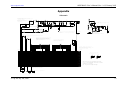
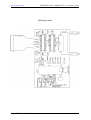
Connections common to both Mode 1 and 2 are;
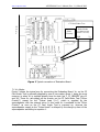
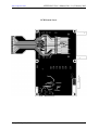
(a) Connect external wires (thick and short) from “CON_CAPXX” to the
“Pulsed loads” on the CF Card Under Test.
(b) Place jumpers on pins 3 and 4 of “J_VCC13_IN” and “J_VCC38_IN”.
Remember to use the series diode (remove “J_5V”) if using the 5V rail.
(c) Place jumpers
“J_ENABLE”,.
on
“J_RED&YLW”,
“J_GREEN”,
“J_PGOOD”
and
(d) Remove jumpers on “J_VS1”, “J_VS2”.
Mode 1 is accomplished by the following;
(a) Connect jumpers on “J_VCC13” and “J_VCC38”.
(b) Remove jumpers across pins 1-2 of both “JVCC_13_OUT” and
“JVCC_38_OUT”. Make sure that VCC on the CF card under test is not
connected to the Pulsed Load V+. Otherwise VCC will be short circuited by
the supercapacitor when it is discharged and the current limit circuit is not
in this path.
Mode 2 is when the supercapacitor supplies both the VCC for the PC Card Under Test
(“Other Circuitry”) as well as the “Pulsed loads”. In this mode all supplies are
delayed according to equation 1. Any voltage ripple on the supercapacitor due to
large currents will appear on the VCC rail.
Mode 2 is accomplished by the following;
(a) Remove the jumpers on “J_VCC13” and “J_VCC38”.
(b) Either ensure that VCC on the CF card under test is connected to the
Pulsed Load V+ and supply the load via thick wires as per Figure 2 or
place jumpers across pins 1-2 of both “JVCC_13_OUT” and
“JVCC_38_OUT”.
There are many other modes available. The Evaluation board is designed for
flexibility by allowing each section to be isolated or connected to external circuits.
NOTE: Care must be taken, in which ever mode is chosen, so that the charge up
time of the supercapacitor does not affect the operation of any reset or power rail
monitoring circuitry etc. As described in section 4.0 and 5.0, the “J_ENABLE” and
“H_PGOOD” signals may need to be interfaced with the CF Card Under Test for
proper control.
7.2 Current Measurement
Currents can be measured with a current probe or a voltage across a sense resistor.
A jumper can be replaced by an external wire loop which the current probe can
clamp on. If a current probe is not available then a sense resistor can be used in
© cap-XX Pty Ltd, 2003
10