1
RTC (Real-Time Clock)
A real-time clock is used to keep the real time and date, generate interrupt and provide timer and alarm functions. Due to a battery cell,
the operation of the real-time clock is enabled even when the microcontroller’s power supply goes off. The real-time clock is linked to
a development system via a 2x5 female connector provided on the RTC board and a 2x5 male connector provided on the I/O port of
the development system. The real-time clock communicates with the microcontroller using I2C serial communication.
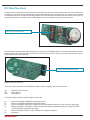
DIP switch SW1 is used to select a development
system to connect the RTC board to
Figure 1: RTC board
DIP switch SW1 is used to select a development system to connect the RTC additional board to. This switch also enables connection
between the SDA, SCL and INT-RTC pins provided on the RTC board and a serial I2C module built into the microcontroller. Figure 3
shows the pinout of the DIP switch SW1.
2x5 female connector enables the additional board
to be connected to a development system
Figure 2: RTC board’s bottom view
The function of pins provided on the PCF8583P circuit that is used for connection with the microcontroller:
INT
SCL
SDA
- Open drain interrupt output
- Serial clock line
- Serial data line
The function of pins provided on the 2x5 female connector CN1:
P0 P1
P2
P3
P4
P5
- SCL pin for EasyAVR and BIGAVR development systems;
- SDA pin for EasyAVR and BIGAVR development systems;
- SCL pin for BIGdsPIC, dsPICPRO, LV32MX and LV24-33 development systems; It is also used as an interrupt pin;
- SDA pin for BIGdsPIC, dsPICPRO, LV32MX and LV24-33 development systems and SCL pin for EasyPIC, BIGPIC, LV18FJ and EasyLV18 development systems;
- SDA pin for EasyPIC, BIGPIC, LV18FJ and EasyLV18 development systems;
- Interrupt pin;
MikroElektronika