1
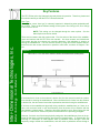
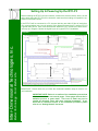
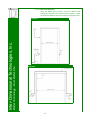
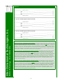
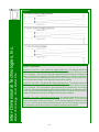
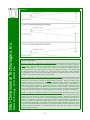
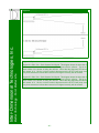
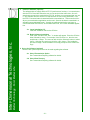
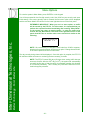
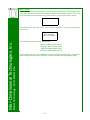
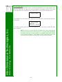
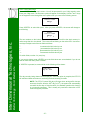
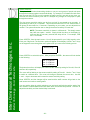
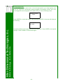
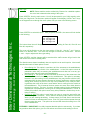
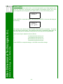
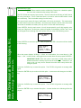
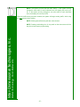
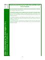
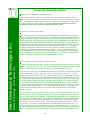
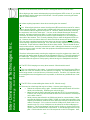
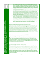
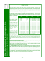
Diagram 5 Explanation:
Better Technology...For A Better Life
Inter-Dimensional Technologies, Inc.
Diagram 5
Diagram 5.a: Top View – Ideal Alignment (Recommended): This diagram shows the top view of a door sensor that
has ideal alignment in the horizontal plane. This is because the reflector is being hit by both beams. Notice that
neither of the alignment LED’s are lit. In terms of the horizontal alignment, this is the ideal alignment. How do you
know that you have an ideal alignment situation? By moving the reflector around and observing when the alignment LED’s turn off and on. This will help find the “sweet spot” (the center of the beams). If you find the center of
the beams (both horizontally and vertically), the door sensor will not lose alignment easily if a pedestrian bumps
the door sensor or reflector. There will be a certain amount of forgiveness.
Diagram 5.b: Top View – Borderline Alignment (Not Recommended): This diagram shows the top view of a door
sensor that does not have ideal alignment in the horizontal plane. Although the reflector i s being hit by both
beams, the beam depicted with the solid line is barely hitting the reflector. Notice that neither of the alignment
LED’s are lit. However, this is not an ideal alignment situation because, if the reflector is bumped by a pedestrian,
the sensor can lose alignment with the reflector easily. If this happens, a situation such as the one depicted in
Diagram 6.a can occur. In terms of horizontal alignment, this is not the ideal alignment situation. The reflector
and/or sensor should be adjusted. How do you know that you have a borderline alignment situation? By moving
the reflector around and observing when the alignment LED’s turn off and on. This will help find the “sweet
spot” (the center of the beams).
Diagram 5.c: Top View – Borderline Alignment (Not Recommended): This diagram shows the top view of a door
sensor that does not have ideal alignment in the horizontal plane. Although the reflector is being hit by both
beams, the beam depicted with the dashed line is barely hitting the reflector. Notice that neither of the alignment
LED’s are lit. However, this is not an ideal alignment situation because, if the reflector is bumped by a pedestrian,
the sensor can lose alignment with the reflector easily. If this happens, a situation such as the one depicted in
Diagram 6.b can occur. In terms of horizontal alignment, this is not the ideal alignment situation. The reflector
and/or sensor should be adjusted. How do you know that you have a borderline alignment situation? By moving
the reflector around and observing when the alignment LED’s turn off and on. This will help find the “sweet
spot” (the center of the beams) before mounting the reflector.
- 17 -