1
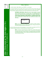
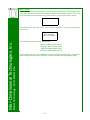
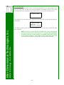
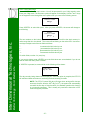
Communications standard dictates that the two devices cannot be
more than 50 feet apart.
1.b.i.
Connect the RTC-P3 to the PC (optional)
The RTC-P3 does not need to be connected to a PC in order to operate. The only time that the RTC-P3 and the PC interact is when
the traffic data is being transmitted. Therefore, if a PC is not available at the establishment, a laptop can be connected to the RTC-P3
periodically and the traffic data transmitted. In either case, the following should be done when connecting the RTC-P3 to the PC.
1.b.ii.
Connect the RTC-P3 to the Door Sensor(s)
In Step 1.a, the communications cable was installed. Now, it’s time
to connect the ends of the cable. Connect one end of the cable to
one of the three door sensor ports, labeled “Door 1,” “Door 2” and
“Door 3.” It does not matter into which port the cable is plugged.
However, it is usually only natural to start at Door 1. This will also
make it more logical when analyzing the data with the software.
For now, leave the other end of the cable unconnected. That will be
done when the door sensors are installed. If there is more than one
door sensor, connect the other cables to the RTC-P3 in the same
fashion.
Better Technology...For A Better Life
Inter-Dimensional Technologies, Inc.
Find the Serial cable that was included with the RTC-P3. It is the
cable with the nine-pin connectors. Connect the cable into the port
on the RTC-P3 labeled, “RS-232.” Connect the other end of the cable into a Serial port on the PC. If the PC does not have an available Serial port, the RTC-P3 can be connected to a USB port with a
Serial-to-USB converter that we resell.
1.b.iii. Connect the RTC-P3 to the Wall Outlet
Plug the two-prong connector on the power supply into the wall.
Plug the other end of the cable into the RTC-P3’s “Power” socket.
Do not turn on the traffic counter yet. We will turn it on after we have
the door sensors mounted.
-9-