1
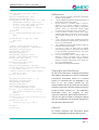
Application Note 1 – v1.0.5 – July 2014 FLIM measurements using SPC2 repeated for the desired number of shifts (gate width is never changed). When no more shifts are needed, the camera is closed. Now on the HDD are saved a series of files in SPC2 format acquired with the corresponding gate shift. These snaps can then be analysed in order to extract the desired information: i.e. for each pixel reconstruct the full decay histogram and then calculate the decay time constant. Since every snap can be composed by n>1 frames (in our example 10) it is recommended to average or sum all of them in one single frame. This can be done easily for example with ImageJ. A fast, powerful yet convenient way of analysing the MPD camera data is through the use of the PixBleach [9] plugin for ImageJ which allows to obtain a lifetime image once Snaps from SPC2 has been imported in ImageJ using the provided plugin. An accurate reading of ImageJ and PixBleach documentation is also recommended. The remaining parameter to take into account is that the SPC2 gate has a maximum shift range of 20 ns. This means that the SPC2 is equivalent to a TCSPC acquisition system with a 20 ns full scale range. Longer ranges might be achieved with a different technique that will be discussed in a future application note. Finally it worth noting that the SPC2 has already been used successfully to measure eGFP lifetimes of about 2 ns and that a peer reviewed paper has already been submitted. Gate calibration The actual width and phase of the gate signal obtained for a given set of parameters used with the SPC2_Set_Gate_Values function may vary among different SPC2 units, due to fabrication tolerances of the FPGA. While the gate width is calibrated by MPD before shipping the camera, the gate shift is not. This is done on purpose. In fact, the final shift of the gate signal with respect to the laser pulse is not only related to the shift internal to the camera, but also (and probably largely) to the delays introduced by cables and the laser itself. A calibration of the actual gate shift with respect to the laser excitation is therefore necessary after the camera is mounted into the measurement setup. This can be easily done by directly shining the laser onto the array, without interposing any fluorescent sample or filter, and performing a full measurement over the entire 20 ns shift range. By inspecting the measurement and finding the laser peak, it is possible to evaluate the shift between the actual laser pulse and the Int_Clk signal. Once this shift is known, it is advisable to adjust the length of the cable from the SYNC_OUT SMA output of the camera to the TRIG_IN of the laser in order to “centre” the fluorescence in the 20 ns FLIM window. This would avoid any folding of the fluorescence signal, avoiding at the same time the initial and final part of the FLIM window that presents poorer linearity. The calibration is also useful to zero any skew among pixels. In fact the gate applied to each pixel of the camera has a small skew compared to any other pixel. These relative skews are small and totally negligible in case of a FLIM acquisition, where the relevant information is constituted by decay times; anyway they might not be negligible in other cases like 3D indirect time of flight measurements in which the absolute delay IS the measure itself. The evaluation of actual gate width after calibration is possible by comparing photon counts obtained with and without the gating function, when the camera is illuminated with a constant light source. In this way it is also possible to check the gate width constancy against different gate shift values. An example code for this aim is the following: //SPC2 constructor and parameter setting out=(int)SPC2_Constr(&spc2,1,32,1,32, Advanced,""); AN1 -‐ 6