1
CLEAR-COM ECLIPSE
I-SERIES INTERCOM PANELS
INSTRUCTION MANUAL
i-Series Intercom Panels Instruction Manual
© 2007, 2009 Vitec Group Communications Ltd. All Rights Reserved.
Part Number 810305Z Rev. 4
Vitec Group Communications LLC
850 Marina Village Parkway
Alameda, CA 94501
U.S.A
Vitec Group Communications Ltd
7400 Beach Drive
IQ Cambridge
Cambridgeshire
United Kingdom
CB25 9TP
The Vitec Group plc
Beijing Representative Office
Room 706, Tower B
Derun Building, YongAn Dongli A No.3
Jianwai Ave., Chaoyang District
Beijing, P.R.China 100022
® Clear-Com, CellCom/FreeSpeak and the Clear-Com Communications Systems logo are registered
trademarks of The Vitec Group plc.
Website: www.clearcom.com
CONTENTS
OPERATING AN I-SERIES INTERCOM PANEL . . 1-1
Features of i-Series Intercom Panels . . . . . . . . . . . . . . . . . . . . . . . . 1-1
i-Series Construction . . . . . . . . . . . . . . . . . . . . . . . . . . . . . . . . . . . . 1-2
i-Series Module Descriptions . . . . . . . . . . . . . . . . . . . . . . . . . . . . . . 1-2
Key Module . . . . . . . . . . . . . . . . . . . . . . . . . . . . . . . . . . . . . . . . . . 1-2
Function Key Module . . . . . . . . . . . . . . . . . . . . . . . . . . . . . . . . . . 1-4
Mic-Headset Module . . . . . . . . . . . . . . . . . . . . . . . . . . . . . . . . . . . 1-5
Level-Control Module . . . . . . . . . . . . . . . . . . . . . . . . . . . . . . . . . . 1-5
AUX-101 Auxiliary Options Module. . . . . . . . . . . . . . . . . . . . . . . . 1-5
Standard i-Series panel Configurations. . . . . . . . . . . . . . . . . . . . . 1-8
Start-Up Sequences . . . . . . . . . . . . . . . . . . . . . . . . . . . . . . . . . . . . . 1-9
Non-Display Key Module Start-Up Sequence . . . . . . . . . . . . . . . . 1-9
Display Key Module Start-Up Sequence . . . . . . . . . . . . . . . . . . . . 1-9
Function Key Module Start-Up Sequence . . . . . . . . . . . . . . . . . . 1-10
Front Panel Controls and Lights . . . . . . . . . . . . . . . . . . . . . . . . . . . 1-10
A Note About Terminology . . . . . . . . . . . . . . . . . . . . . . . . . . . . . 1-10
About Displays . . . . . . . . . . . . . . . . . . . . . . . . . . . . . . . . . . . . . . 1-10
About Keys . . . . . . . . . . . . . . . . . . . . . . . . . . . . . . . . . . . . . . . . . 1-11
Temporary or Latched Action . . . . . . . . . . . . . . . . . . . . . . . . . 1-11
Active and Non-Active Keys . . . . . . . . . . . . . . . . . . . . . . . . . . 1-11
About Lights . . . . . . . . . . . . . . . . . . . . . . . . . . . . . . . . . . . . . . . . 1-12
Call-Waiting Light. . . . . . . . . . . . . . . . . . . . . . . . . . . . . . . . . . . 1-12
In-Use Light . . . . . . . . . . . . . . . . . . . . . . . . . . . . . . . . . . . . . . . 1-13
Telephone Off-Hook Light . . . . . . . . . . . . . . . . . . . . . . . . . . . . 1-13
Radio-Receiver Active Light . . . . . . . . . . . . . . . . . . . . . . . . . . 1-13
Panel Connected Light . . . . . . . . . . . . . . . . . . . . . . . . . . . . . . 1-14
Audio-Presence Light . . . . . . . . . . . . . . . . . . . . . . . . . . . . . . . 1-14
Incompatible Firmware Light . . . . . . . . . . . . . . . . . . . . . . . . . . 1-14
Summary of Key Module Lights . . . . . . . . . . . . . . . . . . . . . . . . . 1-14
Answer-Back Feature . . . . . . . . . . . . . . . . . . . . . . . . . . . . . . . . . 1-15
Answer-Back and Clear Keys . . . . . . . . . . . . . . . . . . . . . . . . . 1-15
Answering a Call with the Answer-Back Key . . . . . . . . . . . . . . 1-16
Answering a Second Call from the Answer-Back Stack . . . . . 1-17
Summary of Answer-Back and Clear Key Lights . . . . . . . . . . . . 1-18
Volume Controls . . . . . . . . . . . . . . . . . . . . . . . . . . . . . . . . . . . . . 1-18
Speaker and Headset Volume Controls . . . . . . . . . . . . . . . . . 1-18
Adjusting Listen Levels . . . . . . . . . . . . . . . . . . . . . . . . . . . . . . 1-19
Clear-Com Communication Systems
I-Series Instruction Manual
i
Resetting Listen Levels to the Default Level . . . . . . . . . . . . . . 1-21
Panel Upgrade Facility (Eclipse V5.1 or later) . . . . . . . . . . . . . 1-22
ACCESSING I-SERIES BASIC FUNCTIONS . . . . . 2-1
Turning the Gooseneck Microphone On and Off. . . . . . . . . . . . . . 2-1
Turning the Headset Microphone On and Off . . . . . . . . . . . . . . . . 2-2
Turning the Speaker On and Off . . . . . . . . . . . . . . . . . . . . . . . . . . 2-2
Using the “Listen” Key to Access Functions . . . . . . . . . . . . . . . . . 2-2
Activating the “Monitor Mode” of a Talk-with-Listen Key . . . . . . 2-3
Sending Call Signals . . . . . . . . . . . . . . . . . . . . . . . . . . . . . . . . . 2-4
Releasing Remote Telephone Lines . . . . . . . . . . . . . . . . . . . . . 2-5
Summary of Function Key Module Lights . . . . . . . . . . . . . . . . . . . 2-7
ACCESSING I-SERIES ADVANCED FUNCTIONS 3-1
Overview of Advanced Features . . . . . . . . . . . . . . . . . . . . . . . . . . 3-2
Telephone Dialing from the Keypad (#1 Key) . . . . . . . . . . . . . . . . 3-2
Accessing Local Exclusive (#2 Key) . . . . . . . . . . . . . . . . . . . . . . . 3-3
Local Page Override (#3 Key). . . . . . . . . . . . . . . . . . . . . . . . . . . . 3-4
IFB, Party Line and Fixed Group Assignments (#4 key) . . . . . . . . 3-4
Setting Up IFB Sources and Destinations on an i-Series panel 3-5
Setting Up Party Line members on an i-Series panel . . . . . . . . 3-5
Setting Up Fixed Group members on an i-Series panel . . . . . . 3-6
Local Key Assignment (#5 Key) . . . . . . . . . . . . . . . . . . . . . . . . . . 3-6
Swap Page (#6 Key) . . . . . . . . . . . . . . . . . . . . . . . . . . . . . . . . . . 3-10
Local Preferences (#7 Key). . . . . . . . . . . . . . . . . . . . . . . . . . . . . 3-10
Listen Level Reset . . . . . . . . . . . . . . . . . . . . . . . . . . . . . . . . . . 3-11
Gooseneck Microphone Volume Level . . . . . . . . . . . . . . . . . . 3-11
Headset Microphone Volume Level. . . . . . . . . . . . . . . . . . . . . 3-12
Sidetone Volume Level . . . . . . . . . . . . . . . . . . . . . . . . . . . . . . 3-12
Exit. . . . . . . . . . . . . . . . . . . . . . . . . . . . . . . . . . . . . . . . . . . . . . 3-13
Accessing Port Information (#9 Key). . . . . . . . . . . . . . . . . . . . . . 3-13
Clearing the Current Programming . . . . . . . . . . . . . . . . . . . . . . . 3-13
Escaping the Current Programming . . . . . . . . . . . . . . . . . . . . . . 3-13
Entering the Current Programming . . . . . . . . . . . . . . . . . . . . . . . 3-14
Adjusting Background Lighting . . . . . . . . . . . . . . . . . . . . . . . . . . 3-14
Selecting a Feature from the Feature Menu . . . . . . . . . . . . . . . . 3-15
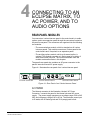
CONNECTING TO AN ECLIPSE MATRIX, TO AC
POWER, AND TO AUDIO OPTIONS . . . . . . . . . . . 4-1
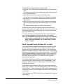
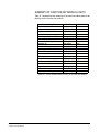
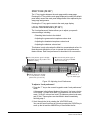
Rear-Panel Modules . . . . . . . . . . . . . . . . . . . . . . . . . . . . . . . . . . . . . 4-1
AC Power . . . . . . . . . . . . . . . . . . . . . . . . . . . . . . . . . . . . . . . . . . . 4-1
ii
Clear-Com Communication Systems
I-Series Instruction Manual
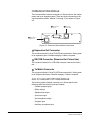
Communications Module. . . . . . . . . . . . . . . . . . . . . . . . . . . . . . . . 4-2
Expansion Out Connector. . . . . . . . . . . . . . . . . . . . . . . . . . . . . 4-2
DB-15M Connector (Reserved for Future Use) . . . . . . . . . . . . 4-2
To Matrix Connector . . . . . . . . . . . . . . . . . . . . . . . . . . . . . . . . . 4-2
AUX-101 Auxiliary Options Module. . . . . . . . . . . . . . . . . . . . . . . . 4-2
General Purpose Inputs Connector . . . . . . . . . . . . . . . . . . . . . 4-3
Relay Outputs Connector . . . . . . . . . . . . . . . . . . . . . . . . . . . . . 4-9
External Speaker Input Connector . . . . . . . . . . . . . . . . . . . . . 4-10
Line-Level Output Connector . . . . . . . . . . . . . . . . . . . . . . . . . 4-10
Hot-Microphone Output Connector. . . . . . . . . . . . . . . . . . . . . 4-11
Balanced Program Input Connector . . . . . . . . . . . . . . . . . . . . 4-11
External Dynamic Microphone Input Connector . . . . . . . . . . . 4-11
Connecting to an i-Series Expansion Panel . . . . . . . . . . . . . . . . . . 4-12
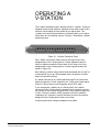
OPERATING A V-STATION . . . . . . . . . . . . . . . . . . 5-1
Allowable Configurations . . . . . . . . . . . . . . . . . . . . . . . . . . . . . . . . . 5-3
A Fully Populated Configuration . . . . . . . . . . . . . . . . . . . . . . . . . . . . 5-3
INSTALLING AN I-SERIES INTERCOM PANEL. . . 6-1
Equipment Placement. . . . . . . . . . . . . . . . . . . . . . . . . . . . . . . . . . . . 6-1
Mains AC Power . . . . . . . . . . . . . . . . . . . . . . . . . . . . . . . . . . . . . . . . 6-1
Adjustments . . . . . . . . . . . . . . . . . . . . . . . . . . . . . . . . . . . . . . . . . . . 6-1
Configuration . . . . . . . . . . . . . . . . . . . . . . . . . . . . . . . . . . . . . . . . . . 6-1
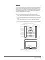
Wiring . . . . . . . . . . . . . . . . . . . . . . . . . . . . . . . . . . . . . . . . . . . . . . . . 6-2
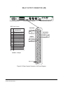
Pinout Diagrams . . . . . . . . . . . . . . . . . . . . . . . . . . . . . . . . . . . . . . . . 6-3
Expansion Out Connector (J1) . . . . . . . . . . . . . . . . . . . . . . . . . . . 6-4
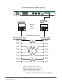
RJ-45 to Matrix Connector (J3) . . . . . . . . . . . . . . . . . . . . . . . . . . . 6-5
General Purpose Inputs Connector (J5A) . . . . . . . . . . . . . . . . . . . 6-6
Relay Output Connector (J5B) . . . . . . . . . . . . . . . . . . . . . . . . . . . 6-7
Speaker-Feed Output (J6). . . . . . . . . . . . . . . . . . . . . . . . . . . . . . . 6-8
Line-Level Output (J7). . . . . . . . . . . . . . . . . . . . . . . . . . . . . . . . . . 6-8
Hot Microphone Output (J8) . . . . . . . . . . . . . . . . . . . . . . . . . . . . . 6-9
Program Input (J9) . . . . . . . . . . . . . . . . . . . . . . . . . . . . . . . . . . . . 6-9
Auxiliary Microphone Input (J10). . . . . . . . . . . . . . . . . . . . . . . . . . 6-9
MAINTAINING AN I-SERIES INTERCOM PANEL . 7-1
General Troubleshooting . . . . . . . . . . . . . . . . . . . . . . . . . . . . . . . . . 7-1
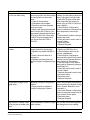
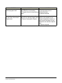
Troubleshooting Tips. . . . . . . . . . . . . . . . . . . . . . . . . . . . . . . . . . . . . 7-1
Analog Block Diagram. . . . . . . . . . . . . . . . . . . . . . . . . . . . . . . . . . 7-5
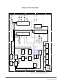
Panel Block Diagram. . . . . . . . . . . . . . . . . . . . . . . . . . . . . . . . . . . 7-6
Clear-Com Communication Systems
I-Series Instruction Manual
iii
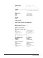
SPECIFICATIONS . . . . . . . . . . . . . . . . . . . . . . . . . . 8-1
GLOSSARY . . . . . . . . . . . . . . . . . . . . . . . . . . . . . . . 9-1
Eclipse Manuals . . . . . . . . . . . . . . . . . . . . . . . . . . . . . . . . . . . . . . . . 9-5
Software Manuals . . . . . . . . . . . . . . . . . . . . . . . . . . . . . . . . . . . . . 9-5
Hardware Manuals . . . . . . . . . . . . . . . . . . . . . . . . . . . . . . . . . . . . 9-5
LIMITED WARRANTY . . . . . . . . . . . . . . . . . . . . . . . W-I
TECHNICAL SUPPORT & REPAIR POLICY. . . . . W-V
TECHNICAL SUPPORT POLICY . . . . . . . . . . . . . . . . . . . . . . . . . . W-v
RETURN MATERIAL AUTHORIZATION POLICY . . . . . . . . . . . . . W-vi
REPAIR POLICY . . . . . . . . . . . . . . . . . . . . . . . . . . . . . . . . . . . . . W-viii
iv
Clear-Com Communication Systems
I-Series Instruction Manual
FIGURES
Figure 1-1 Key Modules................................................................... 1-3
Figure 1-2 Function Key Modules.................................................... 1-4
Figure 1-3 Mic-Headset Module ...................................................... 1-5
Figure 1-4 Level-Control Module ..................................................... 1-5
Figure 1-5 The Eleven Front-Panel Modules................................... 1-7
Figure 1-6 Standard Panels 1.......................................................... 1-8
Figure 1-7 Standard Panels 2.......................................................... 1-9
Figure 1-8 Key Module .................................................................. 1-10
Figure 1-9 Answer-Back and Clear Keys....................................... 1-16
Figure 1-10 Answering a Call from an Unassigned Source at the Answer-Back Key............................................................................... 1-17
Figure 1-11 Main Volume and Program Volume Controls ............. 1-18
Figure 1-12 Adjusting Listen Levels Method 1............................... 1-20
Figure 1-13 Adjusting Listen Levels Method 2............................... 1-21
Figure 2-1 Basic Function Keys....................................................... 2-1
Figure 2-2 Accessing Features from the Listen Key........................ 2-3
Figure 2-3 Activating the “Monitor Mode” of a Talk-with-Listen Key 2-4
Figure 3-1 Features Accessed by Keys on the Numeric Keypad .... 3-1
Figure 3-2 Telephone Dialing from the Function Keypad Module ... 3-3
Figure 3-3 Assigning a Remote Destination to a Talk or Talk-with-Listen
Key................................................................................................... 3-7
Figure 3-4 Assigning a Remote Source to a Listen Key .................. 3-8
Figure 3-5 Adjusting Local Preferences......................................... 3-10
Figure 3-6 Submenu of Display Contrast Values........................... 3-14
Figure 3-7 Submenu of Baud Rate Values .................................... 3-15
Figure 3-8 Selecting a Feature from the Feature Menu................. 3-16
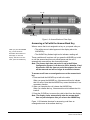
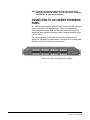
Figure 4-1 Rear Panel of an i-Series Intercom Panel ...................... 4-1
Figure 4-2 Communications Module Connectors ............................ 4-2
Figure 4-3 Auxiliary Options Module Connectors ............................ 4-3
Figure 4-4 i-Series panel Expansion Panel ................................... 4-12
Figure 5-1 v-Station Expansion Panel ............................................. 5-1
Figure 5-2 Two v-stations control and display listen levels for one i-Series panel ......................................................................................... 5-2
Figure 5-3 Connecting two v-stations to an i-Series panel .............. 5-2
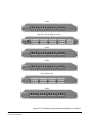
Figure 5-4 A fully populated configuration of v-stations................... 5-4
Figure 5-5 Connecting a fully populated configuration of v-stations 5-5
Figure 6-1 Matrix Frame to Panel Wiring...................................... 6-2
Figure 6-2 Expansion Out Connector Pinout Diagram .................... 6-4
Figure 6-3 RJ-45 to Matrix Connector Pinout Diagram.................... 6-5
Figure 6-4 General Purpose Inputs Connector Pinout Diagram ...... 6-6
Figure 6-5 Relay Outputs Connector (J3) Pinout Diagram .............. 6-7
Figure 6-6 Connector Pinout Diagrams for Speaker-Feed Output and
Line-Level Output ............................................................................ 6-8
Figure 6-7 Connector Pinout Diagrams for Hot Microphone Output (J8),
Program Input (J9), and Auxiliary Microphone Input (J10) .............. 6-9
Figure 7-1 Reset the panel if problems occur.................................. 7-1
Clear-Com Communication Systems
I-Series Instruction Manual
i
Figure 7-1 Analog Block Diagram.................................................... 7-5
Figure 7-2 Panel Block Diagram...................................................... 7-6
ii
Clear-Com Communication Systems
I-Series Instruction Manual
IMPORTANT SAFETY
INSTRUCTIONS
For your safety, it is important to read and follow these
instructions before operating an i-series panel:
(1) WARNING: To reduce the risk of fire or electric shock, do not
expose an i-Series panel to rain or moisture. Do not operate an
i-Series panel near water, or place objects containing liquid on it. Do
not expose an i-Series panel to splashing or dripping water.
Please read and follow
these instructions
before operating an
i-Series panel.
(2) For proper ventilation, make sure ventilation openings are not
blocked. Install the i-Series panel according to the directions in the
Installation Chapter of this manual.
(3) Do not install an i-Series panel near a heat source such as a
radiator, heat register, stove, or other apparatus (including amplifiers)
that produces heat. Do not place naked flame sources such as candles
on or near an i-Series panel.
(4) Do not defeat the safety purpose of the polarized or grounding-type
plug. A polarized plug has two blades, with one blade wider than the
other. A grounding-type plug has two blades and a third grounding
prong. The wide blade or the third prong is provided for your safety. If
the provided plug does not fit into your outlet, consult an electrician for
replacement of the obsolete outlet.
(5) Protect the power plug from being walked on or pinched particularly
at plugs, convenience receptacles, and the point where they exit from
the i-Series panel’s chassis.
(6) Only use attachments/accessories specified by Clear-Com
Intercom Systems.
(7) Unplug the i-Series panel during lightning storms or when unused
for long periods of time.
(8) Refer all servicing to qualified service personnel. Servicing is
required when:
• The i-Series panel has been damaged in any way, such as when
a power-supply cord or plug is damaged.
• Liquid has been spilled or objects have fallen into the i-Series
panel’s chassis.
• The i-Series panel has been exposed to rain or moisture.
• The i-Series panel does not operate normally.
• The i-Series panel has been dropped.
Please familiarize yourself with the safety symbols in Figure 1. When
you see these symbols on an i-Series panel, they warn you of the
potential danger of electric shock if the i-Series panel is used
Clear-Com Communication Systems
I-Series Instruction Manual
iii
improperly. They also refer you to important operating and
maintenance instructions in the manual.
CAUTION
RISK OF ELECTRIC SHOCK
DO NOT OPEN
This symbol alerts you to the presence of uninsulated dangerous
voltage within the product's enclosure that might be of sufficient
magnitude to constitute a risk of electric shock. Do not open
the product's case.
This symbol informs you that important operating and maintenance instructions are included in the literature accompanying
this product.
Figure 1: Safety Symbols
iv
Clear-Com Communication Systems
I-Series Instruction Manual
1
Clear-Com i-series intercom
panels are designed with
configurable front and back
panels.
OPERATING AN
I-SERIES INTERCOM
PANEL
The i-series of intercom panels for the Eclipse matrix system represent
an innovative concept in intercom panel design. Each panel is
constructed from several individual units called modules, which can be
added or removed in the field, giving you exceptional flexibility in
planning a panel’s initial configuration and then easily changing the
configuration as future operational needs change.
FEATURES OF I-SERIES INTERCOM
PANELS
The i-series design emphasizes simplicity. No specialized training is
required to operate an i-series panel. Intuitive lighting indicates the
status of keys for ease of use. Each key may be programmed as either
a talk, a listen, or a talk-with-listen.
Features of the i-Series panels include:
• Available in a number of standard configurations with 8, 16 or 32
keys.
• Up to five expansion panels can be connected to an i-Series
panel (E-1410E expansion panels) as described in chapter 5 of
this manual.
• Full graphic LED-backlit displays for each key on display panels.
• 16-button keypad module for DTMF dialing and panel
reprogramming (I-1430E and I-1470E only).
• Individual listen level adjust on every panel.
• Auto-sensing headset and microphone connectors.
• Access to multiple audio sources and multiple speaker and
headset inputs and outputs when an auxiliary options module is
installed (I-1470E only). The auxiliary options module also
provides you with two relays and two GPIs (general-purpose
inputs) that can be used either locally or system-wide.
• Advanced menu features allow you to assign new destinations
and sources to your panel directly from your panel, to program
IFB sources and destinations, to dial telephone interfaces, to
transform your panel into an assignment panel, to reset local
volume levels, and more.
Clear-Com Communication Systems
I-Series Instruction Manual
1-1
I-SERIES CONSTRUCTION
i-Series panels are sturdily constructed from the highest quality
components. Each i-Series panel’s chassis is constructed of
cold-rolled steel. Front-panel modules and removable rack ears are
cast from aluminum. All external connectors and switches are made of
the highest quality components and are structurally reinforced.
Keys feature long-life LED illumination. Displays are full-graphic LCD
with long-life LED backlighting.
i-Series internal architecture is based on the widely used Motorola
M-Core processor. All audio is digitized by CODECs and routed to a
DSP to be controlled as desired by the user.
All i-series panels have internal power supplies.
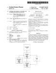
I-SERIES MODULE DESCRIPTIONS
i-Series intercom panels are designed in standardized units called
modules. Because the panels are designed this way, you can add or
remove components, such as keys, in the field without replacing the
entire intercom panel. Repairing panels is easier, faster, and less
expensive. The following sections give you an overview of i-series
modules.
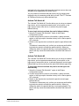
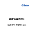
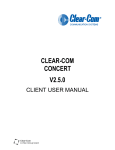
KEY MODULE
The key module is the basic building block of an i-series intercom
panel. A panel can accommodate from one to four key modules which
can be added or removed as needed.
Each key module has eight backlit keys that glow in either green or red
to indicate their talk/listen status. Each key has a 5-character
alphanumeric display that shows its currently programmed
assignment. The alphanumeric name of an assignment is typically
called a “label.”
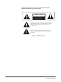
Display panels feature backlit LCD displays with labels that are
updated as you program them from the Eclipse Configuration System.
Non-display panels have slots for paper labels. A display and
non-display key module are illustrated in Figure 1-1.
1-2
Clear-Com Communication Systems
I-Series Instruction Manual
Display Key Module
with Electronic Labels
+Cams Phone IFB-1 IFB-2
IFB-3 PGM
+Cams Dir
Non-Display Key Module
with Printed Labels
+Cams
Phone IFB-1 IFB-2
+Cams
Dir
IFB-3 Pgm
Figure 1-1: Key Modules
Clear-Com Communication Systems
I-Series Instruction Manual
1-3
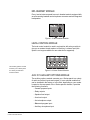
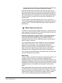
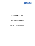
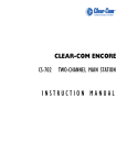
FUNCTION KEY MODULE
The function key module contains the intercom panel’s basic and
advanced controls. There are two types of function key modules in the
i-series. The 16-key module has a numeric keypad while the 4-key
module does not, as illustrated in Figure 1-2.
The 4-key module contains the keys that control basic intercom
functions such as switching between gooseneck/headset speakers
and microphones, sending call signals, and adjusting listen levels. It
has separate volume controls for intercom and program sources. The
operation of this module is discussed later in the chapter.
The 16-key module includes the basic function keys and adds a
12-button numeric keypad for dialing telephone interfaces and for
programming advanced features. Advanced features allow you to:
• Temporarily deactivate all latched keys on a panel.
• Override the on/off or volume settings at a destination.
• Assign new sources and destinations to your panel from your
panel.
• Program IFB sources and destinations.
• Reset microphone and sidetone volume levels.
• Receive a variety of information about your panel on the panel’s
LCD displays.
These functions are described in detail later in this chapter.
Function Key Module without Keypad
Function Key Module with Keypad
MAIN
MAIN
2
ABC
3
5
JKL
6 MNO
7 PQRS
8
TUV
9 WXYZ
RED
0
CLR
#
GN MIC
GN MIC
1
HS MIC
HS MIC
4
SPKR ON
LISTEN
VOL / PROG
SPKR ON
LISTEN
*
GHI
DEF
VOL / PROG
GRN
Figure 1-2: Function Key Modules
1-4
Clear-Com Communication Systems
I-Series Instruction Manual
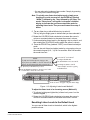
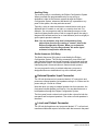
MIC-HEADSET MODULE
Every i-series intercom panel has a mic-headset module equipped with
an auto-sensing headset and microphone connector and an integrated
loudspeaker.
Figure 1-3: Mic-Headset Module
LEVEL-CONTROL MODULE
The level-control module is used in conjunction with a key module to
give you a constant visual read-out of each key’s volume level (this
option is no longer available for new sales but is supported).
The auxiliary options module
connects your i-Series panel
to a variety of audio and
control functions.
Figure 1-4: Level-Control Module
AUX-101 AUXILIARY OPTIONS MODULE
The auxiliary options module connects your i-Series panel to a variety
of audio and control inputs and outputs. It is an optional module that
can be installed in the factory or in the field, depending on your needs.
Located on the rear-panel of the i-Series panel’s chassis, it provides
the following functions:
• General purpose inputs
• Relay outputs
• Speaker-feed output
• Line-level output
• Hot-microphone output
• Balanced-program input
• Auxiliary microphone input
Clear-Com Communication Systems
I-Series Instruction Manual
1-5
The auxiliary option module’s functions are described in detail later in
this chapter.
1-6
Clear-Com Communication Systems
I-Series Instruction Manual
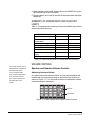
KEY MODULES
+Cams Phone IFB-1 IFB-2
IFB-3 PGM
+Cams Dir
+Cams
Phone IFB-1 IFB-2
+Cams
Dir
IFB-3 Pgm
Non-Display Key Module
(No longer sold)
Display Key Module
Blank Key Module
CLEAR
CLEAR
Phone IFB-1 IFB-2
Phone IFB-1 IFB-2
Dir IFB-3 PGM
Dir
IFB-3 Pgm
ANSWR
ANSWR
Non-Display Key Module
with Clear and Answer Keys
(No longer available)
Display Key Module
with Clear and Answer Keys
FUNCTION KEY MODULES
MA IN
GN MIC
1
HS MIC
4
SPKR ON
LISTEN
GHI
2
ABC
3
5
JKL
6 MNO
DEF
7 PQRS
8
TUV
9 WXYZ
RED
0
CLR
#
*
GRN
Function Key Module with Keypad
MAIN
GN MIC
HS MIC
VOL / PR
OG
SPKR ON
LISTEN
Function Key Module without Keypad
MIC-HEADSET MODULES
Mic-Headset Module
VOL / PR
OG
Blank Mic-Headset Module
Blank Function Key Module
LEVEL-CONTROL MODULE
Level-Control Module
(No longer available)
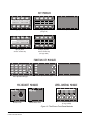
Figure 1-5: The Eleven Front-Panel Modules
Clear-Com Communication Systems
I-Series Instruction Manual
1-7
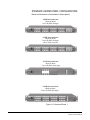
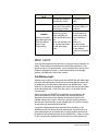
STANDARD I-SERIES PANEL CONFIGURATIONS
Below are illustrations of the standard i-Series panels.
i1430E Intercom Panel
4 Display Key Modules
Function Key Module with Keypad
i1470E Intercom Panel
4 Display Key Modules
Function Key Module with Keypad
AUX-101 module factory fitted
i1110E Intercom Panel
1 Display Key Module
Function Key Module without Keypad
i1410E Intercom Panel
4 Display Key Modules
Function Key Module without Keypad
Figure 1-6: Standard Panels 1
1-8
Clear-Com Communication Systems
I-Series Instruction Manual
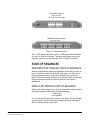
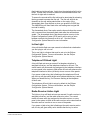
i1210E Intercom Panel
2 Display Key Modules
Function Key Module without Keypad
e1410E Key Expansion Panel
4 Display Key Modules
Figure 1-7: Standard Panels 2
The i-1470E panel is the same as the i-1430E panel with the addition
of a AUX-101 option card fitted. The other main panels (but not the
expansion panels) may also have the AUX-101 option card fitted.
START-UP SEQUENCES
NON-DISPLAY KEY MODULE START-UP SEQUENCE
When a panel with non-display key modules is connected to power, all
keys on each key module will flash red, then green, and will revert to
their programmed colors (red for talk or talk-with-listen; green for
listen). If there is no communication to the Eclipse matrix, the keys will
flash red once per second until communication to the matrix is
established.
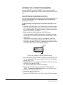
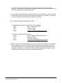
DISPLAY KEY MODULE START-UP SEQUENCE
When a panel with display key modules is connected to power, each of
the display modules will show the following message:
Clear-Com
Vx.x.x@2000
“V.x.x.x” represents the firmware version of the panel. All keys will flash
red, then green, and will show their programmed colors and labels if
there is communication to the matrix.
Clear-Com Communication Systems
I-Series Instruction Manual
1-9
If there is no communication to the matrix, the display will show the
message “No connection to Eclipse.” The keys will then flash red four
times per second until communication to the Eclipse matrix is
established.
FUNCTION KEY MODULE START-UP SEQUENCE
When an intercom panel is connected to power, all of the keys on the
function key module will flash red, then green, and will revert to their
programmed colors if there is communication to the matrix.
If there is no communication to the matrix, the keys will be dark until
communication is established.
FRONT PANEL CONTROLS AND LIGHTS
A NOTE ABOUT TERMINOLOGY
In this manual, the term “source” refers to a device—intercom panel,
interface, beltpack, or a variety of other devices—that sends audio to
your intercom panel. It represents a “listen” path to your panel. The
term “destination” refers to a device to which you send audio. It
represents a “talk” path from your intercom panel.
The names of these sources and destinations appear in the display of
your intercom panel and are called “labels.” A label is a 5-character
alphanumeric name that identifies a source, destination, or control
function accessed by your intercom panel.
ABOUT DISPLAYS
The 5-character name, or “label,” that you assign to a key is displayed
next to the key on the key module (Figure 1-8). The labels on the upper
row refer to their corresponding upper-row keys and the labels on the
lower row refer to their corresponding lower-row keys.
Keys
Alphanumeric Key
Names or "Labels"
+Cams Phone IFB-1 IFB-2
IFB-3 PGM
+Cams Dir
Figure 1-8: Key Module
1-10
Clear-Com Communication Systems
I-Series Instruction Manual
Display panels have full-graphic LED-backlit displays that you program
from the Eclipse Configuration System. Non-display panels have metal
grooves into which paper labels can be inserted. Paper labels can be
printed from the Eclipse Configuration System.
ABOUT KEYS
Each key on any key module can be assigned as a talk, a listen, or a
talk-with-listen from the Eclipse Configuration System. See the Eclipse
Configuration System Manual for more information.
Temporary or Latched Action
When you press a key to talk or listen, the key can be switched on
either temporarily or continuously.
When you switch a key on temporarily, it is active for the particular
period of time you require. Press and hold the key down for the desired
length of time needed to talk or listen, then release the key to return it
to its non-active state. You will only be able to talk or listen while you
press the key.
Continuous or “latched” action allows you to lock a key into place, so
that you can talk or listen hands-free. Quickly tap a key to “latch” or
“lock” it into place to talk or listen. The key will glow brightly to indicate
that it is active. The key will remain latched until you tap it again to
return it to its non-active state.
Active and Non-Active Keys
When you activate a key—that is, when you press or latch the key to
talk or listen— the key becomes bright red or green. When you press
or latch an assigned talk key, the key lights up bright red while you talk
to the destination. When you press or latch an assigned listen key, the
key lights up bright green while you listen to the source.
Active keys are bright red or
green. Non-active keys are
dim red or green. Keys that
are not assigned are off, with
no illumination.
Clear-Com Communication Systems
I-Series Instruction Manual
Otherwise, a key that is not active—that is, a key that is not being used
to talk or listen— will be dimmed: dim red for a talk or talk-with-listen
key; dim green for a listen key.
Table 1-1 shows the key colors associated with active or non-active
talk, listen, or talk-with-listen keys.
1-11
KEY
TALK
ACTIVE
NON-ACTIVE
A talk key glows bright
red when you press or
latch the key to talk.
LISTEN
A listen key glows bright
green when you press or
latch the key to listen.
TALK-WITH-LISTEN A talk-with-listen key
(combo key) glows
(COMBO)
bright red when you
Setting up a combo press or latch the key to
key is described in the talk.
When you activate a lisECS User Manual
ten, the talk-with-listen
under “Panel
key will glow bright
Programming”.
green.
A talk key glows dim
red when it is not
active.
A listen key glows
dim green when it is
not active.
If in talk mode, a
talk-with-listen key
(combo key) glows
dim red when not
active.
There is no
non-active listen
mode. A talk-with-listen key always
reverts to non-active
talk.
Table 1-1: Key Colors for Active and Non-Active Keys
ABOUT LIGHTS
A key can be programmed to light up in a variety of ways to indicate its
status. These options are discussed in the following sections. If you
decide to use one of these options, it must usually first be set up in the
Eclipse Configuration System. A table summarizing all of the light
options is located at the end of the section.
Call-Waiting Light
When a source calls an i-Series panel the ANSWR key will flash bright
red at the call waiting rate (four times per second) and the source will
be displayed in the call waiting stack above the ANSWR key. If any
other key on the panel is assigned to the source this key will also flash
at the call waiting rate. Audio from the source can be heard at the
i-Series panel.
When you press the ANSWR key (or another key assigned to the
source and flashing) to talk, the ANSWR key and any other key
assigned to the source stops flashing and becomes bright red to
indicate that the call is active. When you release the key pressed to
take the call it becomes dim red to indicate that it is not active as well
as any other key associated with the call.
If a call is being answered when a second source calls you, the
ANSWR key will not flash at the call-waiting rate, but will continue to
glow solidly bright red to indicate that it is active and the new call will
be added to the call waiting stack on the ANSWR key. If there is a key
on the i-Series panel assigned to the source of the new call this will
1-12
Clear-Com Communication Systems
I-Series Instruction Manual
flash bright red at the call rate. Audio from the stacked call will not be
heard. Further calls will also be added to the answerback stack until
the limit of eight calls is reached.
To answer the second call the first call must be terminated by releasing
the key pressed to answer the first call. The first call will then be
cleared from the call waiting stack either on the expiry of the
Answerback Auto Clear timeout or when you press the CLEAR key.
The ANSWR key will then flash at the call waiting rate to signal the
next call is waiting.
The Answerback Auto Clear option sets the timeout before the current
call is removed from the answer-back stack after the call has been
ended. The Answerback Auto Clear timeout option is set up in the
Eclipse Configuration System (ECS) and it can be set to a value
between one and sixty seconds or set to off. See the Eclipse
Configuration System Manual for more information.
In-Use Light
A key will double-flash once per second to indicate that a destination
you are trying to call is in use.
The in-use light is a feature that must be set up in the Eclipse
Configuration System. For more information, see the Eclipse
Configuration System Manual.
Telephone Off-Hook Light
A key will flash red once per second if a telephone interface is
assigned to that key, and the telephone interface is off-hook. The
central matrix will cause each key assigned to the telephone interface
on every panel in the system to flash at the off-hook rate whenever the
telephone interface is active (off-hook) at one or more of the panels.
If you press or latch a key that is flashing at the telephone off-hook
rate, the key will glow solidly bright red to indicate that the key is active.
When you release the key, it will resume flashing at the telephone
off-hook rate.
The telephone off-hook light is set up by default in the Eclipse
Configuration System. For more information, see the Eclipse
Configuration System Manual.
Radio-Receiver Active Light
The light on a key will flash red once per second if a radio receiver is
assigned to that key, and the radio receiver is active. The central
matrix will cause each key assigned to the radio receiver on every
panel in the system to flash at the radio-receiver active rate whenever
the radio receiver is active at one or more of the panels.
If you press or latch a key that is flashing at the radio-receiver active
rate, the key will glow solidly red to indicate that the key is active.
Clear-Com Communication Systems
I-Series Instruction Manual
1-13
When you release the key, it will resume flashing at the radio-receiver
active rate.
The radio-receiver active light requires that the radio receiver is
connected via a FOR-22 interface. The radio receiver active light
feature must be enabled in the Eclipse Configuration System under the
Advanced Settings and Tallies options for the FOR-22 interface. For
more information, see the Eclipse Configuration System Manual.
Panel Connected Light
When the Station Connected Tally option is selected in the Eclipse
Configuration System software (under Advanced Settings > Global
Settings), whenever a destination panel is connected to the Matrix
frame its assigned key on your panel will flash red once per second.
This option is primarily used when a destination panel is connected to
the Matrix frame via a long-line link that might be active only at certain
times.
The Station Connected Tally is a feature that must be set up in the
Eclipse Configuration System program. For more information, see the
Eclipse Configuration System Manual.
Audio-Presence Light
If you assign a source to your panel as a listen-only key, the key will
flash green once per second if there is audio present at the source.
The audio-presence light is a feature that must be set up in the Eclipse
Configuration System. For more information, see the Eclipse
Configuration System Manual.
Incompatible Firmware Light
If the firmware on your panel is incompatible with the matrix, all lights
on the panel will blink dim red once per second, and if displays are
present, they will read: “No connection to Eclipse”.
SUMMARY OF KEY MODULE LIGHTS
Table 1-2 summarizes the meaning of key colors and blink rates on a
key module.
1-14
Clear-Com Communication Systems
I-Series Instruction Manual
DISPLAY KEYS
LED COLOR
Key programmed as listen-only
Key programmed as talk or
talk-with-listen
Listen key active
Talk-with-listen key active
Talk-with-listen key listen-only
active
Call Waiting
In Use
Audio Presence
Panel Connected
Telephone Off-Hook
Radio Receiver Active
Incompatible Firmware
dim red
dim red
dim green
bright red
BLINK RATE
dim green
dim red
none
none
bright green
bright red
bright green
none
none
none
bright red
dim red
dim green
4x per second
2x per second
1x per second
(continued)
1x per second
1x per second
1x per second
1x per second
Table 1-2: Key Colors and Blink Rates
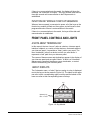
ANSWER-BACK FEATURE
With the answer-back
feature, you can reply to
incoming calls from sources
not assigned to keys on your
panel.
With the answer-back feature you can reply to incoming calls from
sources not assigned to keys on your intercom panel. You can also call
out to destinations not assigned to keys on your panel.
If a second unassigned source calls you while you are speaking to the
first unassigned source, the second call will be placed in the
“answer-back stack,” a group of up to eight waiting calls that are
answered in sequence.
Note: All incoming calls can be answered at the answer-back
key—whether from sources with assigned keys on the
intercom panel or from sources without assigned keys.
Typically, however, only calls from sources without
assigned keys are answered there.
The following sections describe how to use the answer-back feature.
Answer-Back and Clear Keys
You cannot latch an outgoing
call from the answer-back
key. This function is
momentary only.
Clear-Com Communication Systems
I-Series Instruction Manual
The answer-back key is the leftmost lower key on any intercom panel.
The clear key is the leftmost upper key on any intercom panel. (See
Figure 1-9). The keys are labeled “ANSWR” and “CLEAR.”
1-15
Clear Key
Clear Key
Answer-Back Key
Answer-Back Key
Figure 1-9: Answer-Back and Clear Keys
Answering a Call with the Answer-Back Key
When a source that is not assigned to a key on your panel calls you:
When you press the ANSWR
key, you will talk to the
destination whose label is in
the display. To clear the
display, and talk to the next
caller, press the CLEAR key.
• The calling source’s label appears in the display above the
ANSWR key.
• The ANSWR key flashes bright red to indicate a waiting call.
These conditions will continue until you press the ANSWR key to talk
or until the answer-back time-out period lapses and the call is
automatically removed from the answer-back stack.
Note: The answer-back time-out period is set in the Eclipse
Configuration System. It can be set to Off or between 10 and
60 seconds. After the time-out period has elapsed, the call
will be removed and will no longer be available to answer.
To answer a call from an unassigned source at the answer-back
key:
1. Press and hold the ANSWR key to talk to the caller.
When you press the ANSWR key, it becomes solid red to indicate
that it is active. Note that the ANSWR key cannot be latched; it is a
momentary function.
2. When you complete the call, release the ANSWR key.
When you release the key, it becomes dim red to indicate that it is
inactive.
3. Press the CLEAR key to remove the caller’s label from the display.
Note: The display clears automatically when the answer-back
time-out period elapses after you release the ANSWR key.
Figure 1-10 illustrates the steps for answering a call from an
unassigned source at the answer-back key.
1-16
Clear-Com Communication Systems
I-Series Instruction Manual
When you receive a call from a source not assigned to a key on your panel,
the ANSWR key will flash red and the name of the source will appear in the display.
2
To end the call and clear the display for the next call, press CLEAR.
1
To answer, press and hold the ANSWR key.
Figure 1-10: Answering a Call from an Unassigned Source at the
Answer-Back Key
Answering a Second Call from the Answer-Back
Stack
If a second unassigned source calls you while you are talking to the
first unassigned source:
• The second caller’s audio will come through on your panel’s
speaker.
• The second call will be placed in the “answer-back stack” (a call
list of up to eight possible waiting calls). The second caller’s label
will appear directly above the current caller’s label. The current
caller’s label appears in the display directly above the ANSWR
key.
• The light on the ANSWR key will flash to show that a call is
waiting and that a call is currently in progress—by flashing at the
call-waiting rate to show that a call is waiting; but flashing bright
red–dim red instead of the usual bright red–off to show that a call
is also currently in progress.
To answer a call waiting in the answer-back stack:
1. Press and hold the ANSWR key to speak to the caller.
The new caller’s label will appear in the position directly above the
ANSWR key, while the next waiting call (if there is one) will display
in the position directly above it. A total of eight calls can wait in the
answer-back stack. Only the two most recent caller’s labels will
appear in the display above the ANSWR key.
2. When you complete the call, release the ANSWR key.
3. Press the CLEAR key to remove the caller’s label from the display.
• The next unassigned caller’s label appears in the display above
the ANSWR key.
• The display clears automatically when the answer-back time-out
period elapses after you release the ANSWR key.
Clear-Com Communication Systems
I-Series Instruction Manual
1-17
4. When the next caller’s label appears above the ANSWR key, press
the ANSWR key to talk to the caller.
5. Repeat steps 2 and 3 until all the calls in the answer-back stack are
answered.
SUMMARY OF ANSWER-BACK AND CLEAR KEY
LIGHTS
Table 1-3 summarizes the meanings of the color and blink rates for the
answer-back and clear keys.
ANSWER-BACK KEY
KEY COLOR
No calls at answer-back
Call received at
answer-back
Answer-back key pressed
Clear key pressed
BLINK RATE
off
bright red
none
4x per second
dim red
off
none
none
CLEAR KEY
KEY COLOR
No calls at answer-back
Answer-back stack not
empty
Clear key pressed
BLINK RATE
off
dim green
none
none
bright green
none
Table 1-3: Colors and Blink Rates for Answer-Back and Clear Keys
VOLUME CONTROLS
The volume program knob is
multi-functional. In addition to
adjusting the program
volume, it adjusts listen
levels, scrolls through menu
items, and selects menu
items. These functions are
discussed later in this
chapter.
Speaker and Headset Volume Controls
Adjusting Intercom Volume
You adjust the master intercom volume on your panel’s speaker and
headset with the main volume knob on the function key module, as
shown in Figure 1-11. Turn the knob clockwise to increase the volume,
counterclockwise to decrease it.
MAIN
2
ABC
3
5
JKL
6 MNO
7 PQRS
8
TUV
9 WXYZ
RED
0
CLR
#
GN MIC
1
HS MIC
4
DEF
Main Volume
SPKR ON
LISTEN
*
GHI
GRN
VOL / PROG
Program Volume
Figure 1-11: Main Volume and Program Volume Controls
1-18
Clear-Com Communication Systems
I-Series Instruction Manual
Adjusting Program Input Volume
The VOL/PROG knob
operates in two ways. You
rotate the knob clockwise or
counterclockwise to adjust
volume levels or to scroll
through menu items. You
press the knob in, as if it
were a key, to select items in
a menu.
You receive program input at your panel through the auxiliary options
module, so this module must be present before you can adjust the
program input. If you do not have the auxiliary options module installed
on your panel, the VOL/PROG knob on the function keypad will not
operate.
You adjust the program input volume on your panel’s speaker and
headset with the program volume knob, labeled “VOL/PROG” on the
function key module. Turn the knob clockwise to increase the volume,
counterclockwise to decrease it.
The six LEDs located to the left of the program volume knob indicate
the program volume level. As the volume goes up or down, the number
of LEDs that are illuminated changes. Minimum volume is indicated by
one illuminated LED; maximum volume is indicated by six illuminated
LEDs.
You control the brightness of the six-segment LED with the Display
Brightness settings in the Eclipse Configuration System. Refer to the
Eclipse Configuration System Manual for more information.
Note: You can also use the program volume knob to adjust listen
levels, to scroll through menu items, and to select menu
items. These functions are discussed later in this chapter.
Adjusting Listen Levels
When you need to monitor several incoming sources at once, you can
vary the volume of the sources by setting “listen levels.”
For example, in a control room you may be listening simultaneously to
the lighting department, the sound department, and the tape editing
department, but because you need to cue the director when the show
is ready to go on the air, listening to the tape editing department takes
highest priority. You need to adjust the volumes of the monitored
sources so that the tape editing department is louder than the others.
To do this, you set listen levels.
To adjust the listen level of an incoming source (Method 1):
1. Press the desired listen key.
The listen key becomes bright green.
2. Press and release the VOL/PROG knob.
The listen key becomes dim green and flashes.
3. Press and release the listen key again.
The listen key becomes bright green.
4. Rotate the VOL/PROG knob either clockwise to increase the
source’s volume or counterclockwise to decrease the source’s
volume.
5. When the required volume has been reached, press and release the
VOL/PROG knob to accept the setting.
Clear-Com Communication Systems
I-Series Instruction Manual
1-19
6. Press and release the listen key.
The source’s volume is now set at the required level.
Note: If you try to push an active listen path higher than the
maximum possible volume, you will drive the volume of all
other active paths downward, thus putting more emphasis
on the desired path.
The VOL/PROG knob
operates in two ways. You
rotate the knob clockwise or
counterclockwise to adjust
volume levels or to scroll
through menu items. You
press the knob in, as if it
were a key, to select items in
a menu.
1
Press and release the desired listen key.
2
Press and release the VOL/PROG knob.
3
Press and release the listen key again.
4
Rotate the VOL/PROG knob clockwise to increase the
volume, and counterclockwise to decrease it.
6
Press and release the listen key. The new
volume is now set.
5
When you reach the desired volume, press and
release the VOL/PROG knob to accept the setting.
Figure 1-12: Adjusting Listen Levels Method 1
To adjust the listen level of an incoming source (Method 2):
The listen level may also be adjusted using the Local Preferences
facility (requires a 16-button key module).
This method works only with a 16-button function key module.
1. Press the ENTER key (labeled “#GRN”) on the numeric keypad to
display a list of menu items.
The first two menu items appear in the panel’s leftmost display. (For
an illustration of this procedure, see Figure 11.)
2. Scroll to menu item number 7, “Local Preferences,” by rotating the
VOL/PROG knob.
You can also scroll through the menu items one at a time by
pressing the CLEAR key to scroll up the menu and the ANSWR key
to scroll down the menu.
3. Select item 7 by pressing the VOL/PROG knob in, as if it were a key,
when item 7 appears in the display.
• Another menu—a submenu—appears in the display.
• You can also select item number 7 simply by pressing the 7 key on
the numeric keypad.
4. Scroll though the submenu to item number 5, “Listen Level Adjust,”
and select it by pressing the VOL/PROG knob in, as if it were a key.
• The words “Listen Level” appear in the panel’s leftmost display to
indicate that you are in listen-level-adjust mode.
1-20
Clear-Com Communication Systems
I-Series Instruction Manual
• You can also select submenu item number 5 simply by pressing
the 5 key on the numeric keypad.
Note: To quickly enter listen-level-adjust mode, simply press
three keys in quick succession: the ENTER key (labeled
“#GRN”), followed by the 7 key, followed by the 5 key. The
words “Listen Level” will appear in the panel’s leftmost
display to indicate that you have entered the mode for
adjusting listen levels. Then proceed forward from step 5
below.
5. Tap any listen key or talk-with-listen key to select it.
The key will glow bright green to indicate that you have selected it.
6. Rotate the VOL/PROG knob clockwise to increase the source’s
volume or counterclockwise to decrease the source’s volume.
7. Continue adjusting listen levels by first tapping a key to select it, and
then rotating the VOL/PROG knob to adjust the source’s volume.
8. Press the ESCAPE key (labeled “*RED”) to exit listen-level-adjust
mode.
You can also exit listen-level-adjust mode by not pressing a key on
the numeric keypad (0–9, *, #) for five seconds. After five seconds
the mode times out.
SHORTCUT
To quickly enter listen-level adjust mode, simply press three
keys in quick succession: #GRN, 7, 5. The words "listen level" will
appear in the panel's leftmost display. Then proceed from step 5.
5
6
Tap any listen key or talk-with-listen key to select it.
Rotate the VOL/PROG knob clockwise to increase the source's volume
or counterclockwise to decrease the source's volume.
1
2
3
4
Scroll to item #7 "Local Preferences"
by rotating the VOL/PROG knob.
Press the VOL/PROG knob in to select item #7.
Scroll through the submenu to item #5
"Listen Level Adjust" and select it by pressing
the VOL/PROG knob in.
Press the #GRN key.
The first two items of a list appear in the panel's leftmost display.
Figure 1-13: Adjusting Listen Levels Method 2
To adjust the listen level of an incoming source (Method 3):
1. To adjust a bright-green lighted key’s listen level, press 1 on the
numeric keypad.
2. Rotate the VOL/PROG knob clockwise to increase the source’s
volume or counterclockwise to decrease the source’s volume.
Resetting Listen Levels to the Default Level
You can reset all listen levels to the default, which is the highest
possible volume.
Clear-Com Communication Systems
I-Series Instruction Manual
1-21
To reset all listen keys back to the default level.
1. Press the 7 key on the numeric keypad to enter Local Preferences
mode.
The display on the leftmost key module shows the first two items in
a list of local preferences.
2. Scroll through the list by turning the VOL/PROG knob.
You can also scroll through the list one item at a time by pressing
the CLEAR key to scroll up the list and the ANSWR key to scroll
down the list.
3. When the menu item “Reset Listen Levels” appears in the display,
select the item by pressing the VOL/PROG knob in, as if it were a
key.
The display will read “Listen Level Reset Sent to Matrix.”
All listen keys are reset to the highest possible volume.When you
activate a listen key at your panel, audio will come in at that level. If a
caller sends audio to you, that audio will come into your panel at the
highest possible volume.
For more information on local preferences, see “Local Preferences”
under “Using the Advanced Function Keys” later in this chapter.
Note: The VOL/PROG knob operates in two ways. You rotate the
knob to adjust volume levels and to scroll through menu
items. You press the knob in, as if it were a key, to select
items in a menu.
Panel Upgrade Facility (Eclipse V5.1 or later)
If an i-Station firmware upgrade is downloaded to the matrix by ECS
with the “Panel Prompt” option set the i-Station user will be asked
whether the firmware upgrade should be applied. The i-Station will
display the message “UPGRD TO VER nnnnn YES NO” on the display,
with each word as a label (nnnnn is the version number). The i-Station
keys will flash indicating an upgrade is available. This prompt will be
displayed when the upgrade is available if the i-Station is online, or
when the i-Station goes online if it is offline when the upgrade is
downloaded to the matrix.
The i-Station operator can decline the upgrade by pressing the “NO”
key after which the i-Station will return to the normal display. If the
upgrade is declined it will not be offered again until a black reset is
performed on the matrix.
If the i-Station user presses the “YES” key a confirmation request is
display on the i-Station. The confirmation display is “ARE YOU SURE
nnnnn YES NO”. If the user selects the “NO” key the upgrade will be
cancelled and will not be offered again until a black reset is performed
on the matrix.
If the user selects the “YES” key the firmware upgrade will be applied
to the i-Station.
1-22
Clear-Com Communication Systems
I-Series Instruction Manual
2
There are four basic function
keys.
ACCESSING I-SERIES
BASIC FUNCTIONS
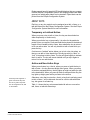
The four basic function keys provide convenient one-touch access to
such basic intercom functions as turning the microphone on and off.
Located on the leftmost side of a function key module, the keys are
labeled as follows:
• GN MIC (gooseneck microphone on/off)
• HS MIC (headset microphone on/off)
• SPKR ON (speaker on/off)
• LISTEN (listen-only/call signal/remote telephone release)
Figure 2-1 illustrates the location and purpose of the basic function
keys. A more detailed discussion of each key follows.
This key turns gooseneck microphone on and off.
This key turns headset microphone on and off.
This key functions only when a headset is present.
It turns the panel's speaker on and off.
MAIN
2
ABC
3
5
JKL
6 MNO
7 PQRS
8
TUV
9 WXYZ
RED
0
CLR
#
GN MIC
1
HS MIC
4
SPKR ON
LISTEN
*
GHI
DEF
VOL / PROG
GRN
Listen Key has three functions.
See Listen Level section in text
for more information.
Figure 2-1: Basic Function Keys
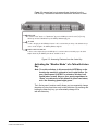
TURNING THE GOOSENECK MICROPHONE ON AND
OFF
The gooseneck microphone key, labeled “GN MIC,” turns your panel’s
gooseneck microphone on or off. Press once to turn the microphone
on; press again to turn the microphone off.
The gooseneck microphone is your panel’s default microphone unless
a headset is plugged in. When a headset is plugged in, an
auto-sensing circuit in the panel automatically turns the headset
microphone on and turns the gooseneck microphone off. The headset
microphone always takes precedence over the gooseneck
microphone.
If you press a talk key while the gooseneck microphone is plugged in
but off, the gooseneck microphone automatically turns on for the
Clear-Com Communication Systems
I-Series Instruction Manual
2-1
duration of the call. The GN MIC key glows dim green whenever the
gooseneck microphone is present but off and bright green whenever
the microphone is present and on. If a gooseneck microphone is not
present, the GN MIC key will not illuminate. Table 2-1 summarizes the
key colors for active and non-active microphone and speaker keys.
TURNING THE HEADSET MICROPHONE ON AND
OFF
The headset microphone key, labeled “HS MIC”, turns your panel’s
headset microphone on and off. Press once to turn the microphone on;
press again to turn the microphone off.
When a headset is plugged in to the panel, the headset microphone
automatically becomes active and the gooseneck microphone is
switched off. To switch to the gooseneck microphone, press the
gooseneck microphone key, labeled “GN MIC.” When the headset is
unplugged, the gooseneck microphone automatically becomes active.
The HS MIC key glows dim green whenever a headset microphone is
present but off, and bright green whenever a headset microphone is
present and on. When a headset microphone is not present, the key
will not illuminate. Table 2-1 on page 7 summarizes the key colors for
active and non-active microphone and speaker keys.
TURNING THE SPEAKER ON AND OFF
The speaker on/off key, labeled “SPKR ON,” functions only when a
headset is plugged into the panel. Pressing the speaker on/off key
toggles the headset speaker on and off. Press the key once to turn the
headset speaker off, and again to turn the headset speaker back on.
As the headset speaker turns off, the panel speaker will turn on and
vice versa.
The key glows dim green whenever the headset speaker is off, and
bright green whenever the headset speaker is on.
Note: Unlike the microphones, both speakers can never be turned
off at the same time. The panel loudspeaker is always active
unless a headset or alternative speaker source has replaced
it. That is why this key is non-functional when a headset is
not plugged in.
USING THE “LISTEN” KEY TO ACCESS
FUNCTIONS
The LISTEN key has three functions:
• Activates the “monitor mode” of a “talk-with-listen” key
• Sends call signals
• Releases remote telephone lines
2-2
Clear-Com Communication Systems
I-Series Instruction Manual
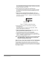
Figure 2-2 summarizes how to access these functions from the
LISTEN key. The sections that follow discuss the functions in detail.
1
MONITOR MODE
To activate the "listen" function of a "talk-with-listen" key, press the LISTEN key less than five seconds ("tap" the key)
and then tap the desired "talk-with-listen" key. The LISTEN key illuminates bright green.
2
CALL SIGNAL
To send a call signal, press the LISTEN key for between 1 and 5 seconds and then press the key of the destination that you
want to send the call signal to. The LISTEN key illuminates bright red.
3
RELEASE A REMOTE TELEPHONE LINE
To release a remote telephone line, press the LISTEN key for 5 seconds and continue to hold while you press the desired
telephone interface key. The LISTEN key turns dim red and flashes on and off.
Figure 2-2: Accessing Features from the Listen Key
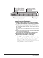
Activating the “Monitor Mode” of a Talk-with-Listen
Key
Note: To avoid confusion, in this manual the LISTEN key on the
function-key module is referred to in all capital letters. On
your i-Series panel “LISTEN” is printed on this key in all
capital letters as well. Keys on your panel programmed to
“listen” are referred to in this manual in lower-case letters,
as in “the listen key glows bright green.”
The i-Series panel “monitor mode” allows you to momentarily change
the status of a key from listen-only to talk-with-listen. By pressing and
holding the listen-only key, you momentarily change it to a
talk-with-listen key.
Clear-Com Communication Systems
I-Series Instruction Manual
2-3
2
All keys assigned as "talk-with-listen" glow dim green. Tap a key to change it to listen-only.
The key glows bright green to indicate that it has changed to listen-only status.
3
To talk to the source, press and hold the key. It reverts to talk-with-listen status (bright red)
only while you hold the key. When you release the key, it reverts back to its liste-only status (bright green).
1
Tap the LISTEN key for less than 1 second.
Figure 2-3: Activating the “Monitor Mode” of a Talk-with-Listen Key
You can scroll one item at a
time through items in a
displayed list by pressing the
CLEAR key to scroll up and
the ANSWR key to scroll
down.
To activate the “monitor mode” of a talk-with-listen key:
1. Press the LISTEN key on the function key module for less than one
second (“tap” the key).
• Each key assigned as a talk-with-listen glows dim green to
indicate that its “monitor mode” is available for activation.
• The LISTEN key on the function key module glows bright green
while in this mode.
2. Tap a dim-green key to activate it.
The key glows bright green to indicate its change to an active
listen-only key.
3. To talk to the source, press and hold the key.
The key glows bright red to indicate that a talk-with-listen call is
active. When you release the key, it reverts back to its active
listen-only mode (bright green). The talk-with-listen function cannot
be latched; it is only active while you press the key.
To cancel the key’s monitor mode and revert back to the
talk-with-listen mode:
1. Tap the LISTEN key on the function-key module.
2. Tap the desired active listen-only key (bright green).
The formerly active listen-only key now glows dim red to indicate
that it has reverted back to its non-active talk-with-listen mode. If you
press the key to talk, it glows bright red.
Note: You must tap the LISTEN key on the function key module
for each key you activate in “monitor mode.”
Sending Call Signals
A call signal is an electronic signal that is sent from one panel or
interface to another to get a panel operator’s attention. It can be used
2-4
Clear-Com Communication Systems
I-Series Instruction Manual
for a variety of more technical purposes as well, such as to activate a
relay to open a door, set off an alarm, or activate a public address (PA)
system.
In order to use this facility the destination panel's Call Signal Tone
must be enabled. This is done in ECS via the Setup Matrix Hardware
facility using “Advanced Settings” and “Audible Alerts” for the
destination panel or panels. The “Call Signal Tone” option must be set
to “True”.
To send a call signal:
1. Press and hold the LISTEN key for between 1 and 5 seconds. The
LISTEN key turns bright red to indicate that you have entered the
“call-signal send” mode.
2. Press the key of the destination that you want to send the call signal
to.
A call signal of three loud beeps is sent to a destination each time
that you press the destination’s key.
3. To send a call signal to a new destination, press the new
destination’s key.
A call signal is sent to the new destination each time you press that
destination’s key.
4. To exit “call-signal send” mode, tap the LISTEN key and release.
• You can also exit “call-signal send” mode by simply not pressing a
display key for five seconds. The mode will automatically
time-out.
• When you exit “call-signal send” mode, the LISTEN key changes
from bright red to no illumination.
You can send a call signal to any destination with a designated key on
your panel. If more than one destination is assigned to a key, each
destination will receive the call signal. If the destination is a party line,
then every panel listening on the party line will receive the call signal.
Note: The call signal is sent at the page-override volume level,
which is programmable in the Eclipse Configuration
System. For more information, see the Eclipse
Configuration System Manual.
Releasing Remote Telephone Lines
To release a telephone interface that has been left off-hook:
1. Enable “remote telephone release” for that panel in the Eclipse
Configuration System.
Often this feature will already be set up in the configuration system
software. For more information, refer to the Eclipse Configuration
System Manual.
2. Press and hold the LISTEN key for more than 5 seconds.
The LISTEN key turns bright green and flashes on and off.
Clear-Com Communication Systems
I-Series Instruction Manual
2-5
3. While still holding the LISTEN key, press the desired telephone
interface key on any key module.
The telephone interface will hang up. All audio paths to and from the
telephone interface will be deactivated.
4. Release the LISTEN key to exit.
2-6
Clear-Com Communication Systems
I-Series Instruction Manual
SUMMARY OF FUNCTION KEY MODULE LIGHTS
Table 2-1 summarizes the meanings of the colors and blink rates for all
the keys on the function key module.
GN MIC KEY
Gooseneck mic off
Gooseneck mic on
HS MIC KEY
Headset not present
Headset present and off
Headset present and on
SPKR ON KEY
Speaker on
Speaker off
LISTEN KEY
No function
Listen-only call mode
Call-signal send mode
Remote telephone hang-up
0–9, *, # KEYS
No function
Key pressed or mode active
Dial mode
Dial mode and key pressed
KEY COLOR
dim green
bright green
KEY COLOR
off
dim green
bright green
KEY COLOR
dim green
bright green
KEY COLOR
off
bright green
bright red
bright green
KEY COLOR
off
bright green
dim red
bright red
BLINK RATE
none
none
BLINK RATE
none
none
none
BLINK RATE
none
none
BLINK RATE
none
none
none
1x per second
BLINK RATE
none
none
none
none
Table 2-1: Colors and Blink Rates for Keys on Function Key Module
Clear-Com Communication Systems
I-Series Instruction Manual
2-7
2-8
Clear-Com Communication Systems
I-Series Instruction Manual
3
You access the advanced
features from the function
module’s numeric keypad or
from the feature menu.
ACCESSING I-SERIES
ADVANCED
FUNCTIONS
i-Series intercom panels have advanced features that you access in
one of the following two ways:
• By pressing the number key associated with the feature. For
example, when you press the “1” key on the numeric keypad, you
enter “telephone dialing” mode. Figure 3-1 shows the features
associated with each number key on the numeric keypad. A fuller
discussion of each feature follows.
• By scrolling through the feature menu. For example, you can
scroll through the feature menu, and select “dial” to access the
“telephone dialing” mode. The advantage of a menu is that you
do not have to memorize each available key function. See
“Selecting Features from the Menu” later in this chapter for more
information.
Most of the features are available only when a panel is connected to
the matrix, but some are available even when a panel is not connected
to the matrix. The requirements for each feature are given in the
following sections. Figure 3-1 and Table 3-1 below lists features and
identify which number keys on the keypad are associated with each.
1 Dial
2 Local Exclusive
Local Key Assignments 5
MAIN
IFB, Party Line,
Fixed Group assign 4
GN MIC
1
HS MIC
4
SPKR ON
Local Preferences 7
LISTEN
GHI
2
ABC
3
5
JKL
6 MNO
DEF
7 PQRS
8
TUV
9 WXYZ
RED
0
CLR
#
*
6 Shift Page
VOL / PROG
9 Port Information
GRN
# Enter
0 Clear
*
Escape or Cancel
Figure 3-1: Features Accessed by Keys on the Numeric Keypad
Clear-Com Communication Systems
I-Series Instruction Manual
3-1
OVERVIEW OF ADVANCED FEATURES
KEY
1
FUNCTION
DESCRIPTION
Dial
Enters telephone dialing mode.
2
Local Exclusive Enters mode to temporarily deactivate all
keys except the one being used.
3
Local Page
Enters mode to override current on/off and
Override
volume settings at a destination.
4
IFB, Party Line Enters the setup mode for IFB, Party Line
and Fixed
and Fixed Group to allow sources to be
Group assign- assigned as IFBs, or to Party Lines or Fixed
ment
Groups.
5
Local Key
Enters mode to assign sources and destiAssignments
nations in the system to keys on your
panel.
6
Swap Page
Switches between the panel main page and
the swap page.
7
Local PreferEnters the setup mode to adjust Listen
ences
Level Reset, Panel Mic Level, Headset Mic
Level, Sidetone Level and Listen Level
Adjust.
9
Port Information Gives you the panel’s port number, label,
associated CPU card, and current firmware
version number.
0 CLR
Clear
Clears the current display entry and takes
you back to the previous menu.
* RED
Escape or Can- Abandons all unsaved programming and
cel
returns the panel to normal use.
# GRN
Enter
Saves the current programming changes
and reverts the panel to normal use.
VOL/PROG Display ConAllows you to adjust contrast lighting on distrast Adjust
plays and to adjust the panel’s baud rate
KNOB
Baud Rate
Adjust
Table 3-1: Advanced Key Functions
TELEPHONE DIALING FROM THE KEYPAD (#1 KEY)
You can dial from the keypad on a function key module as if you were
dialing from a standard telephone keypad. When you press the
number keys, standard DTMF tones are generated to all active talk key
destinations. Note that this feature is only available when the central
matrix is connected and online.
3-2
Clear-Com Communication Systems
I-Series Instruction Manual
1b
When you complete step 1,
the word "dial" appears in
the display.
4
2
Press keys on the numeric keypad to
generate DTMF tones to all active talk
key destinations.
Press the CLEAR key to exit dialing mode.
1a
Press the "1" key on
the numeric keypad to
enter dialing mode.
Figure 3-2: Telephone Dialing from the Function Keypad Module
To generate standard DTMF tones to all active talk key destinations:
1. Press the “1” key on the keypad to enter dialing mode.
• The keypad becomes a telephone touch-tone dialing pad.
• The word “dial” appears in the display below the “CLEAR” key.
• All 12 valid dialing keys on the keypad glow dim red.
To select an item with the
VOL/PROG knob, press the
knob in, as you would press a
key, when the desired item
appears in the display.
2. Press keys on the numeric keypad (0–9, *, #) to generate standard
DTMF tones to all active talk-key destinations.
3. Press the “CLEAR” key to exit dialing mode.
Dialing mode automatically times out if you do not press a key on
the numeric keypad (0–9, *, #) for five seconds.
ACCESSING LOCAL EXCLUSIVE (#2 KEY)
When you activate the “local exclusive” feature, all previously latched
keys on your panel deactivate temporarily while you either talk to one
destination or listen to one source. Note that the “local exclusive”
feature is only active when the matrix is connected and online.
To activate the local exclusive function:
1. Press the “2” key on the keypad to enter “local exclusive” mode.
2. Press and release any talk or listen key (even an already latched
key).
• When you press and release a talk or listen key, all previously
latched keys (both talks and listens) deactivate temporarily, and
you can talk or listen from that key exclusively.
• The feature is only active while the key is latched in “local
exclusive” mode.
• The “2” key on the keypad will glow bright green while this feature
is active.
Clear-Com Communication Systems
I-Series Instruction Manual
3-3
3. To exit “local exclusive” mode press the key you pressed in step 2
again to deactivate it.
• The previously latched keys will return to their active state.
• This feature does not work on the answer-back (ANSWR) key.
You can also select this feature from the menu. See “Accessing
Feature Menus” later in this chapter for more information.
LOCAL PAGE OVERRIDE (#3 KEY)
The “local page override” feature allows you to talk to one or more
destination panels regardless of the on/off or volume settings at each
panel’s speaker. The feature literally “overrides” the current on/off and
volume settings at the destination.
You can adjust the local page override’s volume level in the Eclipse
Configuration System program. By default, the volume is set up at 5 on
a 1–10 scale, but it can be adjusted to any value on the scale.
Note that this feature is only active when the Matrix is connected and
online.
To activate local page override:
1. Press “3” on the keypad to enter “local page override” mode.
2. Press any talk key (even an already latched key).
• You can talk to all destinations associated with that key. The
current on/off settings and volume levels will be overridden at
those panels’ speakers.
• The “3” key on the keypad will glow bright green while this feature
is active.
• Local page override does not work from the answer-back
(ANSWR) key.
3. To exit “local page override,” release the pressed talk key.
Local page override mode automatically times out if you do not
press a key on the function-key module for five seconds.
You can also enter the “local page override” mode by selecting it from
the feature menu. See “Accessing Feature Menus” later in this chapter
for more information.
Note that if a key cannot be page overridden because it is assigned as
an interface or party line, there will not be an error message to indicate
that the function is not available on that key.
IFB, PARTY LINE AND FIXED GROUP ASSIGNMENTS
(#4 KEY)
The “4” key allows local assignments to be made for IFBs, Party Lines
and Fixed Groups. To access the assignment mode:
3-4
Clear-Com Communication Systems
I-Series Instruction Manual
• Press the “4” key. The “CLEAR” key will illuminate red and “IFB”
will be displayed below it.
• To access Party Line mode press the “CLEAR” key. “PL” will be
displayed below it.
• To access Fixed Group mode press the “CLEAR” key again. “FG”
will be displayed below it.
• Pressing the “CLEAR” key again will exit assign mode.
Setting Up IFB Sources and Destinations on an
i-Series panel
Only Global IFBs with Talk are valid as IFB destinations and only
sources with listen are valid to be assigned to an IFB.
1. Press the “4” key so that the “CLEAR” key illuminates red and “IFB”
is displayed below it.
2. All valid IFB destinations will flash red.
3. Press the front-panel button for the required IFB destination. Its light
turns solid red, while all valid sources’ lights blink green.
4. Press a source’s button to assign it to the destination. Its light turns
solid green. Pressing the button again deactivates the assignment.
5. Repeat steps 3 and 4 until all sources are assigned to the IFB
destination.
6. Press the “CLEAR” button three times to exit IFB mode.
Setting Up Party Line members on an i-Series panel
Only Talk and Listen keys are valid as members of a Party Line.
1. Press the “4” key so that the “CLEAR” key illuminates red and “IFB”
is displayed below it.
2. Press the “CLEAR” key so that “PL” is displayed below it.
3. All available Party Lines flash red.
4. Press the key for the desired Party Line.
5. The key’s light becomes solid red and all available members’ lights
flash green.
6. Press a key with the associated flashing green light of an available
member to add it to the Party Line.
7. The light becomes solid green to indicate the member has been
added to the Party Line.
8. To remove a member from the Party Line, press that member’s key.
The solid green light associated with that key blinks green to
indicate it is now available.
9. Repeat steps 6 and 7 until the Party Line contains all desired
members.
10. Press the “CLEAR” key twice to exit Party Line mode.
Clear-Com Communication Systems
I-Series Instruction Manual
3-5
Setting Up Fixed Group members on an i-Series
panel
Only Talk and Listen keys are valid as members of a Fixed Groups.
1. Press the “4” key so that the “CLEAR” key illuminates red and “IFB”
is displayed below it.
2. Press the “CLEAR” key again so that “PL” is displayed below it.
3. Press the “CLEAR” key again so that “FG” is displayed below it.
4. All available Fixed Groups flash red.
5. Press the key for the desired Fixed Group.
6. The key’s light becomes solid red and all available members’ lights
flash green.
7. Press a key with the associated flashing green light of an available
member to add it to the Fixed Group.
8. The light becomes solid green to indicate the member has been
added to the Fixed Group.
9. To remove a member from the Fixed Group, press that member’s
key.
The solid green light associated with that key blinks green to
indicate it is now available.
10. Repeat steps 7 and 8 until the Fixed Group contains all desired
members.
11. Press the “CLEAR” key to exit Fixed Group mode.
LOCAL KEY ASSIGNMENT (#5 KEY)
The “pick list scroll” feature allows you to assign any intercom panel or
interface in the system to a key on your panel directly from your panel.
You can assign the panel or interface to your panel as a talk key, a
listen key, or a talk-with-listen key.
To do this, you first access a list of all panels and interfaces in the
system on the front-panel display of your i-Series panel. You then
scroll through the list and select the panel or interface that you want to
assign to your panel. In other words, you literally “pick” from a “list” that
you “scroll” through. This feature is only available when the Matrix is
connected and online.
Two procedures are described below. The first describes how to assign
a remote destination to your panel as a “talk” or “talk-with-listen” key.
The second describes how to assign a remote source to your panel as
a “listen” key.
3-6
Clear-Com Communication Systems
I-Series Instruction Manual
A list of current destinations in the system appears
in the leftmost display on the panel. Scroll through
the list. See the procedure for more information.
2
4
3
When the desired destination appears in the display,
select it by pressing the VOL/PROG knob in, as if it were a key.
Assign the selected remote panel or interface to a key on your
panel by tapping the desired key for less than 1/2 second to assign it
as a "talk" or for more than 1/2 second to assign it as a "talk-with-listen."
1
Press the "5" key on
the numeric keypad.
Figure 3-3: Assigning a Remote Destination to a Talk or Talk-with-Listen Key
To assign a remote destination to a key on your panel as a “talk”
or “talk-with-listen”:
1. Press the “5” key on the numeric keypad to enter “pick list scroll”
mode.
• A list of current panels and interfaces in the system that are
available to assign as “talk” keys (or as “talk-with-listen” keys) is
displayed starting in leftmost key module’s display window.
• The lists are sorted alphanumerically—with symbols first, then
numbers, then letters. You can jump to the desired alphabetical
area of the list by pressing the corresponding “letter” key on the
keypad. Press the “A” key to jump to the first label that begins with
an “A,” press the “B” key to jump to the first label that begins with
a “B,” and so on.
2. Scroll through the list of current available “talks” and “listens” by
rotating the PROG/VOL knob.
You can also scroll one horizontal line at a time by pressing the
CLEAR key to scroll up the list and the ANSWR key to scroll down
the list.
3. Select the desired panel or interface when it is highlighted in the
display by pressing in and releasing the VOL/PROG knob.
4. Assign the selected remote panel or interface to a key on your panel
by either tapping or pressing the desired key.
• Tap a key for less than 1/2 of a second to assign it as a talk-only.
• Press a key for more than 1/2 of a second to assign it as a
talk-with-listen key.
5. After you have completed assigning keys, exit “pick list scroll” mode
by pressing the ESCAPE key (labeled “*RED”). To exit the current
menu only, and return to the previous menu, press the
FUNCTION-CLEAR key (labeled “0 CLR”).
Clear-Com Communication Systems
I-Series Instruction Manual
3-7
Note: If PIN codes are set up in the Eclipse Configuration System
you must enter one of the four possible 4-digit PIN codes
before entering Local Key Assignment mode. The display
will ask for the PIN code at which time you must enter the
correct 4-digit code.
A list of current sources in the system appears
in the leftmost display on the panel. Scroll through
the list. See the procedure for more information.
2
4
3
When the desired source appears in the display,
select it by pressing the VOL/PROG knob in, as if it were a key.
Assign the selected remote panel or interface to a key on your
panel by pressing the desired key. The key glows dim green. The
new label appears in the display.
1
Press the "5" key on
the numeric keypad.
Figure 3-4: Assigning a Remote Source to a Listen Key
To assign a remote source to a key on your panel as a “listen”:
1. Press the “5” key on the numeric keypad to enter “pick list scroll”
mode.
A list of current panels and interfaces in the system that are
available to assign as “talk” keys (or as “talk-with-listen” keys) is
displayed starting in the leftmost key module’s display window.
2. Press the LISTEN key to display a list of current panels and
interfaces in the system that are available to assign as “listen” keys.
The list is sorted alphanumerically—with symbols first, then
numbers, then letters. You can jump to the desired alphabetical area
of the list by pressing the corresponding “letter” key on the keypad.
Press the “A” key to jump to the first label that begins with an “A,”
press the “B” key to jump to the first label that begins with a “B,” and
so on.
3. Scroll through the list of current available “listens” by rotating the
PROG/VOL knob.
You can also scroll one horizontal line at a time by pressing the
CLEAR key to scroll up the list and the ANSWR key to scroll down
the list.
4. Select the desired panel or interface when it is highlighted in the
display by pressing in and releasing the VOL/PROG knob.
5. Assign the selected remote panel or interface to a key on your panel
by either tapping or pressing the desired key.
The key glows green to indicate it is a “listen” and its new label
appears in the display.
3-8
Clear-Com Communication Systems
I-Series Instruction Manual
6. After you have completed assigning keys, exit “pick list scroll” mode
by pressing the ESCAPE key (labeled “*RED”). To exit the current
menu only, and return to the previous menu, press the
FUNCTION-CLEAR key (labeled “0 CLR”).
Note: If PIN codes are set up in the Eclipse Configuration System
you must enter one of the four possible 4-digit PIN codes
before entering Local Key Assignment mode. The display
will ask for the PIN code at which time you must enter the
correct 4-digit code.
To clear a key’s “talk” assignment on your panel:
1. Press the “5” key on the numeric keypad to enter “pick list scroll”
mode.
• A list of current talks (destinations) in the system is displayed
starting in the leftmost key module’s display window.
• The first item on the talk list is “clear.” It should be highlighted to
indicate that it is available to be selected.
2. When the word “clear” is highlighted in the display, select it by
pressing in and releasing the VOL/PROG knob.
The leftmost module’s display window will revert to showing
currently assigned sources and destinations.
3. Tap the key with the talk assignment that you want to clear.
You will hear a confirmation tone of two loud beeps to indicate that
the key’s assignment is cleared. The key’s label will disappear from
the display and the key itself will not illuminate.
To clear a key’s “listen” assignment on your panel:
1. Press the “5” key on the numeric keypad to enter “pick list scroll”
mode.
A list of current talks (destinations) in the system is displayed
starting in the leftmost key module’s display window.
2. To display a list of all listens (sources) in the system, press the
LISTEN key.
A list of current listens (sources) in the system is displayed starting
in the leftmost key module’s display window.
3. The first item in the listens list is “clear.” It should be highlighted to
indicate that it is available to be selected.
4. When the word “clear” is highlighted in the display, select it by
pressing in and releasing the VOL/PROG knob.
The leftmost module’s display window will revert to showing
currently assigned sources and destinations.
5. Tap the key with the listen assignment that you want to clear.
You will hear a confirmation tone of two loud beeps to indicate that
the key’s assignment is cleared. The key’s label will disappear from
the display and the key itself will not illuminate.
Clear-Com Communication Systems
I-Series Instruction Manual
3-9
SWAP PAGE (#6 KEY)
The “6” key toggles between the main page and the swap page.
Pressing the “6” key with the main page displayed (normally the default
panel state) causes the main panel assignments to be replaced by the
swap page assignments.
Pressing the “6” key again reverts to the main page display.
LOCAL PREFERENCES (#7 KEY)
The “local preferences” feature allows you to adjust your panel’s
volume settings, including:
• Resetting listen levels to the default
• Adjusting the gooseneck microphone volume level
• Adjusting the headset microphone volume level
• Adjusting the sidetone volume level
This feature is only active when the Matrix is connected and online. An
illustration and description of how to operate the local preferences
feature follows. Each local preference is described in its own section.
A list of local preferences appears in the display.
Scroll through the list. See the procedure for more
information on scrolling.
2
4
3
When the desired local preference appears in
the display, select it by pressing the VOL/PROG
knob in, as if it were a key.
Follow the instructions in the display
to set local preferences. To exit local
preferences mode, press the # key.
1
Press and release the "7"
key on the numeric keypad.
Figure 3-5: Adjusting Local Preferences
To adjust a “local preference”:
1. Press the “7” key on the numeric keypad to enter “local preferences”
mode.
A list appears in the leftmost display of the panel. You have a choice
of five items: (1) listen level reset, (2) gooseneck mic volume level
reset, (3) HS mic volume level reset, (4) sidetone volume level reset,
and (5) exit. These options are described in detail immediately
following step 5.
2. Scroll through the list by rotating the VOL/PROG knob.
You can also scroll one item at a time by pressing the CLEAR key to
scroll up the list and the ANSWR key to scroll down the list.
3-10
Clear-Com Communication Systems
I-Series Instruction Manual
3. When the desired item appears in the display above the ANSWR
key, select it either by pressing the VOL/PROG knob in, or by
pressing the ENTER key (labeled “#GRN”).
4. Follow the directions in the display. Additional instructions for setting
individual local preferences are given following step 5. Go to the
section for the individual local preference you are adjusting.
5. To exit “local preferences” mode, press the ESCAPE key (labeled
“*RED”) on the function keypad module. To return to the previous
menu without saving any changes, press the “0” key (labeled
“CLR”). You can also select “exit” from the local preferences menu
to exit “local preferences” mode.
LOCAL PREFERENCE OPTIONS
Listen Level Reset
When you select Listen Level Reset, all listen keys are reset to the
default level which is the highest possible volume. The leftmost display
on the panel will read: “Listen Level Reset Sent to Matrix” for one
second. Proceed to step 4 to exit “local preferences” mode.
As you scroll through
gooseneck microphone,
headset microphone, and
sidetone volume levels, you
will be able to hear the
increasing or decreasing
volume levels. To make the
change permanent, however,
you must select the desired
volume level when it appears
in the display by pressing the
ENTER key or the
VOL/PROG knob.
Gooseneck Microphone Volume Level
When you select this menu item, the leftmost display on the panel
shows the current gooseneck microphone volume level, with choices
for increasing or decreasing it. For example, the display may read:
Set Gooseneck Mic Volume Level
+2 dB with increase/decrease choices of:
(+7,+6,+5,+4,+3,+2,+1,0-1,-2,-3,-4,-5,-6,-7,-8)
In this example, the current gooseneck volume level is 2 dB. To
increase the volume, press the ANSWR key. To decrease the volume,
press the CLEAR key. Each time you press either the ANSWR key or
the CLEAR key, you change the volume level by one increment. The
selected volume level is highlighted in the display. You can also
change the volume level by rotating the VOL/PROG knob.
When you reach the desired volume level, press either the ENTER key
(labeled “#GRN”), or press the VOL/PROG knob in, as if it were a key,
to save the information. Then exit “local preferences” mode.
The default outgoing microphone audio level is the highest possible
level of +7 dB.
Note: As you scroll through the volume-level scale, you will hear
the gooseneck microphone’s volume level change
accordingly. To make the change permanent however, you
must select the desired value on the scale by either
pressing in the VOL/PROG knob or by pressing the ENTER
key (labeled “#GRN”) when the value appears in the display.
Clear-Com Communication Systems
I-Series Instruction Manual
3-11
Headset Microphone Volume Level
When you select Headset Microphone Volume Level from the menu,
the leftmost display on the panel shows the current headset
microphone volume level, with choices for increasing or decreasing it.
For example, the display may read:
Set HS Mic Volume Level
+2 dB with increase/decrease choices of:
(+7,+6,+5,+4,+3,+2,+1,0,-1,-2,-3,-4,-5,-6,-7,-8)
In the example above, the current headset volume level is 2 dB. To
increase the volume, you press the ANSWR key, and to decrease the
volume, you press the CLEAR key. Each time you press either the
ANSWR or CLEAR key, you change the volume level by one
increment. The selected volume level is highlighted in the display. You
can also change the volume level by rotating the VOL/PROG knob.
When you reach the desired volume level, either press the ENTER key
(labeled “#GRN”), or press the VOL/PROG knob in, as if it were a key,
to save the information. Then exit “local preferences” mode.
The default outgoing microphone audio level is the highest possible
level of +7 dB.
Note: As you scroll through the volume-level scale, you will hear
the headset microphone’s volume level change accordingly.
To make the change permanent however, you must select
the desired value on the scale by either pressing in the
VOL/PROG knob or by pressing the ENTER key (labeled
“#GRN”) when the value appears in the display.
Sidetone Volume Level
When you select Sidetone Volume Level from the display, the leftmost
display on the panel shows the current sidetone level, with choices for
increasing or decreasing it. For example, the display may read:
Set Sidetone Volume Level
+10 dB with increase/decrease choices of:
(+30, +28, +26, +24, +22, +20, +18, +16, +14, +10, +8, +6,
+4, +2, 0)
In this example, the current sidetone level is 10 dB. To increase the
sidetone, you press the ANSWR key, and to decrease the sidetone,
you press the CLEAR key. Each time you press either the ANSWR or
CLEAR key, you increase the sidetone level by one increment. The
selected volume level is highlighted in the display. You can also
change the sidetone level by rotating the VOL/PROG knob.
When you reach the desired volume level, either press the ENTER key
(labeled “#GRN”), or press the VOL/PROG knob in, as if it were a key,
to save the information. Then exit “local preferences” mode.
3-12
Clear-Com Communication Systems
I-Series Instruction Manual
Note: As you scroll through the volume-level scale, the sidetone
volume level will change accordingly. To make the change
permanent however, you must select the desired value on
the scale by either pressing in the VOL/PROG knob or by
pressing the ENTER key (labeled “#GRN”) when the value
appears in the display.
Exit
When you select the “exit” menu item, you exit “local preferences”
mode. To select the item, scroll to it, then press the VOL/PROG knob
in or press the ENTER key (labeled “#GRN”).
ACCESSING PORT INFORMATION (#9 KEY)
The port information feature gives you the following information about
your panel:
• The panel’s port number at the central matrix
• The panel’s label at the central matrix
• The panel’s current firmware version number
Your panel must be connected to the central matrix to access all of the
port information. If your panel is not connected to the central matrix,
only the panel’s current firmware version number will be displayed.
To obtain port information:
1. Press the “9” key on the numeric keypad to enter “port information”
mode.
The leftmost display on the panel will show the panel’s current
matrix port number, matrix label, and firmware version number.
2. Press the ESCAPE key (labeled “*RED”) to exit.
The display will automatically time out after five seconds.
You can also access this feature through the menu. For more
information, see “Accessing Feature Menus” later in this chapter.
CLEARING THE CURRENT PROGRAMMING
Press the CLEAR key (labeled “0 CLR”) on the numeric keypad to
clear the current entry on the leftmost display and take you back to the
previous menu, if any.
ESCAPING THE CURRENT PROGRAMMING
Press the ESCAPE key (labeled “*RED”) on the numeric keypad to
abandon all unsaved programming and revert the panel to normal use.
Clear-Com Communication Systems
I-Series Instruction Manual
3-13
ENTERING THE CURRENT PROGRAMMING
Press the ENTER key (labeled “#GRN”) on the numeric keypad to
save the current programming changes and revert the panel to normal
use.
ADJUSTING BACKGROUND LIGHTING
You can adjust the background lighting on front-panel displays directly
from your i-Series panel. You can also adjust the panel’s baud rate
directly from the panel.
To adjust background lighting on all front-panel displays on the
panel:
1. Press the VOL/PROG knob in, as if it were a key, for three seconds.
The panel’s leftmost display shows the first two items in a five-item
list: (1) Set Baud Rate, (2) Display Contrast, (3) Module Information,
(4) panel Information, and (5) Exit.
2. Scroll through the list by rotating the VOL/PROG knob.
You can also scroll through the list one item at a time by pressing
the”CLEAR” key to scroll up the list and the “ANSWR” key to scroll
down the list.
3. When the list item “Display Contrast” is highlighted, select it by
pressing in and releasing the VOL/PROG knob, as if it were a key.
A submenu, as shown in Figure 3-6, appears in the display showing
the current contrast value for the panel’s displays.
Current
Contrast
Value
Display
CONTRAST
8
Scroll to increase
or decrease value
Figure 3-6: Submenu of Display Contrast Values
4. Scroll through the range of values by rotating the VOL/PROG knob.
The values range from the lowest contrast value of 0 to the highest
contrast value of 10.
5. When the desired value appears in the display, select it by pressing
the ENTER key (labeled “#GRN”).
The selected value goes into effect immediately.
6. Exit from the submenu by pressing the ESCAPE key (labeled
“*RED”). To escape the submenu and return to the previous menu,
press the CLEAR key (labeled “CLR”).
To change the panel’s baud rate:
1. Press the VOL/PROG knob in, as if it were a key, for three seconds.
3-14
Clear-Com Communication Systems
I-Series Instruction Manual
The panel’s leftmost display shows the first two items of a five item
list: (1) Set Baud Rate, (2) Display Contrast, (3) Module Information,
(4) Panel Information, and (5) Exit.
2. Scroll through the list by rotating the VOL/PROG knob.
You can also scroll through the list one item at a time by pressing
the CLEAR key to scroll up the list and the ANSWR key to scroll
down the list.
3. When the list item “Set Baud Rate” is highlighted, select it by
pressing in and releasing the VOL/PROG knob, as if it were a key.
A submenu, as shown in Figure 3-7, appears in the display showing
the current baud rate.
Set Baud Rate
19,200 Default
Current baud rate
Scroll to increase
or decrease value
Figure 3-7: Submenu of Baud Rate Values
4. Scroll through the submenu of baud rates by rotating the
VOL/PROG knob.
The submenu gives you a choice of four baud rates: 19,200
(Default), 9600, 4800, and 2400 baud.
5. When the desired baud rate appears in the display, select it by
pressing the ENTER key (labeled “#GRN”).
The selected baud rate goes into effect immediately.
6. Exit from the submenu by pressing the ESCAPE key (labeled
“*RED”). To escape the submenu and return to the previous menu,
press the CLEAR key (labeled “0 CLR”).
Note: The Eclipse MVX-A16 card does not accept anything other
than 19k2 baud rate. These baud rates are useful when
used with 3rd party interfaces only).
SELECTING A FEATURE FROM THE FEATURE MENU
The advantage of using the menus is that you can see all of the
available features listed and then select the desired feature simply by
pressing the VOL/PROG knob when the feature’s menu item appears
in your panel’s display.
Clear-Com Communication Systems
I-Series Instruction Manual
3-15
2
4
The leftmost display on the panel will show
the first two menu items. To scroll through the
menu items, either turn the VOL/PROG knob,
or press the CLEAR key to scroll up the list
and the ANSWR key to scroll down the list.
3
When you reach the desired menu item,
push the VOL/PROG knob in, as if it were
a key, to select the item.
After you select an item from the list, follow the
instructions in the manual to use the feature.
1
To access the menu,
press the # key.
Figure 3-8: Selecting a Feature from the Feature Menu
To select a feature from the feature menu:
1. Press the ENTER key (labeled “#GRN”) on the numeric keypad.
The leftmost display on the panel will show the first two menu items.
2. Scroll through the menu items by pressing the “ANSWR” key to
scroll down the list and the “CLEAR” key to scroll up the list. Each
time you press the “ANSWR” key or the “CLEAR” key, you scroll one
item on the list.
You can also rotate the VOL/PROG knob to scroll through the menu
items.
3. When you reach the desired menu item, press the VOL/PROG knob
in, as if it were a key, to select the item.
To exit from the menu, press the ESCAPE key (labeled “*RED”).
4. After you select a feature, follow the instructions from the
appropriate section in this chapter to use the feature.
Note: You can also select a menu item simply by first pressing
the ENTER key (labeled “#GRN”), then pressing the number
key that corresponds to the menu item—for example, the 1
key for the first menu item, the 2 key for the second menu
item, and so on. This method is often quite faster than
scrolling through several menu items to select an item. The
same procedure can be used for submenus.
3-16
Clear-Com Communication Systems
I-Series Instruction Manual
4
CONNECTING TO AN
ECLIPSE MATRIX, TO
AC POWER, AND TO
AUDIO OPTIONS
REAR-PANEL MODULES
You connect an i-series intercom panel to the central matrix, to audio
options, and to an expansion panel through the connectors located on
the panel’s rear panel. The connectors are organized into the following
two modules:
• The communications module, which is standard on all i-series
intercom panels. This module connects an i-Series panel to the
central matrix and, if required, to an expansion panel.
• The auxiliary options module, which as its name implies, is
optional. This module connects an i-Series panel to a variety of
audio and control functions. The functions available from this
module are described later in this chapter.
The panel’s rear panel also contains an AC power connector to the
panel’s internal universal AC power supply.
Figure 4-1 illustrates the rear panel of an i-series intercom panel.
AC - IN
HMO
J8
90 - 245 V
PROG
J9
J5A/GPI
MIC
J 10
EXPANSION
OUT
SPKR
LINE
OUT
J6
J7
J2
TO MATRIX
J3
J5B/RELAY
AC POWER CONNECTOR
AUXILIARY OPTION MODULE
J1
COMMUNICATIONS MODULE
Figure 4-1: Rear Panel of an i-Series Intercom Panel
AC POWER
The leftmost connector in the illustration, labeled “AC Power
Connector,” connects the panel to the internal universal AC power
supply. The power supply operates over a voltage range of 90 to 245
VAC and a frequency range of 45 to 65 Hz. The maximum power input
is 60 watts, with 30 watts typical and 30 A (amps) peak inrush.
Clear-Com Communication Systems
I-Series Instruction Manual
4-1
COMMUNICATIONS MODULE
The communications module connects an i-Series panel to the central
matrix and to an expansion panel. There are three connectors on the
communications module, labeled J1 through J3, as shown in Figure
4-2.
J2 DB-15 reserved for
future use
J1 RJ-45 connects to
expansion unit
J3 RJ-45 connects
to Eclipse frame
EXPANSION
OUT
J 2 TO MATRIX
J3
J1
Figure 4-2: Communications Module Connectors
J1
Expansion Out Connector
The connector labeled J1 is an RJ-45F that connects the i-Series panel
to an expansion panel. Shielded category-5 cable is required.
J2
DB-15M Connector (Reserved for Future Use)
The connector labeled J2 is a DB-15M connector reserved for future
use.
J3
To Matrix Connector
The connector labeled J3 is an RJ-45F that connects the i-Series panel
to an Eclipse matrix frame. Shielded category-5 cable is required.
AUX-101 AUXILIARY OPTIONS MODULE
The auxiliary options module connects your i-Series panel to the
following audio and control inputs and outputs:
• General purpose inputs
• Relay outputs
• Speaker-feed output
• Line-level output
• Hot-microphone output
• Program input
• Auxiliary microphone input
4-2
Clear-Com Communication Systems
I-Series Instruction Manual
Figure 4-3 shows the location of each connector on the auxiliary
options module.
General Purpose Inputs DB-15 connector
J5A
Relay Outputs DB-15 connector
J5B
Hot-Microphone Out
A3M-type connector
External Dynamic Microphone
A3F-type connector
J8
HMO
J8
J5A/GPI
J5B/RELAY
External Speaker Input
Tip/Ring 1/8-inch mini-connector
J6
Line-Level Output
Tip/Ring/Sleeve 1/8-inch mini-connector
J7
SPKR
LINE
OUT
J6
J7
J10
PROG
J9
MIC
J 10
Program Input J9
A3F-type connector
Figure 4-3: Auxiliary Options Module Connectors
J5A
General Purpose Inputs Connector
The DB-15F connector labeled “J5A” connects your i-Series panel to
two local general purpose inputs (GPIs). The remaining six local
general purpose inputs are reserved for future use.
The general purpose inputs connector is provided so that you can
connect an external logic device—such as an external foot switch, a
panel-mounted switch, or the logic output of some other device—to
your panel.
When the external logic device is activated, it sends a control signal
into your panel’s microprocessor to perform one of several preset
functions. such as turning the panel’s microphone off or on, muting the
microphone’s output, or turning the panel’s speaker off. You choose
the function to be performed from the Eclipse Configuration System
under “Advanced Settings” in the “Logic Inputs” menu. This allows the
logic inputs to be configured from a drop-down list of items described
below.
Before wiring a logic device to the GPI connector, you must first select
the logic device’s function in the Eclipse Configuration System. For
more information, refer to the Eclipse Configuration System Manual.
The setting options are:
• Microphone On/Off
• Mute Mic Output to Frame
• Microphone Off (Momentary)
• Answerback Talk/Clear
• Studio Announce
Clear-Com Communication Systems
I-Series Instruction Manual
4-3
• Speaker Off
• PTT: Activate All Talk Keys
• Activate Talk Switch #1
• Activate Talk Switch #2
With the GPI connector, you
can connect an external logic
device—such as an external
foot switch, a panel-mounted
switch, or the logic output of
some other device—to your
panel.
• Activate Listen Labels
• PTT: Activate Two-Way Radio Talk Keys
These settings are described in detail in the following sections.
Microphone On/Off (Toggle)
The “Microphone On/Off” function allows you to set up an external
logic device, such as a panel-mounted switch, a foot switch, or the
logic output of some other device, to shut the panel’s microphone on or
off.
To use a logic device to turn the panel’s microphone off and on:
1. Select the “Microphone On/Off” option in the Eclipse Configuration
System.
2. Connect a logic device (such as a foot switch, a panel-mounted
switch, or the logic output of another device) to the i-Series panel’s
GPI connector.
3. Switch on the logic device to turn the panel’s microphone on. Switch
off the logic device to turn the panel’s microphone off.
Mute Microphone Output to Frame
The “Mute Mic Output to Frame” function allows you to set up an
external logic device, such as a panel-mounted switch, a foot switch,
or the logic output of some other device, to shut off the audio going
from the panel to the matrix frame.
Note that this feature does not turn off the “hot-microphone” output
described later in this chapter. The A3M standard XLR connector
labeled “J8” on the back of your i-Series panel is the hot-microphone
output connector. It provides a line-level output of the selected
microphone’s audio (headset or panel) that is always “on” (or “hot”).
Only the panel’s microphone on/off key can override this output.
To use a logic device to shut off the audio going from the panel to
the frame:
1. Select the “Mute Mic Output to Frame” option in the Eclipse
Configuration System.
2. Connect a logic device (such as a foot switch, a panel-mounted
switch, or the logic output of another device) to the i-Series panel’s
GPI connector.
3. Switch on the logic device to shut off the audio going from the panel
to the frame.
Note that the “hot-microphone” output has not been shut off.
4-4
Clear-Com Communication Systems
I-Series Instruction Manual
Microphone Off (Momentary)
The “Microphone Off” function allows you to set up an external logic
device, such as a panel-mounted switch, a foot switch, or the logic
output of some other device, to momentarily shut off the panel’s
microphone.
While you press and hold the switch on the remote device, the
microphone is shut off, but when you release the switch, the
microphone resumes normal operation.
To use a logic device to turn the panel’s microphone off momentarily:
1. Select the “Microphone Off (Momentary)” option in the Eclipse
Configuration System.
2. Connect a logic device (such as a foot switch, a panel-mounted
switch, or the logic output of another device) to the i-Series panel’s
GPI connector.
3. Switch on the logic device to shut the panel’s microphone off
momentarily.
While you press and hold the switch on the logic device, the
microphone is shut off, but when you release the switch, the
microphone resumes normal operation. This function cannot be
latched.
Answerback Talk/Clear
You can activate all latched
keys at a panel with an
external logic device, such as
a headset with a push-to-talk
switch.
The “Answerback Talk/Clear” function allows you to set up an external
logic device, such as a panel-mounted switch, a foot switch, or the
logic output of some other device, to function as the panel’s
answer-back key.
To use a logic device to activate the panel’s answerback key:
1. Select the “Answerback Talk/Clear” option in the Eclipse
Configuration System.
2. Connect a logic device (such as a foot switch, a panel-mounted
switch, or the logic output of another device) to the i-Series panel’s
GPI connector.
3. Switch on the logic device to activate the panel’s answer-back key.
Holding down the switch activates a talk path to the current
destination in the answer-back stack.
Note that the logic switch, like the answer back key itself, cannot be
latched. It functions momentarily only.
4. To clear the current call, and go to the next call in the answer-back
stack, quickly press and release the switch.
Studio Announce
The “Studio Announce” function momentarily turns off all “talk” paths
leaving the panel and sends the panel’s microphone audio out through
the Studio Announce output. This function overrides external IFB and
ISO, interrupting matrix communications to these external systems.
To use a logic device to activate studio announce:
Clear-Com Communication Systems
I-Series Instruction Manual
4-5
1. Select the “Studio Announce” option in the Eclipse Configuration
System.
2. Connect a logic device (such as a foot switch, a panel-mounted
switch, or the logic output of another device) to the i-Series panel’s
GPI connector.
3. Switch on the logic device to activate the panel’s studio announce.
Holding down the switch activates a talk path to the studio announce
output.
Note that the logic switch, like studio announce itself, cannot be
latched. It functions momentarily only.
You can install a logic device
to activate a key assigned to
a 2-way radio.
Speaker Off
The “Speaker Off” function allows you to set up an external logic
device, such as a panel-mounted switch, a foot switch, or the logic
output of some other device, to shut off the panel’s loudspeaker.
To use a logic device to shut off the panel’s loudspeaker:
1. Select the “Speaker Off” option in the Eclipse Configuration System.
2. Connect a logic device (such as a foot switch, a panel-mounted
switch, or the logic output of another device) to the i-Series panel’s
GPI connector.
3. Switch on the logic device to shut off the panel’s loudspeaker.
PTT: Activate All Talk Keys
The PTT: Activate All Talk Keys function allows you to set up an
external logic device, such as a panel-mounted switch, a foot switch,
or the logic output of some other device, to activate all latched keys at
your panel. When the logic device is not activated, you will not be able
to talk from any latched key at your panel.
For example, some headsets are equipped with a push-to-talk switch
on their headset cords. The push-to-talk switch can be wired to
operate as a logic device. When an intercom operator wants to talk to
any destination with a latched key on his panel, he will only be able to
do so if he first pushes the push-to-talk switch on the headset cord.
To use a logic device to activate all latched talk keys:
1. Select the “PTT: Activate All Talk Keys” option in the Eclipse
Configuration System.
2. Attach a logic device (such as a foot switch, panel-mounted switch,
a push-to-talk headset, and so on) to the i-Series panel’s GPI
connector.
3. Switch on the logic device to activate all latched keys at your panel.
The logic device will activate keys latched both before and after you
enabled this function in the Eclipse Configuration System.
Note that the latched keys at your panel may appear to be active, since
their talk lights will illuminate, but they actually only activate when you
switch on the connected logic device. Any controls (relays, etc.)
4-6
Clear-Com Communication Systems
I-Series Instruction Manual
assigned to the keys along with the audio functions are now also only
activated when signaled by the remote device.
You can, however, activate a talk path on any key by pressing and
holding the key in momentary mode while you talk. The PTT: Activate
All Talk Keys function only affects latched keys.
Activate Talk Switch #1
The “Activate Talk Switch #1” function allows you to set up an external
logic device, such as a panel-mounted switch, a foot switch, or the
logic output of some other device, to activate the panel’s upper
leftmost talk key.
To use a logic device to activate the panel’s leftmost talk key:
1. Select the “Activate Talk Switch #1” option in the Eclipse
Configuration System.
2. Connect a logic device (such as a foot switch, a panel-mounted
switch, or the logic output of another device) to the i-Series panel’s
GPI connector.
3. Switch on the logic device to activate the panel’s upper leftmost talk
key.
This feature is momentary only, so that you must press and hold the
logic device’s switch to activate the panel’s talk key. When you
release the switch, the panel’s talk key is no longer activated. The
panel’s talk key cannot be latched with the Activate Talk Switch #1
option.
Activate Talk Switch #2
The “Activate Talk Switch #2” function allows you to set up an external
logic device, such as a panel-mounted switch, a foot switch, or the
logic output of some other device, to activate the panel’s second upper
leftmost talk key (the key directly to the right of the leftmost upper key).
To use a logic device to activate the panel’s second upper leftmost talk key:
1. Select the “Activate Talk Switch #1” option in the Eclipse
Configuration System.
2. Connect a logic device (such as a foot switch, a panel-mounted
switch, or the logic output of another device) to the i-Series panel’s
GPI connector.
3. Switch on the logic device to activate the panel’s second upper
leftmost talk key.
This feature is momentary only, so that you must press and hold the
logic device’s switch to activate the panel’s talk key. When you
release the switch, the panel’s talk key is no longer activated. The
panel’s talk key cannot be latched with the Activate Talk Switch #2
option.
Clear-Com Communication Systems
I-Series Instruction Manual
4-7
The relay outputs connector
connects to three single-pole
double-throw (SPDT) relays.
Activate Listen Labels
Contact ratings for the relays
are 30 VDC at 1 A.
To use a logic device to activate the listen keys:
The “Activate Listen Labels” function allows you to set up an external
logic device, such as a panel-mounted switch, a foot switch, or the
logic output of some other device, to activate all latched keys tha are
listen keys.
1. Select the “Activate Listen Labels” option in the Eclipse
Configuration System.
2. Connect a logic device (such as a foot switch, a panel-mounted
switch, or the logic output of another device) to the i-Series panel’s
GPI connector.
3. Switch on the logic device to activate the panel listen keys.
PTT: Activate 2-Way Radio Talk Keys
The PTT: Activate 2-Way Radio Talk Keys function allows you to set up
an external logic device, such as a panel-mounted switch, a foot
switch, or the logic output of some other device, to activate all latched
keys at your panel that are assigned to a 2-Way Radio Interface. The
PTT: Activate 2-Way Radio Talk Keys function operates similarly to the
PTT: Activate All Talk Keys function, except that it only affects latched
keys assigned to a 2-Way Radio Interface. All other latched keys at
your panel operate normally and are not activated by the logic device.
When the logic device is not activated, you will not be able to talk from
any latched key assigned to a 2-way radio at your panel.
For example, some headsets are equipped with a push-to-talk switch
on their headset cords. In this case, when the intercom operator wants
to talk to a 2-way radio from a latched key, he will only be able to do so
if he first pushes the push-to-talk switch on the headset cord.
This function is valuable in applications that use 2-way radios because
typically these systems transmit on only one frequency, and if more
than one person transmits on the same frequency at any one time, the
radio waves are interfered with so that no radio operator in the system
can hear.
Using the PTT: Activate 2-Way Radio Talk Keys function allows an
operator to determine precisely when he transmits audio on a 2-way
radio interface.
To use a logic device to activate a key assigned to a 2-way radio:
1. Select the “PTT: Activate 2-Way Radio Talk Keys” option in the
Eclipse Configuration System.
2. Connect a logic device (such as a foot switch, panel-mounted
switch, a push-to-talk headset, and so on) to the i-Series panel’s
GPI connector.
3. Switch on the logic device to activate all latched keys assigned to
2-way radios at your panel.
4-8
Clear-Com Communication Systems
I-Series Instruction Manual
The logic device will activate keys latched both before and after you
enabled this function in the Eclipse Configuration System.
Note that the latched keys assigned to two-way radio keys at your
panel may appear to be active, since their talk lights will illuminate, but
they are only active when you switch on the connected logic device.
Any controls (relays, etc.) assigned to the 2-way radio keys along with
the audio functions now also are only active when signalled by the
remote device.
You can, however, activate a talk path from any key assigned to a
2-way radio by pressing and holding the key in momentary mode while
you talk. The PTT: Activate 2-Way Radio Keys function only affects
latched keys.
J5B
Relay Outputs Connector
The DB-15F connector labeled “J5B” connects your i-Series panel to
three single-pole double-throw (SPDT) relays with contact ratings of 30
VDC (volts direct current) at 1 A (ampere).
A relay is a switch that you control remotely. You program the relay in
the Eclipse Configuration System to close a contact whenever an
intercom panel’s key is pressed. When the contact is closed it
completes an electronic circuit’s signal path so that a remote device,
such as a light, is powered.
You can program a relay to mute a speaker, to turn on an applause
light, to turn on a door lock, or for a variety of other functions. For
example, to get the attention of a panel operator working in a
high-noise environment such as a control booth, you can program a
relay to switch on a light at his panel each time he receives an
incoming call, thus insuring that he will not miss the incoming call.
The i-Series panel has three relays: the auxiliary relay, the mute relay,
and the studio announce (SA) relay.
Mute Relay
The mute relay is controlled by the Eclipse Configuration System. It is
typically used to decrease or shut off an externally mounted
loudspeaker. When you activate this feature, pressing any talk key on
the panel will decrease or shut off the volume at an externally mounted
loudspeaker. This function helps to ensure that noise from the external
loudspeaker does not disrupt the communication at the intercom
panel.
Both normally open and normally closed contacts are provided. They
are rated at 30 VDC (volts direct current) at 1 A (ampere). The mute
relay is not designed for switching mains AC line voltage. To switch an
external device running on mains AC line voltage, use an external
relay (or other switching mechanism) activated by the relay.
Clear-Com Communication Systems
I-Series Instruction Manual
4-9
Auxiliary Relay
The auxiliary relay is controlled by the Eclipse Configuration System.
When you attach the programmable relay to any source or
destination’s label in the intercom system through the Eclipse
Configuration System, whenever that label’s key is pressed on any
panel in the system, the relay activates as well.
Typically, a relay is used to activate an external device such as an
applause light in a studio, a cue light, or a security door lock. For
example, you can program a relay so that whenever anyone in the
intercom system presses a key to talk to a specific panel, the relay in
that panel will activate and turn on a visual indicator (such as a light) to
get the panel operator’s attention.
Note: You can activate a relay that is independent of any
talk-or-listen function by creating a “control” label in the
Eclipse Configuration System. When you activate the
control label, only the relay activates. No audio signal
activates in conjunction with the relay.
Studio Announce (SA) Relay
The Studio Announce (SA) relay is controlled by the Eclipse
Configuration System. The SA relay momentarily turns off all “talk”
paths leaving the panel and sends the panel’s microphone audio out
through the SA output. This function overrides external IFB and ISO,
interrupting matrix communications to these external systems.
You can program the relay to activate whenever you press a
designated source or destination’s key at the intercom panel.
J6
External Speaker Input Connector
The 1/8-inch tip/sleeve mini-connector labeled “J6” connects to and
powers an external speaker. Its impedance rating is 4–8 Ohms and its
power rating is 1/2 watt at 4 Ohms.
Note that when you plug an external speaker into this connector, the
front-panel internal speaker is still active. You can deactivate one or
both speakers through the Eclipse Configuration System.
The front-panel’s main-volume knob controls the volume for both the
rear-panel and front-panel speakers. The volume of both speakers is
the same.
J7
Line-Level Output Connector
The 1/8-inch tip/ring/sleeve mini-connector labeled “J7” is a line-level,
transformer-balanced output of all of the audio that comes to the panel
4-10
Clear-Com Communication Systems
I-Series Instruction Manual
from the central matrix. All of the audio that you would hear at a panel’s
speaker, from all sources, is sent through this connector. The output’s
volume is at line level, bypassing the panel’s audio controls.
This output is typically connected to an externally powered speaker,
amplifier, or ceiling speaker system.
The line-level output connector’s output impedance is 600 Ohms and
its level is nominally 0 dBu. Frequency response is 50 Hz–15 kHz (± 2
dB).
J8
Hot-Microphone Output Connector
The A3M standard XLR connector labeled “J8” provides a line-level
output of the selected microphone’s audio (headset or panel) that is
always “on” (or “hot”). Only the panel’s microphone on/off key can
override this output.
This connector’s output impedance is 600 Ohms. Its level is nominally
0 dBu. Frequency response is 50 Hz–15 kHz (± 2 dB).
A typical application is to permanently wire the panel’s microphone
audio output to all cameras so that the camera operators can hear the
director at all times, regardless of what other tasks they are
performing. This audio output can also be connected to many types of
external speakers, such as external wall speakers. The purpose of this
output is to provide an audio output that is always “on” and cannot be
interrupted by other audio sources.
Note: The Eclipse Configuration System’s “listen” or
“eavesdropping” function will accomplish the same results
as the hot-microphone output. See the Eclipse
Configuration System Manual for more information.
J9
Balanced Program Input Connector
The A3F standard XLR connector labeled “J9” connects an external
source of audio to your panel so that you can hear it in addition to the
intercom audio at your panel. The external source of audio, or
“program” audio, can be heard on your panel’s speaker and headset,
but it cannot be heard by other panels in the Eclipse matrix system.
J10
External Dynamic Microphone Input Connector
The A3F standard XLR connector labeled “J10” is a balanced input for
an external dynamic microphone. It is not transformer isolated. Its input
level is -40 dBu with a gain adjustment range of ± 5 dB. Impedance is
200 Ohms.
4-11
Clear-Com Communication Systems
I-Series Instruction Manual
Note: Dynamic microphones generate their own power while
electret microphones do not. The J10 connector cannot be
modified for an electret microphone.
CONNECTING TO AN I-SERIES EXPANSION
PANEL
An i-series expansion panel connects to an i-series intercom panel and
gives you access to 32 additional keys. Figure 4-4 illustrates an
i-series expansion panel. Both the basic and advanced keys on an
expansion panel operate the same as their corresponding keys on an
i-Series panel.
The expansion panel is available with either five-character LCD
displays or with areas for paper labels. It connects to an i-Series panel
through an RJ-45 connector on the rear panel.
Figure 4-4: i-Series panel Expansion Panel
4-12
Clear-Com Communication Systems
I-Series Instruction Manual
OPERATING A
V-STATION
The v-station expansion panel, referred to as the “v-station,” gives you
separate rotary control knobs for adjusting source listen levels, with a
real-time visual display of listen levels as you adjust them. The
v-station’s four level-control modules (v-modules) allow you to adjust
listen levels for 16 individual sources. Figure 5-1 illustrates a v-station
expansion panel.
Figure 5-1: v-Station Expansion Panel
One v-station controls the listen levels for the upper row of key
assignments on the i-Series panel or i-Series expansion panel. A
second v-station controls the listen levels for the lower row of key
assignments on the i-Series panel or i-Series expansion panel, as
shown in Figure 5-2.
Note that any v-station rotary control knob associated with a “clear” or
“answer-back” key on an i-Series panel does not operate, as those
keys have special functions.
A v-station connects to an i-Series panel through RJ-45 connectors
labeled “expansion in” and “expansion out” on the rear of each panel.
Figure 5-3 shows how to wire the panels using CAT-5 cable.
If you connect two v-stations to an i-Series panel, the v-station
connected to the i-Series panel’s “expansion out” connector controls
the volume for the sources assigned to the i-Series panel’s upper row
of keys. The next v-station, which connects to the first v-station’s
“expansion out” connector, controls the listen levels for the sources
assigned to the i-Series panel’s lower row of keys.
V-station panels are no longer available to new sales.
Clear-Com Communication Systems
I-Series Instruction Manual
5-1
The first connected v-station controls listen levels for sources assigned to the upper row of keys
on an i-series.
The second v-station controls listen levels for sources assigned to the lower row of keys
on an i-series
Figure 5-2: Two v-stations control and display listen levels for one
i-Series panel
Connecting an i-Series Panel to two v-Station Expansion Panels ...
AC - IN
90 - 245 V
B
IN
Level-Control Panel
OUT
J1
J2
1
AC - IN
HMO
J8
90 - 245 V
A
PROG
J9
MIC
J 10
OUT
J5A/GPI
SPKR
LINE
OUT
J6
J7
J2
J3
TO MATRIX
J5B/RELAY
J1
i-Series Panel
2
AC - IN
90 - 245 V
C
Level-Control Panel
OUT
IN
J1
J2
1. Connect the OUT connector of the main i-Series panel (A) to the IN connector of the first v-station expansion panel (B).
2. Connect the OUT connector of the first v-station expansion panel (B) to the IN connector of the second v-station expansion panel (C).
*NOTE: The connectors are actually labeled "expansion out" and "expansion in," but have been shortened to IN and OUT on the
diagram for clarity.
Figure 5-3: Connecting two v-stations to an i-Series panel
5-2
Clear-Com Communication Systems
I-Series Instruction Manual
ALLOWABLE CONFIGURATIONS
You can connect one i-Series panel expansion panel and up to four
v-stations to an i-series intercom panel. To form a valid configuration,
you cannot connect more than two v-stations together in the
“daisy-chain.”
The following table shows all panel combinations which form a valid
configuration. A configuration starts with the main panel, which is an
i-Series panel with four display key modules, and proceeds with the
various combinations of i-Series panel expansion panels and
v-stations. The “expansion out” connector of each panel connects to
the “expansion in” connector of the next panel in the configuration,
forming a “daisy-chain.”
In the table “main i-Series panel” refers to an i-Series panel with four
display key modules, “i-expansion” refers to an i-Series panel
expansion panel with four display key modules, and “v-station” refers
to a v-station expansion panel.
FIRST POSITION
main i-Series panel
main i-Series panel
main i-Series panel
main i-Series panel
main i-Series panel
main i-Series panel
main i-Series panel
main i-Series panel
main i-Series panel
main i-Series panel
SECOND
THIRD
FOURTH
FIFTH
SIXTH
POSITION
POSITION
POSITION
POSITION
POSITION
v-station
v-station
i-expansion
v-station
v-station
v-station
v-station
v-station
v-station
v-station
i-expansion
v-station
i-expansion
i-expansion
v-station
v-station
i-expansion
v-station
i-expansion
v-station
v-station
v-station
i-expansion
v-station
v-station
Table 5-1: All Possible Valid Configurations of v-Stations
A FULLY POPULATED CONFIGURATION
Figure 5-4 shows an example of a fully populated configuration, as the
configuration would appear in an equipment rack. Figure 5-5 shows
how to connect the panels together with CAT-5 cable.
You can remove any of the v-stations in a fully populated system
without affecting the key assignments of the remaining v-stations.
Clear-Com Communication Systems
I-Series Instruction Manual
5-3
v-Station
Main i-Series Panel (4 display key modules)
v-Station
v-Station
i-Series Expansion Panel
v-Station
Figure 5-4: A fully populated configuration of v-stations
5-4
Clear-Com Communication Systems
I-Series Instruction Manual
v-Station
Main i-Series Panel (4 display key modules)
v-Station
v-Station
i-Series Expansion Panel
v-Station
Figure 5-5: Connecting a fully populated configuration of v-stations
Clear-Com Communication Systems
I-Series Instruction Manual
5-5
5-6
Clear-Com Communication Systems
I-Series Instruction Manual
6
INSTALLING AN
I-SERIES INTERCOM
PANEL
This chapter describes how to install an i-series intercom panel. It also
gives wiring diagrams for the panel’s rear-panel connectors. For
programming information, see the Eclipse Configuration System
Manual.
EQUIPMENT PLACEMENT
All i-series intercom panels require one rack unit of space (1 RU) in a
standard 19-inch (48.26 cm) rack.
Put all intercom panels at a comfortable operational height. Leave at
least 2 inches (5 cm) of clearance at the rear of the panel’s chassis to
allow for cable connectors and access to the rear-panel controls. For
proper ventilation, make sure ventilation openings are not blocked.
WARNING: To reduce the risk of fire or electric shock, do not expose
the unit to rain or moisture.
MAINS AC POWER
Each i-Series panel has an internal power supply, with a removable AC
power cord. The power supply is “universal,” operating over a voltage
range of 90 to 245 VAC and 50 to 60 Hz. The maximum dissipation is
40 W.
ADJUSTMENTS
No initial adjustments are required to set up the panels other than the
standard input level adjustment made through the Eclipse
Configuration System.
CONFIGURATION
Assign each panel’s name and other parameters by using the Eclipse
Configuration System. For instructions, see the Eclipse Configuration
System Manual.
Clear-Com Communication Systems
I-Series Instruction Manual
6-1
WIRING
i-Series intercom panels use a twisted 4-pair transmission scheme to
connect them to the matrix frame using the industry standard RJ-45
connector. Refer to Installing an Eclipse Matrix System: An Overview
for connector installation and use, and the type of cable needed for
connection between panels and frames.
Each pair of the twisted 4-pair wire has the following function:
• Pair 1 transmits analog audio from the matrix port to the panel.
• Pair 2 transmits digital data from the panel back to the matrix card
port.
• Pair 3 transmits audio from the panel to the matrix card port.
• Pair 4 transmits digital data from the matrix port back to the panel.
ATT-T568B (Modular Jumpers Wired One to One)
Panel End
Matrix Frame End
Pair 2
RS-422 Receive +
1
RS-422 Receive -
2
Audio Receive +
3
Audio Send +
4
Audio Send -
5
Audio Receive -
6
RS-422 Send +
7
RS-422 Send -
8
1
2
Pair 1
3
4
Pair 3
5
6
Pair 4
7
8
1
2
3
4
5
6
7
8
Rear View of
Connector
Figure 6-1:
6-2
Matrix Frame to Panel Wiring
Clear-Com Communication Systems
I-Series Instruction Manual
PINOUT DIAGRAMS
The diagrams on the following pages give you the pinout
configurations of the i-Series panel’s rear-panel connectors. For
operating instructions for each connector’s output or input, refer to the
Operation Chapter of this manual.
Pinout configurations for the following connectors are included:
• Expansion Out Connector (J1)
• RJ-45 to Matrix Connector (J3)
• General Purpose Inputs Connector (J5A)
• Relay Output Connector (J5B)
• Speaker-Feed Output Connector (J6)
• Line-Level Output Connector (J7)
• Hot Microphone Output Connector (J8)
• Program Input Connector (J9)
• Auxiliary Microphone Input Connector (J10)
Clear-Com Communication Systems
I-Series Instruction Manual
6-3
EXPANSION OUT CONNECTOR (J1)
AC- IN
HMO
J8
90 - 245V
PROG
J9
MIC
J 10
J5A/GPI
EXPANSION
OUT
SPKR
LINE
OUT
J6
J7
J2
J3
TOMATRIX
J5B/RELAY
J1
i-Series
AC -- IN
IN
90 - 245V
EXPANSION
EXP
ANSION
IN
EXPANSION
EXP
ANSION
OUT
J1
J2
Expansion Panel
J1 EXPANSION IN
RJ-45 CONNECTOR
AT EXPANSION PANEL
8 765 4 321
J1 EXPANSION OUT
RJ-45 CONNECTOR
AT STATION
Views from
front of
connectors
8 765 4 321
ATT-T568B (Cables wired pin-to-pin)
Expansion Panel RJ-45 Pin Numbers
Station RJ-45 Pin Numbers
Pair 2
RS-422 Input +
(into expansion panel) 1
RS-422 Input –
(into expansion panel) 2
1 RS-422 Output +
(from station)
2 RS-422 Output –
(from station)
Pair 1
No connection 3
3 No connection
4 No connection
No connection 4
Pair 3
No connection 5
No connection 6
5 No connection
6 No connection
Pair 4
RS-422 Output +
(from expansion panel) 7
RS-422 Output –
(from expansion panel) 8
Input +
7 RS-422
(into station)
Input –
8 RS-422
(into station)
Pair
Pair
Pair
Pair
1
2
3
4
No connection
RS-422 data input from station to Matrix
No connection
RS-422 data output from Matrix to station
Figure 6-2: Expansion Out Connector Pinout Diagram
6-4
Clear-Com Communication Systems
I-Series Instruction Manual
RJ-45 TO MATRIX CONNECTOR (J3)
AC- IN
HMO
J8
90 - 245V
PROG
J9
MIC
J 10
J5A/GPI
EXPANSION
OUT
SPKR
LINE
OUT
J6
J7
J2
TOMATRIX
J3
J5B/RELAY
J1
"TO MATRIX" (J3)
RJ-45 CONNECTOR
AT PANEL
RJ-45 CONNECTOR
AT MATRIX PORT
8 765 4 321
Views from
front of
connectors
8 765 4 321
ATT-T568B (Cables wired pin-to-pin)
Matrix Frame RJ-45 Pin Numbers
RS-422 Input +
(into Matrix)
1
RS-422 Input –
(into Matrix)
2
Audio Input +
(into Matrix)
3
Audio Output +
(from Matrix)
4
Audio Output –
(from Matrix)
5
Audio Input –
(into Matrix)
6
RS-422 Output +
(from Matrix)
7
RS-422 Output –
(from Matrix)
8
Panel RJ-45 Pin Numbers
Pair 2
Pair 1
Pair 3
Pair 4
Pair
Pair
Pair
Pair
1
2
3
4
1
RS-422 Output +
(from panel)
2
RS-422 Output –
(from panel)
3
Audio Output +
(from panel)
4
Audio Input +
(into panel)
5
Audio Input –
(into panel)
6
Audio Output –
(from panel)
7
RS-422 Input +
(into panel)
8
RS-422 Input –
(into panel)
Audio output from Matrix to panel
RS-422 data input from panel to Matrix
Audio input from panel to Matrix
RS-422 data output from Matrix to panel
Figure 6-3: RJ-45 to Matrix Connector Pinout Diagram
Clear-Com Communication Systems
I-Series Instruction Manual
6-5
GENERAL PURPOSE INPUTS CONNECTOR (J5A)
AC - IN
PROG
J9
HMO
J8
90 - 245 V
J5A/GPI
MIC
J 10
EXPANSION
OUT
SPKR
LINE
OUT
J6
J7
J2
TO MATRIX
J3
J5B/RELAY
AC POWER CONNECTOR
J1
AUXILIARY OPTION MODULE
COMMUNICATIONS MODULE
DB-25 Female Connector
+5 Volts
PIN
1
2
3
4-9
10
11
12
13
14
15
16
17-22
23
24
25
1
14
DESCRIPTION
+5 Volts
GPI 1, Pin A
GPI 2, Pin A
Reserved for future use
+5 Volts
Headset Ground
Headset Ground
Right Headset Out
Digital Ground
GPI 1, Pin B
GPI 2, Pin B
Reserved for future use
Digital Ground
Headset Ground
Left Headset Out
Pin A
Pin B
Logic Input 1
Digital Ground
2
15
3
16
Pin A
Pin B
Logic Input 2
4
17
5
18
6
19
7
20
8
21
9
22
+5 Volts
10
23
Headset Ground
Digital Ground
11
24
12
25
13
Left Headset Out
Right Headset Out
Figure 6-4: General Purpose Inputs Connector Pinout Diagram
6-6
Clear-Com Communication Systems
I-Series Instruction Manual
RELAY OUTPUT CONNECTOR (J5B)
AC - IN
HMO
J8
90 - 245 V
PROG
J9
MIC
J 10
J5A/GPI
EXPANSION
OUT
SPKR
LINE
OUT
J6
J7
J2
TO MATRIX
J3
J5B/RELAY
AC POWER CONNECTOR
J1
AUXILIARY OPTIONS MODULE
COMMUNICATIONS MODULE
DB-25 Female Connector
AUX RELAY
PIN
1
2
3
4
5
6-12
13
14
15
16
17
18-25
DESCRIPTION
AUX RELAY Normally Closed Pin
AUX RELAY Normally Open Pin
MUTE RELAY Common Pin
SA RELAY Normally Closed Pin
SA RELAY Normally Open Pin
Reserved for future use
Digital ground pin
Normally Closed
Common
1
Normally Open
2
SA RELAY
Normally Closed
Common
Normally Open
14
15
MUTE RELAY
Normally Closed
Common
16
Normally Open
3
4
17
5
18
AUX RELAY Common Pin
MUTE RELAY Normally Closed Pin
6
MUTE RELAY Normally Open Pin
SA RELAY Common Pin
7
Reserved for future use
8
19
20
21
9
22
30 VDC at 1 Ampere
10
23
11
24
12
25
Digital Ground
13
Figure 6-5: Relay Outputs Connector (J3) Pinout Diagram
Clear-Com Communication Systems
I-Series Instruction Manual
6-7
SPEAKER-FEED OUTPUT (J6)
LINE-LEVEL OUTPUT (J7)
AC - IN
HMO
J8
90 - 245 V
J5A/GPI
PROG
J9
MIC
J 10
EXPANSION
OUT
SPKR
LINE
OUT
J6
J7
J2
TO MATRIX
J3
J5B/RELAY
J1
LINE LEVEL OUTPUT CONNECTOR (J7)
1/8-inch (12.7 mm) tip/ring/sleeve mini-connector
J7
ouput + (tip)
output (ring)
ground (sleeve)
Impedence: 600 Ohms
Level: nominally 0 dBv
Frequency Response: 50 Hz 15 kHz (+/- 2 dB)
EXTERNAL SPEAKER OUTPUT CONNECTOR (J6)
1/8-inch (12.7 mm) tip/sleeve mini-connector
J6
output + (tip)
no connection (ring)
ground (sleeve)
Impedence: 4 8 Ohms
Power: 1/2 watt at 4 Ohms
Figure 6-6: Connector Pinout Diagrams for Speaker-Feed Output and
Line-Level Output
6-8
Clear-Com Communication Systems
I-Series Instruction Manual
HOT MICROPHONE OUTPUT (J8)
PROGRAM INPUT (J9)
AUXILIARY MICROPHONE INPUT (J10)
AC- IN
HMO
J8
90 - 245V
PROG
J9
MIC
J 10
J5A/GPI
EXPANSION
OUT
SPKR
LINE
OUT
J6
J7
J2
TOMATRIX
J3
J5B/RELAY
J1
Hot Microphone Output (Line Level) Connector (J8) A3 Male
PIN
1
2
3
DESCRIPTION
Signal Ground
Output +
Output –
Signal Ground
1
2
Output +
Output –
1
Signal Ground
Input –
3
Program Input (Line Level)Connector (J9) A3 Female
PIN
1
2
3
DESCRIPTION
Signal Ground
Input +
Input –
Input +
2
3
Auxiliary Microphone Input (Mic Level) (J10) A3 Female
PIN
1
2
3
DESCRIPTION
Signal Ground
Input +
Input –
Input +
2
1
3
Signal Ground
Input –
Figure 6-7: Connector Pinout Diagrams for Hot Microphone Output (J8), Program Input (J9), and Auxiliary Microphone Input (J10)
Clear-Com Communication Systems
I-Series Instruction Manual
6-9
6-10
Clear-Com Communication Systems
I-Series Instruction Manual
7
MAINTAINING AN I-SERIES
INTERCOM PANEL
This chapter provides maintenance information: troubleshooting tips, block diagrams, component layout
drawings, bills of materials, and schematics.
CAUTION: These servicing instructions are for use by qualified personnel only. To reduce the risk of
electrical shock, do not perform any servicing other than that contained in the operating instructions
unless you are qualified to do so.
GENERAL TROUBLESHOOTING
Every i-Series panel’s microprocessor has a reset button located, as shown in Figure 1, in an unmarked
hole located next to the program volume knob (labeled “VOL/PROG”). If a panel acts erratically, try
resetting it. Often this will clear the problem.
To reset a panel, insert a small screwdriver or a piece of wire (such as a bent paper clip) into the hole
and push the reset button. Another way to reset the panel is to disconnect and re-connect the AC power
cord.
Reset Button
Reset Button
Figure 7-1: Reset the panel if problems occur
TROUBLESHOOTING TIPS
Listed below are some of the more common problems you may experience while using an i-Series
panel, the possible causes, and suggested solutions.
Clear-Com Communication Systems
I-Series Instruction Manual
7-1
SYMPTOM
A key does not light when
pressed.
CAUSE
The key has not been assigned in
the Eclipse Configuration System.
The panel’s displays and keys Power to the panel is off.
do not light.
The display shows unexpected characters.
Keypad function keys do not
operate, or the panel beeps
when a key is pressed.
The function may have been inhibited from the Eclipse Configuration
System.
The panel appears to activate 1. Correct microphone may not be
talk paths, but other panels
selected or on.
can’t hear the panel operator. 2. The panel may have been
defined as a nearby panel in the
Eclipse Configuration System.
3. The panel does not have eavesdropping enabled.
7-2
SOLUTION
1. Ensure that key has a label
assigned to it in the Eclipse Configuration System. (The key will not
light without an assigned label.)
2. Reset the panel.
3. Replace the panel.
1. Check mains AC power to the
panel.
2. Replace the panel.
1. Power the panel off and turn it
back on.
2. Reset the panel’s matrix card in
the matrix frame.
3. Replace the panel.
1. Check the Eclipse Configuration
System to be sure the function is
enabled.
2. Reset the panel.
3. Replace the panel.
1. Check MIC and HS XFR keys to
ensure the intended microphone is
selected and on.
2. Check Eclipse Configuration
System to make sure the panel has
not been defined as a nearby
panel.
3. Check Eclipse Configuration
System to make sure eavesdropping is enabled.
4. Test the integrity of the panel’s
audio path by temporarily setting a
forced listen to it.
5. Reset the panel.
6. Replace the panel.
Clear-Com Communication Systems
I-Series Instruction Manual
SYMPTOM
CAUSE
SOLUTION
1. Wait 60 seconds.
2. Make sure the cable to panel and
matrix is plugged in at both ends.
3. Check the integrity of the data
paths, especially the polarity for
panels using a COM-10 Communications Module.
4. Check Eclipse Configuration
System to make sure the panel has
been assigned the correct port
type.
5. Confirm that the matrix card type
matches the panel.
6. Reset the panel’s matrix card in
the matrix frame.
7. Reset the panel.
8. Replace the panel.
No audio from the panel’s
1.Volume knob (labeled VOL) on
1. Turn VOL knob up.
speaker.
keypad module is turned down.
2. Make sure SPKR key is on.
2. Speaker key (labeled SPKR) is 3. Check whether audio can be
heard in a headphone.
off.
4. Check Eclipse Configuration
3. Audio cannot be heard in a
System and the panel’s logic inputs
headphone.
to make sure the speaker has not
4. Speaker may have been disabled in Eclipse Configuration Sys- been disabled in the software.
5. Test the integrity of the panel’s
tem.
audio path by temporarily setting a
forced listen to it.
6. Reset the panel’s matrix card in
the matrix frame.
7. Replace the panel’s matrix card
in the matrix frame.
8. Reset the panel.
9. Replace the panel.
The operator cannot hear
1. Page volume control needs
1. Adjust the panel’s page volume
another panel’s page or call
adjusting in Eclipse Configuration control using Eclipse Configuration
signal tones.
System.
System (refer to the Eclipse Config2. Page override is enabled in
uration System Manual for more
Eclipse Configuration System.
information.)
3. Check the Eclipse Configuration
System to make sure page override
is not enabled for the panel.
4. Reset the panel.
5. Replace the panel.
Announce tones (eavesdrop- Monitoring tones and change tones Check Eclipse Configuration Sysping indication, change tones, are not enabled in Eclipse Configu- tem to make sure monitoring tones
and so on) are not heard at the ration System.
and change tones are enabled.
panel.
The panel is inoperative and
all red keys flash slowly.
Clear-Com Communication Systems
I-Series Instruction Manual
1. The matrix frame has just been
powered up and is still downloading
the configuration to the matrix
cards.
2. Cable is disconnected.
3. Data paths are corrupted.
4. Panel has not been assigned
correct port type.
5. Matrix card type does not match
panel. Panels with COM-10 Communications Modules should have
MTX-A8 or MVX-A8. Panels with
COM-20 Communications Modules should have MTX-D8 or
MVX-D8.
7-3
SYMPTOM
No speaker audio from the
external program feed.
CAUSE
1. Program volume knob (labeled
VOL/PROG) is not turned up.
2. Program source is not producing
audio.
SOLUTION
1. Turn up VOL/PROG knob.
2. Check program source.
3. Reset the panel.
4. Replace the panel.
The headphone is not receiv- 1. Program may have been dis1. If the external program feed is
ing audio from the external
abled for the second program feed audible in the speaker, check
program feed.
in Eclipse Configuration System.
Eclipse Configuration System to
make sure the program was not
disabled for the second earphone
feed.
2. Replace the panel.
Clear-Com Communication Systems
I-Series Instruction Manual
7-4
Clear-Com Communication Systems
I-Series Instruction Manual
A
B
C
D
EQ
5
2R-OUT
4-WIRE
LI STEN
4-WIRE
TALK
N/ C
N/ C
PA
AUX
SPEAKER
R-H/S
PHONE
5
3R-OUT
HOT MIC
OUTPUT
L-H /S
PHONE
3L-OUT
LINE LEVEL
OUTPUT
D/A
D/A
A/D
BALANCED
PROGRAM
INPUT
3R-IN
A/D
3L-IN
D/A
A/D
A/D
CODEC-2
A/D
A/D
CODEC-1
CODEC-3
2R-IN
1R-IN
1L-IN
AUX
MIC
EQ
AUXILIARY OPTION MODULE
2L-IN
RS-422 COM MODULE
H/S MIC
BOOM
MIC
EQ
PROGRAM
LIMITER
LIMITER
4
CONTROLLED
VOLUME LEVELS &
MUTE SWITCH
4
SIDETONE
MICROPROCESSOR OR
DSP CONTROLLED
AUDIO SWITCH
MICGAIN
TRIMS &
SWITCHES
3
3
DSP
= DIGITAL SERIAL
INTERFACE
FIXED/
TRACK
Sidetone
PROGRAM
VOLUME
FRONT
PANEL
CONTROLS
INTERCOM
VOLUME
ANNOUNCE TONE
DTMF
2
Program
Sidetone
Intercom
Program
Sidetone
Intercom
Program
Intercom
2
D/A
D/A
CODEC-1
D/A
CODEC-2
2L-OUT
1
1R-OUT
1L-OUT
1
R-H/S
PHONE
L-H/S
PHONE
SPEAKER
EQ
A
B
C
D
ANALOG BLOCK DIAGRAM
Figure 7-1: Analog Block Diagram
7-5
7-6
A
B
C
D
RAM
MICROPROCESSOR
5
PROGRAM
INTERCOM
KEYPAD
MODULE
PLA
AUX CONTROL
COM MODULE SLOT
MCBSP-1
MCBSP-0
4
TO
MATRIX-D8
75uS
PRE-EMPH
75uS
DE-EMPH
FPGA
DISPLAY KEY
MODULE
NON-DISPLAY
KEY MODULE
4
3
H/S MIC
BOOM
MIC
LEFT
H/S
AUXILIARY
OPTION
MODULE
TO
MATRIX-A8
RIGHT
H/S
INTERNAL
SPEAKER
3
CODEC SYNC PULSE X 4
RS-422 COM
MODULE
LEVEL MODULE
RS-422
FIBER/OTHER
FUTURE OPTIONAL FIBER/OTHER INTERFACE
FPGA
DNIC 2-WIRE
INTERFACE
FUTURE DIGITAL INTERFACE
DSP
SPI MODULE INTERFACE + DAISY CHAIN
EXPANSION
PORT
INTERFACE
RS-422
5
PA
EQ
LISTEN
TALK
N/C
N/C
SYNC-1
2
CODEC-1
CODEC-2
SYNC-2
2
1
DIGITAL I/O
CODEC-3
SYNC-3
1
PA
AUDIO OPTION MODULE
RIGHT
H/S
LEFT
H/S
AUX MIC
BALANCED
PROGRAM
INPUT
LINE
LEVEL
OUT
HOT MIC
OUT
SPEAKER
FEED
OUT
A
B
C
D
PANEL BLOCK DIAGRAM
Figure 7-2: Panel Block Diagram
Clear-Com Communication Systems
I-Series Instruction Manual
8
SPECIFICATIONS
0 dBu is referenced to 0.775 volts RMS
BASIC PANEL
Front-Panel Controls and Connectors
Talk/Listen Buttons
6 (1 key module)
14 (2 key modules)
22 (3 key modules)
30 (4 key modules)
Function Buttons
4
Telephone Keypad Buttons (optional)12
Answer Back Button
1
Clear Button
1
Volume Controls
Main, Vol/Prog
Headset Connector
XLR-4M only
Panel Mic Connector
Locking 1/4-in. phone jack
Rear-Panel Connectors
To Matrix
Expansion Option
DB-15 (for 2-wire interfaces)
RJ-45 (for 4-wire interfaces)
RJ-45
Panel Microphone Input
Type
Input Level
Gain Adjustment Range
Impedance
Electret with proprietary phone jack
- 40 dBu
0 to 20 dB
200 Ohms
Headset Microphone Input
Type
Input Level
Gain Adjustment Range
Impedance
Dynamic
- 55 dBu
0 to 20 dB
200 Ohms
Line Input/Output
Type
Input Impedance
Output Impedance
Level
Frequency Response
Transformer Balanced
8k Ohms Bridging
150 Ohms
0 dBu nominal
50 Hz to 15 kHz, ± 2 dB
Headphone Outputs
Impedance
Power
Clear-Com Communication Systems
I-Series Instruction Manual
50 to 600 Ohms
1/2 W into 50 Ohms
8-1
Temperature
Operating
Humidity
0° to 50° C (32° to 125° F)
20% to 90%, noncondensing
Power
In-Line Power Supply, with 3-pin EIA connector, UL approved power supply
Voltage
90 to 245 VAC, 50 to 60 Hz, 40 VA max.
Dimensions
Height
Width
Depth
1.75 in. (45 mm)
17 3/8 in. (436 mm)
8.25 in. (210 mm)
Weight
7.5 lbs.
EXPANSION PANEL
Front-Panel Controls and Connectors
Talk/Listen Buttons
30 (4 key modules)
Rear-Panel Connectors
Expansion Option
RJ-45
Auxiliary Options Module
Balanced Program Input
Type
Input Impedance
Frequency Response
Connector
Transformer Balanced
8K Ohms Bridging
50 Hz to15 KHz, ± 2 dB
3-pin XLR female
Auxiliary Microphone Input
Type
Input Level
Gain Adjustment Range
Impedance
Connector
Dynamic
-40 dBu
±5 dB (software)
200 Ohms
3-pin XLR female
Line Level Output
Type
Output Impedance
Level
Frequency Response
Connector
8-2
Transformer Balanced
600 Ohms
0 dBu nominal
50 Hz to 15 kHz, ± 2 dB
mini-phone
Clear-Com Communication Systems
I-Series Instruction Manual
Hot Microphone Output
Type
Output Impedance
Level
Frequency Response
Connector
Transformer Balanced
600 Ohms
0 dBu nominal
50 Hz to 15 kHz, ± 2 dB
3-pin XLR male
Speaker Feed Output
Impedance
Power
Connector
4 to 8 Ohms
1/2 watt at 4 Ohms
mini-phone
Relay Output
Two relay outputs
SPDT
Contact Rating
Connector
30 VDC at 1 ampere
DB-25 female
GPI Input
Two GPI inputs
Connector
Clear-Com Communication Systems
I-Series Instruction Manual
DB-25 female
8-3
8-4
Clear-Com Communication Systems
I-Series Instruction Manual
9
GLOSSARY
Analog Port Any of the Eclipse matrix’s analog input/output RJ-45
connectors that are used to connect cable from the matrix to panels
and interfaces. Each “port” connects to a separate audio channel in the
matrix intercom system.
Bus A bus is the channel or path between the components in the
matrix along which electrical signals flow to carry information from one
component to the next. In the Eclipse matrix the bus is located in the
etched surface of the midplane.
Call Signal A call signal is an electronic signal sent from one panel or
interface to another. A call signal can be audible and/or visual.
Typically a call signal is sent to get the attention of a panel operator
who may have turned down their intercom speaker’s volume or
removed their headset. It can also be sent to activate an electronic
relay.
Category-5 cable EIA/TIA 568 category specification relating to
network cabling. Shielded category-5 cabling is required for Eclipse
matrix wiring.
CellCom Digital wireless communications product. Sold under the
CellCom name in USA and as FreeSpeak in Europe and Asia.
Central Matrix The term “central matrix” is used to differentiate the
central hardware and software of the intercom system from the
connected audio devices. The central matrix consists of:
1. The metal housing for the circuit cards and power supplies.
2. The circuit cards.
3. The power supplies.
4. The rear panel connectors which connect the matrix’s hardware to
panels and interfaces.
Destination A device such as an intercom panel, beltpack, or interface
to which audio signals are sent. The device from which audio signals
are sent is called a “source”.
Duplex All real-time communication between individuals talking face to
face is full duplex, meaning that they can both talk and listen
simultaneously. The Eclipse Omega matrix provides full-duplex audio.
ECS Eclipse Configuration System. Software program that guides the
operation of the central matrix circuit cards and connected panels.
EMS Element Management System. Software program that is used to
manage the Concert server system resources.
Ethernet International standard which describes how information is
transmitted across a network. Provides for the efficient organization of
network components.
Clear-Com Communication Systems
Eclipse Glossary
9-1
Fiber-optic Cable A fiber-optic cable consists of a glass core covered
with a reflective material called “cladding” and several layers of buffer
coating to protect the cable from the environment. A laser sends light
pulses through the glass core to the other end of the cable.
FreeSpeak Digital wireless communications product. Sold under the
FreeSpeak name in Europe and Asia and CellCom in USA.
Full Duplex Refers to transmission of signals in two directions
simultaneously.
IFB “Interruptible Foldback”. The term “foldback” refers to sending
“program” audio, or some other audio mix, back to announcers while
they are on the air. Doing so allows announcers to monitor
themselves, other announcers, videotapes of commercials, or some
mix of sources, while they on the air. This is typically found in television
news and live broadcast events.
Announcers typically wear a small ear piece so they can hear the
selected foldback audio mix. When a director wants to give directions
to an announcer on air, or to announce changes in the program, the
director must “interrupt” the foldback. To do this, the director uses a
channel specifically set up to interrupt the foldback audio.
Interface Module A piece of electronic hardware designed to convert
the 4-wire signals of a central matrix port to some other form of
communication, such as 2-wire party line, telephone, etc. The interface
module is connected to a central matrix port. The external non-4-wire
device is then connected to the interface module.
ISO The ISO function, short for “panel ISOlation”, allows a panel
operator to call a destination and interrupt all of that destination’s other
audio paths and establish a private conversation. When the call is
completed the destination’s audio pathways are restored to their
original state before the interruption.
IV-R Instant Voice Router. Software that routes digital audio data
between Concert users and between Concert users and Eclipse
systems.
Label A label is an alphanumeric name of up to five characters that
identifies a source, destination, or control function accessed by an
intercom panel. Labels appear in the displays of the intercom panel.
Labels can identify panels, ports interfaced to other external
equipment, fixed groups, party lines, and special control functions.
Mode A term used to describe a light path through a fiber as in
multimode or single mode.
Multimode Fiber-optic Cable The glass core of a multimode fiber is
larger than the core of a single mode fiber, which causes the
transmitted light beam to disperse as it travels through the core. Single
mode fiber, with its smaller core, concentrates the light beam so that it
carries signals further. Multimode fiber was the first type of fiber offered
9-2
Clear-Com Communication Systems
Eclipse Glossary
by manufacturers. Single-mode fiber evolved as production methods
improved.
Multiplexing The process by which two or more signals are
transmitted over a single communications channel. Examples include
time division and wavelength division multiplexing.
Nanometer (nm) Common unit of measure for wavelength. One
billionth of a meter.
Non-volatile Memory Data stored in the CPU’s firmware (ROM) that
is not lost when the power is turned off.
Optical Signal A laser at one end of a fiber-optic cable pulses on or off
to send a light signal through the glass core of the cable to the other
end of the cable. Because the light signals are binary (on or off), the
signal is digital.
Panel Also referred to as “station” in some cases (usually older
manuals). Any intelligent intercom device connected to the rear-panel
analog ports of the central matrix. This term does not refer to devices
connected through interface modules.
Port Any of the input/output connections (RJ-45 connectors) on the
back panel of the central matrix. These connectors and the attached
cables connect the central matrix to remote intercom devices. The
term “port” emphasizes that the connection is a “portal” between the
central matrix and the remote intercom devices.
Program Any separate audio source that is fed into the intercom
channels. In television applications, for example, “program” audio is
the audio that is broadcast on air.
Rack Unit or RU Standardized unit of mounting space on a rack panel.
Each rack unit is 1.75 inches (44.45 mm) of vertical mounting space.
Therefore 1 RU is 1.75 inches (44.45 mm) of vertical mounting space,
2 RU is 3.5 inches (88.9 mm), 3 RU is 5.25 inches (133.35 mm), and
so on.
Remote Panel Any intelligent intercom device connected to the
back-panel ports of the central matrix. This term does not refer to
devices connected through interfaces.
Sidetone The sound of the panel operator’s own voice heard in their
own earphone as they speak.
Single-mode Fiber-optic Cable The glass core of a single-mode fiber
is smaller in diameter than the core of a multimode fiber, so that the
light signal transmitted over the core is more concentrated than with
multimode fiber, which allows the signal to travel further. Single-mode
fiber evolved from multimode fiber as production methods improved.
Source In this manual, the term “source” refers to a device—such as
an intercom panel, interface, or beltpack —that sends audio into the
matrix. The device to which audio is sent is called a “destination”.
Clear-Com Communication Systems
Eclipse Glossary
9-3
VOX In the Eclipse system, when audio at a panel exceeds a
threshold, a light switches on at the panel’s port card to visually cue the
operator. The threshold level is set in the Eclipse Configuration
Software.
V-Series Communications panels used with Eclipse systems providing
advanced facilities. Available in rack mount and desktop formats.
Wavelength-division Multiplexing (WDM) A method of multiplexing
optical signals developed for use on fiber-optic cable. Each signal is
assigned a particular wavelength on the light spectrum and therefore
many signals can be transmitted simultaneously without interfering
with each other.
9-4
Clear-Com Communication Systems
Eclipse Glossary
ECLIPSE MANUALS
The following manuals are available covering Eclipse products and
accessories.
SOFTWARE MANUALS
Eclipse Configuration System (ECS) Instruction Manual - 810299Z
Eclipse Logic Maestro Instruction Manual - 810414Z
Eclipse Production Maestro Quick Start Guide - 810409Z
Eclipse Production Maestro Installation and User Guide - 810410Z
Eclipse DECTSync Manual - 810412Z
Eclipse Host Computer Interface (HCI) Manual - 810413Z
HARDWARE MANUALS
Eclipse Omega Matrix Instruction Manual - 810290Z
Eclipse Median Matrix Instruction Manual - 810347Z
Eclipse PiCo Matrix Instruction Manual - 810348Z
Eclipse-32 Matrix Instruction Manual - 810315Z
Eclipse Matrix Installation Manual - 810298Z
Eclipse Upgrade Reference Manual - 810377Z
Eclipse V-Series Panels User Manual - 810365Z
Eclipse FOR-22 4-Wire Interface Instruction Manual - 810306Z
Eclipse CCI-22 Party Line Interface Instruction Manual - 810307Z
Eclipse TEL-14 Telephone Interface Instruction Manual - 810308Z
Eclipse GPI-6 General Purpose Inputs Instruction Manual - 810309Z
Eclipse RLY-6 General Purpose Outputs Instruction Manual - 810310Z
DIG-2 Digital Interface Instruction Manual - 810311Z
IMF-3, IMF-102, DIF-102 Interface Module Frame Instruction Manual 810313Z
Eclipse AES-6 Digital Interface Instruction Manual - 810383Z
Eclipse BAL-8 Isolation Interface Instruction Manual - 810403Z
Eclipse V-Series AES-3 Option Card Installation Instructions 810388Z
Eclipse V-Series XLR-7M Upgrade Instructions - 810405Z
Eclipse V-Series T-Adapter Installation Instructions - 810406Z
Eclipse FIM-202D Fiber Interface Instruction Manual - 810385Z
Clear-Com Communication Systems
Eclipse Manuals
9-5
Eclipse FIM-102 Fiber Interface Instruction Manual - 810319Z
Eclipse FIM-108 Fiber Interface Instruction Manual - 810291Z
Eclipse 4000 Series II Panels Installation Guide - STA0530Z
Eclipse 4000 Series II Panels User Guide - STA0531Z
Eclipse ICS 1008E/1016E Panels Instruction Manual - 810404Z
Eclipse ICS 102/62 Panels Instruction Manual - 810302Z
Eclipse ICS 2003 Panel Instruction Manual 810303Z
Eclipse ICS 92/52 Panels Instruction Manual - 810301Z
Eclipse i-Station Instruction Manual - 810305Z
Eclipse ICS-21 Speaker Panel Instruction Manual - 810263Z
Eclipse ICS-22 Speaker Panel Instruction Manual - 810264Z
Eclipse ICS-24 Headset Panel Instruction Manual - 810265Z
Eclipse Digital Wireless Beltpack Instruction Manual - 810376Z
9-6
Clear-Com Communication Systems
Eclipse Manuals
LIMITED WARRANTY
This document details the Clear-Com Standard Limited Warranty for all new products for sale within all
regions with the exception of Military, Aerospace, and Government (MAG).
EXCEPT AS SET FORTH HEREIN ("LIMITED WARRANTY"), CLEAR-COM MAKES NO OTHER
WARRANTIES, EXPRESS, IMPLIED OR STATUTORY, INCLUDING WITHOUT LIMITATION ANY
WARRANTIES OF MERCHANTABILITY, NONINFRINGEMENT OF THIRD PARTY RIGHTS, OR
FITNESS FOR A PARTICULAR PURPOSE, ALL OF WHICH ARE EXPRESSLY DISCLAIMED.
1. Standard Limited Warranty. Clear-Com Communication Systems ("Clear-Com") warrants its
products, including supplied accessories, against defects in material or workmanship for the time
periods as set forth below provided it was purchased from an authorized Clear-Com dealer or
distributor.
a) Pursuant to this Limited Warranty, Clear-Com will, at its option:
i)
repair the product using new or refurbished parts, or;
ii) replace the product with a new or refurbished product.
b) Remedies: In the event of a defect, the rights detailed in 1 (a) are your exclusive remedies. For
purposes of this Limited Warranty, "refurbished" means a product or part that has been returned
to its original specifications.
c) Standard Warranty Period (by Product):
i)
All Clear-Com brand systems and products, including belt packs, have a Limited Warranty
of two years, with the exception of;
(1) Cables, accessories, components & consumable items have a Limited Warranty of 90
days.
(2) Any Clear-Com product that has been classified as obsolete at the time of sale has a
Limited Warranty of 90 days from sales and will be replaced with the same product or a
sales credit will be issued, at the sole discretion of Clear-Com.
(3) Headsets, handsets, microphones, and associated spare parts, as well as UHF wireless
IFB products, have a Limited Warranty of one year.
(4) UHF WBS Analog wireless intercom systems have a Limited Warranty of three years.
Clear-Com Communication Systems
Standard Limited Warranty
i
(5) All software products, including Concert (Client and Server), ECS, Production Maestro
and Logic Maestro are warranted for one year and shall substantially conform to
published specifications. The media on which the Software is furnished is warranted to
be free of defects in material and workmanship (under normal use) for a period of one
year.
(6) Any Clear-Com products that are listed within the last time buy period have the same
Limited Warranty for their type 1.i 1 - 1.i.5 as above.
d) Any Clear-Com product that is repaired or supplied as a replacement under the terms of this
Limited Warranty shall inherit the remaining warranty period from the original product.
e) Standard Warranty Period Start Date
i)
Dealer / Distributor Sales: In view of Dealer or Distributor stocking practices, the Standard
Warranty Period for products sold through Dealers or Distributors will commence from the
Clear-Com invoice date and will include an automatic extension of three months. Any valid
warranty claim within the Standard Warranty Period as determined by the Clear-Com
invoice date will be covered without further supporting evidence. All warranty claims after
this date must be supported by the Customer's proof of purchase that demonstrates the
product is still within the Standard Warranty Period (as detailed in Section 1.c.i above, plus
the automatic three month extension) from their purchase date.
ii) Direct Sales: The Standard Warranty Period will commence from the date the product was
shipped from Clear-Com to the Customer. The Standard Warranty Period start date for
contracts that include commissioning will be the date of the Site Acceptance Test (SAT) or
one month from conclusion of the commissioning project, whichever is earlier.
f) Invalidation of Warranty
i)
This Limited Warranty shall be invalidated if the product's outer case has been opened and
internal modifications have been made or damage has occurred, or upon the occurrence of
other damage or failure not attributable to normal wear and tear. Authorized modifications
with Clear-Com's express written permission will not invalidate the warranty.
g) Software Updates
i)
ii
Software Updates are released periodically to correct discovered program bugs. During the
Warranty Period, software updates are available to Customers free of charge.
Clear-Com Communication Systems
Standard Limited Warranty
h) Software Upgrades
i)
Software Upgrades include new Features and/or Functional Enhancements and are not
included as part of the Standard Warranty but may be purchased at the published rates.
ii) Note: In the absence of a Software Update containing a program correction and no
available workaround to mitigate the problem, at the discretion of Service, Sales,
Engineering, or Product Management, the Customer may be provided a Software Upgrade
under warranty.
2. Exclusions. Services do not cover damage or failure caused by any occurrence beyond Clear-Com's
reasonable control, including without limitation acts of God, fire, flooding, earthquake, lightning, failure
of electric power or air conditioning, neglect, misuse, improper operation, war, government
regulations, supply shortages, riots, sabotage, terrorism, unauthorized modifications or repair, strikes,
labor disputes or any product failure that Clear-Com determines is not a result of failure in the
Services provided by Clear-Com. Further Services excluded from this Agreement include: services
required due to errors or omissions in Customer purchase orders; installation or maintenance of
wiring, circuits, electrical conduits or devices external to the products; replacement or reconditioning
of products which, in Clear-Com's opinion cannot be reliably maintained or properly serviced due to
excessive wear or deterioration; Customer's failure to maintain the installation site in accordance with
the environmental specifications of the products; or service on products removed from the location
originally specified by Customer and/or reinstalled without the prior written approval of Clear-Com.
Customer will pay Clear-Com's then current published charges to restore such Covered Products to a
condition eligible for further service under this Agreement. Clear-Com shall be excused from and shall
not be liable for any failure or delay in performance under this Agreement due to the foregoing or any
causes beyond its reasonable control.
3. Limitation of Liability. IN NO EVENT WILL CLEAR-COM BE LIABLE UNDER THIS AGREEMENT
FOR ANY INDIRECT, SPECIAL, INCIDENTAL OR CONSEQUENTIAL DAMAGES (INCLUDING
WITHOUT LIMITATION LOST PROFITS), REGARDLESS OF THE FORM OF ACTION, EVEN IF
ADVISED IN ADVANCE OF THE POSSIBILITY OF SUCH DAMAGES.
4. Assignment. Neither party may assign this Agreement or any portion thereof without the prior written
consent of the other, except in the event of a merger, sale of all or substantially all of the assets or
other corporate reorganization.
5. Ownership of replaced parts or product. All replaced parts or products become the property of
Clear-Com.
6. Entire Agreement. This Agreement constitutes the entire agreement between the parties with
respect to the subject matter hereof, and supersedes all prior or contemporaneous proposals, oral or
written, and all other communications between them relating to the subject matter of this Agreement.
Clear-Com Communication Systems
Standard Limited Warranty
iii
iv
Clear-Com Communication Systems
Standard Limited Warranty
TECHNICAL SUPPORT & REPAIR POLICY
NOVEMBER 1, 2008
In order to ensure that your experience with Clear-Com and our World Class products is as beneficial,
effective and efficient as possible, we would like to define the policies and share some "best practices"
that can accelerate any problem solving processes which we may find necessary and to enhance your
customer service experience. Our Technical Support, Return Material Authorization, and Repair Policies
are set forth below. These Policies are subject to revision and constantly evolve in order to address our
Customers' and the Market's needs. Accordingly these are provided by way of guidance and for
information only and may be changed at anytime with or without Notice.
TECHNICAL SUPPORT POLICY
a) Telephone, online, and e-mail technical support will be provided by the Customer Service Center
free of charge during the Warranty Period.
b) Technical support will be provided free of charge for all software products under the following
conditions:
i)
The application, operating, and embedded software is installed on a product covered by
Clear-Com's Limited Warranty, and:
(1) The software is at the current release level; or,
(2) The software is one (1) version removed from current.
ii) Older versions of software will receive "best-effort" support, but will not be updated to
correct reported bugs or add requested functionality.
c) For Technical Support:
i)
North and South America, (inc. Canada, Mexico, and the Caribbean) & US Military:
Hours:
0800 - 1700 Pacific Time
Days:
Monday - Friday
Tel:
+1 510 337 6600
Email:
[email protected]
ii) Europe, the Middle East and Africa:
Hours:
0800 - midnight Central European Time
Clear-Com Communication Systems
Technical Support & Repair Policy
v
Days:
Tel:
Email:
iii) Asia-Pacific:
Hours:
Days:
Tel:
Email:
Monday - Friday
+49 40 853 999 700
[email protected]
0800 - 1700 Pacific Time
Monday - Friday
+1 510 337 6600
[email protected]
d) Email Technical Support is available for all Clear-Com branded products free of charge for the life
of the product, or two years after a product has been classified as obsolete, whichever comes
first.
e) Support for Distributor and Dealer Sales
i)
Distributors and Dealers may utilize the Customer Service Centers once a system has been
installed and commissioned. Clear-Com Systems and Applications Engineers will provide
support to the Distributor from the pre-sales stage through to satisfactory installation for new
system purchases. Customers will be encouraged to contact their Dealer or Distributor with
their installation and technical support enquires rather than using the Customer Service
Centers directly.
f) Support for Direct Sales
i)
Customers may utilize the Customer Service Centers once a system has been installed and
commissioned by Clear-Com Systems and Applications Engineers, or in the case of project
installations, once the Project Team has completed the hand-over to the Support Centers.
RETURN MATERIAL AUTHORIZATION POLICY
a) Authorizations: All products returned to Clear-Com or a Clear-Com Authorized Service Partner
must be identified by a Return Material Authorization (RMA) number.
b) The Customer will be provided with an RMA number upon contacting Clear-Com Sales Support
as instructed below.
c) The RMA number must be obtained from Clear-Com via phone or email prior to returning product
to the Service Center. Product received by the Service Center without a proper RMA number is
subject to return to the Customer at the Customer's expense.
vi
Clear-Com Communication Systems
Technical Support & Repair Policy
d) Damaged equipment will be repaired at the Customer's expense.
e) Returns are subject to a 15% restocking fee.
f) Advance Warranty Replacements (AWRs);
i)
During the first 30 days of the Standard Warranty Period: Once the equipment fault has
been verified by Clear-Com or its authorized representative, Clear-Com will ship a new
replacement product. The Customer will be provided with an RMA number and be required
to return the faulty equipment within 14 days of receipt of the replacement or will be invoiced
for the list price of a new product.
ii) During days 31-90 of the Standard Warranty Period: Once the equipment fault has been
verified by Clear-Com or its authorized representative, Clear-Com will ship a like-new, fully
refurbished replacement product. The Customer will be provided with an RMA number and
be required to return the faulty equipment within 14 days of receipt of the replacement or will
be invoiced for the list price of a new product.
iii) To obtain an RMA number or request an AWR:
(1) North and South America, Asia-Pacific, and US Military:
Hours:
0800 - 1700 Pacific Time
Days:
Monday - Friday
Tel:
+1 510 337 6600
Email:
[email protected]
(2) Europe, the Middle East and Africa:
Hours:
0800 - 1700 GMT + 1
Days:
Monday - Friday
Tel:
+ 44 1223 815000
Email:
[email protected]
iv) Note: AWRs are not available for UHF WBS Analog wireless intercom systems. UHF WBS
Analog wireless intercom systems out-of-box failures must be returned to Alameda for
repair.
v) Note: Out-of-box failures returned after 90 days will be repaired and not replaced unless
approved by Clear-Com Management.
vi) Note: AWRs are not available after 90 days of receipt of product unless an AWR Warranty
Extension is purchased at the time of product purchase.
Clear-Com Communication Systems
Technical Support & Repair Policy
vii
vii) Note: Shipping charges, including duties, taxes, and insurance (optional), to Clear-Com's
factory is the responsibility of the Customer. Shipping AWRs from Clear-Com is at
Clear-Com's expense (normal ground or international economy delivery). Requests for
expedited shipping (E.g. "Next-Day Air") and insurance are the responsibility of the
Customer.
REPAIR POLICY
a) Repair Authorizations: All products sent to Clear-Com or a Clear-Com Authorized Service Partner
for repair must be identified by a Repair Authorization (RA) number (see above).
b) The Customer will be provided with an RA number upon contacting Clear-Com Customer
Services as instructed below.
c) The RA number must be obtained from Clear-Com via phone or email prior to returning product to
the Service Center. Product received by the Service Center without a proper RA number is
subject to return to the Customer at the Customer's expense.
d) Return for Repair
i)
Customers are required to ship equipment at their own cost (including transportation,
packing, transit, insurance, taxes and duties) to Clear-Com's designated location for repair.
(1) Clear-Com will pay for the equipment to be returned to the Customer when it is repaired
under warranty.
(2) Shipping from Clear-Com is normal ground delivery or international economy.
Requests for expedited shipping (E.g. "Next-Day Air") and insurance are the
responsibility of the Customer.
ii) Clear-Com does not provide temporary replacement equipment ("loaner") during the
period the product is at the factory for repair. Customers should consider a potential
prolonged outage during the repair cycle, and if required for continuous operations
purchase minimum spare equipment required or purchase an AWR Warranty Extension.
iii) No individual parts or subassemblies will be provided under warranty, and warranty repairs
will be completed only by Clear-Com or its Authorized Service Partners.
iv) Customers requesting a non-warranty repair will be provided an estimate of the total repair
cost prior to the return of the equipment. In the event that Clear-Com is unable to estimate
viii
Clear-Com Communication Systems
Technical Support & Repair Policy
the cost of repair, the Customer may elect to return the product to the factory for an
estimate. The Customer is responsible for shipping costs both to and from the factory in the
event they choose not to accept the estimate.
v) The Customer must provide either a purchase order for the repair work, or will be required
to make an advance payment (as a debit against the Dealer's line of credit, or credit card)
prior to the repaired product being returned to the Customer.
vi) For requesting a Repair Authorization number:
(1) North and South America, Asia-Pacific, and US Military:
Hours:
0800 - 1700 Pacific Time
Days:
Monday - Friday
Tel:
+1 510 337 6600
Email:
[email protected]
(2) Europe, the Middle East and Africa:
Hours:
0800 - midnight Central European Time
Days:
Monday - Friday
Tel:
+49 40 853 999 700
Email:
[email protected]
vii) Note: Clear-Com's Limited Warranty does not cover normal wear and tear. The Customer
will be charged the full cost of the repair if their equipment has been tampered with by
non-approved personnel, or has been subject to damage through electrical failure, liquid
damage or mishandling. The Customer Service Center will provide the Customer with a
cost estimate for any such repairs prior to undertaking the work.
Clear-Com Communication Systems
Technical Support & Repair Policy
ix