1
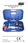
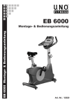
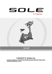
CR800
Recumbent
CU800
Upright
OWNER’S MANUAL
Please carefully read this entire manual before operating your new Bike.
Table of Contents
Important Safety Instructions…………………………………………………………………
2
Important Operation Instructions……………………………………………………………..
3
Recumbent Assembly Instructions………………………………………………………….
4
Upright Assembly Instructions……………………………………………………………….
11
Features………………………………………………………………………………………..
17
Operation of Your New Bike…………………………………………………………….……
18
Maintenance……………………………………………………………………………………
32
Recumbent Exploded View Diagram……………………………………………………….
33
Recumbent Parts List…..………..……………………………………………………………
34
Upright Parts List………..………..……………………………………………………………
37
Upright Exploded Diagram..…………………………………………………………………..
38
Thank you for purchasing our product, please save these instructions.
Please do not perform or attempt any customizing, adjustments, repair
or maintenance that is not described in this manual.
XR898 / XU878-AB05GS_1410E
1
Important Safety Instructions
WARNING - Read all instructions before assembling, using or servicing this appliance.
■ Before beginning this or any exercise program, consult a physician. This is especially important
for persons over the age of 35 or persons with pre-existing health conditions.
■ If you experience nausea, dizziness or other abnormal symptoms while exercising, stop your
workout at once and consult a physician.
■ To avoid muscular pain and strain, begin each workout by warming up and end it by cooling
down (slow pedaling at low resistance). Don’t forget to stretch at the end of the workout.
■ Keep children away from the bike. There are obvious pinch points and other areas of
caution that can cause harm.
■ Keep hands away from all moving parts.
■ Never drop or insert any object into any openings.
■ Do not use outdoors.
■ Do not attempt to use your bike for any purpose other than for the purpose it is
intended.
■ The hand pulse sensors are not medical devices. Various factors, including the user’s
movement, may affect the accuracy of heart rate readings. The pulse sensors are intended
only as exercise aids in determining heart rate trends in general.
■ WARNING: Heart rate monitoring system may be inaccurate. Over exercise may result in injury
or death. If you feel faint stop exercising immediately.
■ Wear proper shoes. High heels, dress shoes, sandals or bare feet are not suitable
for use on your bike. Quality athletic shoes are recommended to avoid leg fatigue.
■ This appliance is not intended for use by persons (including children) with reduced physical,
sensory or mental capabilities, or lack of experience and knowledge, unless they have been
given supervision or instruction concerning use of the appliance by a person responsible for
their safety.
■ Children should be supervised to ensure that they do not play with the appliance.
■ Max. user’s weight.: 150 kg
SAVE THESE INSTRUCTIONS - THINK SAFETY!
2
Important Operation Instructions
●
●
•
•
•
•
•
•
•
•
•
Never operate the bike without reading and completely understanding the results of any
operational change you request from the computer.
Do not use excessive pressure on console control keys. They are precision set to properly
function with little finger pressure. Pushing harder is not going to make the unit go faster or
slower. If you feel the buttons are not functioning properly with normal pressure, contact your
dealer.
Do not attempt any servicing or adjustments other than those described in this manual. All
else must be left to trained service personnel familiar with electro-mechanical equipment and
authorized under the laws of the country in question to carry out maintenance and repair
work.
Hold the handlebar for support when getting on or off the bike.
Make sure there is at least one meter of clearance between the bike and any fixed object.
The safety level of this bike can only be ensured if you inspect all parts for signs of wear or
visible damage before each use. If a part is damaged, do not use the bike. Replace any
damaged parts immediately and keep the bike out of use until repair can be made.
NEVER expose this bike to rain or moisture. This product is NOT designed for use outdoors,
near a pool or spa, or in any other high humidity environment. The operational temperature
specification is +10 to +40 degrees C, and humidity is 95%, non-condensing (no water drops
forming on surfaces).
To avoid injury please observe all minimum and maximum seat adjustment settings.
Place the bike on a firm, level surface. Place the bike on a protective surface to avoid
damaging the floor beneath the equipment.
If the wattage reading on the console seems incorrect, see your local dealer for recalibration.
The workload of this bike provides a speed-dependent type of exercise.
3
Assembly Pack Check List For RECUMBENT
Step 1
#77 - 3/8"x19
Flat Washer (6pcs)
#84 - 3/8" x 25
Flat Washer (4pcs)
#89 - 3/8"
Nylon Nut (6pcs)
#71 - 3/8” x 2”
Hex Head Bolt (4pcs)
#65 - 3/8” x 2-1/4”
Hex Head Bolt (4pcs)
#175 - 3/8” x 2-3/4”
Hex Head Bolt (2pcs)
Step 2
#176 - 3/8” x 3/4”
Hex Head Bolt (6pcs)
#136 - M5 x 15mm
Phillips Head Screw (4pcs)
4
#77 - 3/8"x19
Flat Washer (6pcs)
Step 3
#68 - 5/16” x 5/8”
Hex Head Bolt (8pcs)
#83 - 5/16" x 19
Curved Washer (2pcs)
#76 - 5/16" x 18
Flat Washer (6pcs)
#82 - 5/16”
Split Washer (2pcs)
Step 4
#105 - 4 x 16mm
Self Tapping Screw (4pcs)
#99 - M5 x 12mm
Phillips Head Screw (8pcs)
5
#186 - M6 x 18mm
Phillips Head Screw (4pcs)
Tools
#114 - Phillips Screw Driver (1 pc)
#112 - 12/14mm Wrench (1 pc)
6
#132 - 14/15mm Wrench (1 pc)
Assembly Instructions For RECUMBENT
STEP 1: REAR STABILIZER & SEAT HANDLEBAR ASSEMBLY
1. Install the Rear Stabilizer (7) onto the Main Frame with four 3/8” x 2-1/4” Hex Head bolts (65) and
four 3/8” x 25 Flat Washers (84).
2. Install the handlebar assembly (6) onto the seat carriage (4) with four 3/8” X 2” bolts (71) installed
through the top holes and secured with four 3/8” flat washers (77) and 3/8” nylon nuts (89). Install
two 3/8” X 2-3/4” bolts (175) through the side holes and secure with two 3/8” flat washers (77)
and 3/8” nylon nuts (89).
3. Plug the Left hand pulse wire (27) into the corresponding left socket (42) located in the left plastic
side case under the seat carriage, and the Right hand pulse wire (21) into the right socket (26).
7
STEP 2: SEAT BACK
1. Install Seat Back Frame (5) onto the Seat Carriage (4) with six 3/8” x 3/4” Hex Head bolts (176)
and 3/8”x 19 flat washers (77).
2. Install the Seat Back Cover (128) onto the Seat Back with four M5 × 15m/m Phillips Head Screws
(136).
8
STEP 3: CONSOLE MAST ASSEMBLY
1. Install the console mast cover (31) onto the console mast (2), making sure it is facing the correct
direction as in the picture below. Run the two wire harnesses through the bottom of the console
mast tube and out the top opening.
2. Slide the console mast into the receiving tube (1) being careful to not pinch the wires. Fasten the
console mast with six 5/16” x 5/8” bolts (68) and four 5/16” flat washers (76) on the side bolts and
two 5/16” curved washers (83) on the front bolts. Snap the console mast cover in place.
3. Install the front handlebars (3) onto the console mast with two 5/16” x 5/8” bolts (68), 5/16” split
washers (82) and 5/16” flat washers (76).
9
STEP 4: CONSOLE, SEAT, COVERS, PEDALS
1. Install the front and rear stabilizer covers (32 & 37) and secure to the frame with four M5 x 12mm
screws (99).
2. Install the left and right cup holders (39 & 38) to the rear handlebars with four self tapping screws
(105).
3. Install the bottom seat cushion (61) to the seat carriage (4) with four M6 x 18mm screws (186).
4. Install the Pedals (116 L, 117 R) into the Crank arms (51L, 51R). Remember that the left pedal
has a reverse thread and will be screwed into the crank in the opposite rotation from normal
threads. There is an “L” stamped into the end of the threaded post of the left pedal and an “R” in
the right. Make sure to tighten the pedals as much as you possibly can. It may be necessary to
re-tighten the pedals if you feel a thumping during pedaling the bike. A clicking noise, or thumping,
sound during pedaling is usually caused by the pedals being too loose.
5. Connect the two wire harnesses (44 & 45) to the corresponding connectors on the back of the
console. Install the console onto the console mast and secure with four M5 x 12mm screws (99)
being careful to not pinch the wires.
10
Assembly Pack Check List For UPRIGHT
Step 1
#50 - 3/8” x 2-1/4”
Hex Head Bolt (4pcs)
#71 - 3/8" x 25
Flat Washer (4pcs)
Step 2
#51 - 5/16” x 5/8”
Hex Head Bolt (7pcs)
#99 - 5/16"x19
Curved Washer (1pcs)
#72 - 5/16"x18
Flat Washer (6pcs)
Step 3
#51 - 5/16” x 5/8”
Hex Head Bolt (2pcs)
#103 - 5/16”
Split Washer (2pcs)
Step 4
#58 - M5 x 12mm
Phillips Head Screw (10pcs)
11
#72 - 5/16"x18
Flat Washer (2pcs)
Tools
#93 - Phillips Screw Driver (1pc)
#100 - 12/14mm Wrench (1pc)
12
#117. 13/15mm Wrench (1pc)
Assembly Instructions For UPRIGHT
STEP 1: REAR STABILIZER ASSEMBLY
1. Install the Rear Stabilizer (5) onto the Main Frame (1) with the four 3/8” x 2-1/4” Hex Head Bolts
(50) and four 3/8” x 25 Flat Washers (71).
13
STEP 2: FRONT CONSOLE MAST ASSEMBLY
1. Unravel the Computer Cable (29) and snake it through the Console Mast Cover (38) and the
Console Mast (2) until the cable connector comes out the top opening of the console mast. Slide
the plastic cover (38) onto the console mast, ensuring the correct orientation of the cover.
2. Install the Console Mast (2) onto the Main Frame (1) with seven 5/16” x 5/8” Hex Head bolts (51),
six 5/16” x 18 Flat Washers (72) on the side screws and one 5/16” x 19 Curved Washer (99) on
the front screw.
14
STEP 3: HANDLE BAR ASSEMBLY
1. Run the two hand pulse wires (26) into the hole in the handle bar mounting plate and out
through the hole in the console plate. Install the Handle Bar (3) onto the Console Mast (2) with
two 5/16” x 5/8” Hex Head bolts (51), two 5/16” x 18 Flat Washers (72) and two 5/16” Split
Washers (103) being careful not to pinch the hand pulse wires.
15
STEP 4: CONSOLE, SEAT, PEDALS AND BEAUTY COVERS ASSEMBLY
1. Insert the Computer Cable (29) and two Hand pulse cables (26) into the connectors in the back
of the Console (34). Install the Console (34) onto the Console Mast (2) with four M5x12mm
Phillips Head Screws (58).
2. Install the Front Stabilizer Cover (40) and the Rear Stabilizer Cover (41) onto the Main Frame (1)
with four M5x12mm Phillips Head Screws (58).
3. Install the Pedals (45 L, 46R) onto the Crank arms (16L, 16R). Remember that the left pedal has
a reverse thread and will be screwed into the crank in the opposite rotation from normal threads.
There is an “L” stamped into the end of the threaded post of the left pedal and an “R” in the right.
Make sure to tighten the pedals as much as you possibly can. It may be necessary to re-tighten
the pedals if you feel a thumping during pedaling the bike. A noise or feeling such as a thumping
or clicking is usually caused by the pedals being too loose.
4. Install the Seat mount slide (7) onto the track on top of the seat tube with the seat post facing
forward. Install the seat (19) onto the seat post.
5. Install the Drink Bottle Holder (116) onto the Console Mast (2) with two M5x12mm Phillips Head
Screws (58).
16
Features
Foot pedals
Through research performed with a leading sports scientist and physical rehabilitation expert, the
engineering has developed a breakthrough in pedal design. Typical stationary exercise
bikes are wider than a normal road bike. The reason is to allow for the braking mechanism,
pulleys, drive components and beauty covers. Since the bike is wider, so is the distance
between the pedals; this width between the pedals is called the Q factor.
It has designed our pedal system so the Q factor is the smallest in the industry, but we did not stop
there. We have also custom designed and tooled a new pedal that provides a two degree inward tilt
to compensate for the Q factor not being perfect. Having a small Q factor in addition to the two
degree inward tilt of the pedals puts the user into a biomechanical neutral alignment. This means
that your feet, ankles, knees and hips are lined up properly ensuring a comfortable workout.
Transportation
The bike is equipped with two transport wheels, which are engaged when rear of the bike is lifted.
17
Operation of Your Stationary Bike
■ RECUMBENT & UPRIGHT Console
FAN
DOT MATRIX
DISPLAY KEY
Resistance level, Program
Profiles and Lap Track
Switches Display information
PROGRAM KEY
HEART RATE
BARGRAPH
MESSAGE WINDOW
CONTROL KEYS
Time, Distance, Pulse,
Calories, RPM, KPH, Work
Level, Watts, METS
FAN ON/OFF
DISPLAY KEY
Switches Display information
Power on
The commercial bikes have a built-in generator for power and do not need to be plugged into an AC
outlet. To power up the Bike simply start to pedal, the console will turn on automatically. If the
console does not light when you pedal, check that the power switch is set to 0 (Generator). The
switch is located on the front, lower left side of the main plastic cover. There is an optional 24VAC
power transformer that is available through your dealer. The AC power transformer would be used if
the bike will be operated at very low speeds. In this scenario the power to the electronic console will
be too low to maintain the display. To use the AC power transformer plug it into an AC outlet and the
power input module of the bike and set the power switch to 1 (24VAC power input).
When initially powered on the console will perform an internal self-test. During this time all the lights
will turn on for a short time. When the lights go off the dot matrix display will show a software
version (i.e. VER 1.0) and the message window will display an odometer reading. The odometer
reading displays how many hours the bike has been used and how many virtual miles the bike has
gone. The display shows: ODO 123 MI 123 HRS.
The odometer will remain displayed for only a few seconds then the console will go to the start up
display. The dot matrix display will be scrolling through the different profiles, showing the programs,
and the message window will be scrolling the start up message. You may now begin to use the
console.
18
Console Operation
Quick Start
This is the quickest way to start a workout. After the console powers up you just press the Start key
to begin. This will initiate the Quick Start mode. In Quick Start the Time will count up from zero, all
workout data will start to accrue and the workload may be adjusted manually by pressing the Up
and Down buttons. The dot matrix display will show a ¼ mile(0.4KM)track display or just the bottom
row lit at first, depending on how the display button has been set (see Basic information below). As
you increase the workload more rows will light indicating a harder workout. The bike will get harder
to pedal as the rows increase. The dot matrix has 24 columns of lights and each column represents
1 minute. At the end of the 24th column (or 24 minutes of work) the display will wrap around and
start at the first column again.
There are 40 levels of resistance – displayed as 10 rows of lights - available for plenty of variety.
The first 10 levels are very easy workloads, and the changes between levels are set to a good
progression for de-conditioned users. Levels 10-20 are more challenging but the increases from
one level to the next remain small. Levels 20-30 start getting tough as the levels jump more
dramatically. Levels 30-40 are extremely hard and are good for short interval peaks and elite athletic
training.
Basic information
The Dot Matrix, or Profile Window, has two display modes. When you begin a program the dot
matrix will display the workout Profile. To the left of the dot matrix there is a button labeled Display.
Pressing this button once will switch the display to show a quarter mile track. If the Display button is
pressed again the dot matrix will switch back and forth between Track and Profile mode every few
seconds. To turn off the scan mode press the Display key again. This will return you to the profile
display mode.
The Message Window will initially be displaying Time and Distance information. On the bottom left
of the message window is a button labeled Display. Each time this Display button is pressed the
next set of information will appear, four windows in all. In order: Time and Distance, Pulse and Kcal
(Calories), Speed in RPM and MPH, Work Level and Watts, then METs. If the Display button is
pressed during the METs display the Scan light will come on and the message window will show
each set of data for four seconds then switch to the next set of data in a continuous loop. Pressing
the Display button again will bring you back to the beginning.
Below the Dot matrix display is a Heart Icon and a Bar Graph. The Bike has a built in heart rate
monitoring system. Simply grasping the hand pulse sensors, or wearing a heart rate chest belt
transmitter, will start the Heart Icon blinking (this may take a few seconds). The Message Window
will display your heart rate, or Pulse, in beats per minute. The Bar Graph represents the percentage
of your maximum heart rate you are currently achieving. NOTE: You must enter your age during
program setup for the Bar Graph to be accurate. Refer to Heart Rate section for details about these
features and how they can help you work out more efficiently.
The Stop/Reset button actually has several functions. Pressing the Stop/Reset key once during a
program will Pause the program for 5 minutes (when you stop pedaling without AC power the
display will turn off but the memory will be saved for 5 minutes just like the pause mode). If you
19
need to get a drink, answer the phone, or any of the many things that could interrupt your workout,
this is a great feature. To resume your workout during Pause just press the Start key or start
pedaling. If the Stop/Reset button is pressed twice during a workout the program will end and the
console will return to the start up screen. If the Stop/Reset key is held down for 3 seconds the
console will perform a complete Reset. During data entry for a program the Stop/Reset key
performs a Previous Screen function. This allows you to go back one step in the programming
each time you press the Stop/Reset key.
The Program Keys are used to preview each program. When you first turn the console on you may
press each program key to preview what the program profile looks like. If you decide that you want
to try a program, press the corresponding program key and then press the Enter key to select the
program and enter into the data-setup mode.
The program keys also act as a Number Key Pad when you are in the data-setup mode. Under
each program key is a number. If you are setting new data such as Age, weight etc., you can use
these keys to enter the numbers quickly.
The console includes a built-in fan to help keep you cool. To turn the fan on press the key on the
right side, front of the console
Programming the console
Each of the programs can be customized with your personal information and changed to suit your
needs. Some of the information asked for is necessary to ensure the readouts are correct. You will
be asked for your Age and Weight. Entering your Age ensures that the Heart Rate bar graph
shows the correct number. Your Age is also necessary during the Heart Rate control program to
ensure the correct settings are in the program for your Age. Otherwise the work settings could be
too high or low for you; entering your Weight aides in calculating a more correct Calorie reading.
Although we cannot provide an exact calorie count we do want to be as close as possible.
Entering/Changing Settings
When you enter a program (by pressing a program key, then enter key) you have the option of
entering your own personal settings. If you want to workout without entering new settings then just
press the Start key. This will bypass the programming of data and take you directly to the start of
your workout. If you want to change the personal settings then just follow the instructions in the
message window. If you start a program without changing the settings the default - or pre-saved –
settings will be used.
20
Manual
The Manual program works as the name implies, manually. This means that you control the
workload yourself and not the computer. To start the Manual program follow the instructions below
or just press the Manual button then the Enter button and follow the directions in the message
window.
1. Press the Manual key then press the Enter key.
2. The message window will ask you to enter your Age. You may enter your Age, using the Up
and Down keys or the numeric key pad, then press the Enter key to accept the new number
and proceed on to the next screen.
3. You are now asked to enter your Weight. You may adjust the Weight number using the Up
and Down keys, or the numeric key pad, then press enter to continue.
4. The next setting is Time. You may adjust the Time and press enter to continue.
5. Now you are finished editing the settings and can begin your workout by pressing the Start
key. You can also go back and modify your settings by pressing the Enter key. NOTE: At any
time during the editing of Data you can press the Stop key to go back one level, or screen.
6. The program automatically starts you at level one. This is the easiest level and it is a good
idea to stay at level one for a while to warm up. If you want to increase the work load at any
time press the Up key; the Down key will decrease the workload.
7. During the Manual program you will be able to scroll through the data in the message window
by pressing the adjacent Display key. You may also switch between the profile display and a
quarter mile track by pressing the Display key adjacent to the dot matrix display.
8. When the program ends you may press Start to begin the same program again or Stop to exit
the program, or you can save the program you just completed as a custom program by
pressing the Custom key and following the instructions in the message window.
Preset Programs
The bike has five different programs that have been designed for a variety of workout goals. These
five programs have factory preset profiles for achieving these different goals. The initial built-in level
of difficulty for each program is set to a relatively easy level. You may adjust the level of difficulty
(Max level) for each program before beginning by following the instructions in the message window
after selecting your program.
HILL
The Hill program simulates going up and down a hill. The resistance in the pedals will steadily
increase and then decrease during the program.
Work Profile
21
FATBURN
The Fat Burn program is designed, as the name implies, to maximize the burning of fat. There are
many schools of thought on the best way to burn fat but most experts agree that a lower exertion
level that stays at a steady workload is the best. The absolute best way to burn fat is to keep your
heart rate at around 60% to 70% of its maximum potential. This program does not use heart rate but
simulates a lower, steady exertion workout.
Work Profile
Cardio
The Cardio program is designed to increase your Cardio vascular function. This is exercise for your
heart and lungs. It will build up your heart muscle and increase blood flow and lung capacity. This is
achieved by incorporating a higher level of exertion with slight fluctuations in work.
Work Profile
Strength
The Strength program is designed to increase muscular strength in your lower body. This program
will steadily increase in resistance to a high level and then keeps you there. This is designed to
strengthen and tone your legs and glutes.
Work Profile
22
Interval
The Interval program takes you through high levels of intensity followed by periods of low intensity.
This program increases your endurance by depleting your oxygen level followed by periods of
recovery to replenish oxygen. Your cardio vascular system gets programmed to use oxygen more
efficiently this way.
Work Profile
Programming Preset Programs:
1. Select the desired program button then press the Enter key.
2. The message window will ask you to enter your Age. You may adjust the age setting, using the
Up and Down keys, then press the Enter key to accept the new number and proceed on to the
next screen.
3. You are now asked to enter your Weight. You may adjust the weight number using the Up and
Down keys, then press enter to continue.
4. Next is Time. You may adjust the Time and press enter to continue.
5. Now you are asked to adjust the Max Level. This is the peak exertion level you will experience
during the program (at the top of the hill). Adjust the level and then press enter.
6. Now you are finished editing the settings and can begin your workout by pressing the Start key.
You can also go back and modify your settings by pressing the Stop key to go back one level,
or screen.
7. If you want to increase or decrease the workload at any time during the program press the Up
or Down key. This will change the workload settings of the entire profile, although the profile
picture on the screen will not change. The reason for this is so that you can see the entire
profile at all times. If the profile picture is changed it will look distorted and not a true
representation of the actual profile. When you make a change to the workload, the message
window will show the current column, and program maximum, levels of work.
8. During the program you will be able to scroll through the data in the message window by
pressing the Display key next to the message window.
9. When the program ends the message window will show a summary of your workout. The
summary will be displayed for a short time then the console will return to the start-up display.
23
Custom User Defined Program
The custom program allows you to build and save a custom program. You can build your own
custom program by following the instructions below or you can save any other preset program you
complete as a custom program. The custom program allows you to further personalize it by adding
your facility name.
1. Press the Custom key. The message window will show a welcome message; if you had
previously saved a program the message will contain the name you gave it. Then press the
Enter key to begin programming.
2. When you press enter, the message window will show “Name – A”, if there is no name saved. If
the name “Custom Workout” had been previously saved the message window will show
“Name – Custom Workout” and the C in Custom will be blinking. If there is a name saved you
can change it or you may press the Stop key to keep the name and continue to the next step. If
you want to enter a name use the Up and/or the Down key to change the first letter then press
Enter to save the first letter and continue to the next letter. When you have finished entering the
name press the Stop key to save the name and continue to the next step.
3. The message window will ask you to enter your Age. You may enter your Age, using the Up
and Down keys or the numeric key pad, then press the Enter key to accept the new number
and proceed on to the next screen.
4. You are now asked to enter your Weight. You may adjust the Weight number using the Up and
Down keys or the numeric key pad then press enter to continue.
5. Next is Time. You may adjust the Time and press enter to continue.
6. Now you are asked to adjust the Max Level. This is the peak exertion level you will experience
during the program. Adjust the level and then press enter.
7. Now the first column will be blinking and you are asked to adjust the level for the first segment
of the workout. When you finish adjusting the first segment, or if you don’t want to change, then
press enter to continue to the next segment.
8. The next segment will show the same level as the previously adjusted segment. Repeat the
same process as the last segment then press enter. Continue this process until all twenty
segments have been set.
9. The message window will then tell you to press enter to save the program. After saving the
program the message window says “New program saved” then will give you the option to Start
or modify the program. Pressing Stop will exit to the start up screen.
10. If you want to increase or decrease the workload at any time during the program press the Up
or Down key. This will only affect the workload for the present position in the profile. When the
profile changes to the next column it will return to the preset work level.
11. During the User 1 or User 2 program you will be able to scroll through the data in the message
window by pressing the adjacent Display key, switch between the profile display and a quarter
mile track by pressing the Display key adjacent to the matrix, use the heart rate monitoring
features and can switch to heart rate Auto-Pilot mode. See Heart Rate section for details of
this feature).
24
Fit-Test
The fitness test is based on the YMCA protocol and is a sub-maximal test that uses pre-determined,
fixed work levels that are based on your heart rate readings as the test progresses. The test will
take anywhere between 6 to 15 minutes to complete, depending on your level of fitness. The test
ends when your heart rate reaches 85% of maximum at any time during the test or your heart rate is
between 110 bpm and 85% at the end of two consecutive stages. At the end of the test a VO2max
score will be given. VO2max stands for Volume of Oxygen uptake which is a measurement of how
much oxygen you need to perform a known amount of work.
The YMCA protocol uses two to four, 3 minute stages of continuous exercise (see charts below).
You will be asked to choose either, Male or Female at the beginning of the test. This choice
determines which test parameters will be used during the test as shown in the charts below. The
only caveats are that if you are a very de-conditioned Male you need to choose option Female. If
you are a very conditioned female you need to choose option Male.
Workload chart for male or very fit female:
Level 12 50 watts -
1st
Stage
300 kgm/min
HR
< 90
90 - 105
> 105
2nd
Stage
Level 29 150 watts -
Level 26 125 watts -
Level 23 100 watts -
900 kgm/min
750 kgm/min
600 kgm/min
HR
HR <120
HR 120-135
HR >135
HR <120
HR 120-135
HR >135
HR <120
HR 120-135
HR >135
3rd
stage
Level 36 225 watts -
Level 34 200 watts -
Level 32 175 watts -
Level 34 200 watts -
Level 32 175 watts -
Level 29 150 watts -
Level 32 175 watts -
Level 29 150 watts -
Level 26 125 watts -
1350 kgm/min
1200 kgm/min
1050 kgm/min
1200 kgm/min
1050 kgm/min
900 kgm/min
1050 kgm/min
900 kgm/min
750 kgm/min
Workload chart for female or de-conditioned male
Level 5 (25W)
150 kgm/min
HR: 90-100
HR>100
Heart Rate
HR<80
1st Stage
HR: 80-90
2nd Stage
Level 26 (125W) 750 kgm/min
Level 23 (100W)
600 kgm/min
Level 18 (75W)
450 kgm/min
Level 12 (50W)
300 kgm/min
3rd Stage
Level 29 (150W)
900 kgm/min
Level 26 (125W)
750 kgm/min
Level 23 (100W)
600 kgm/min
Level 18 (75W)
450 kgm/min
4th Stage (if needed)
Level 32 (175W)
1050 kgm/min
Level 29 (150W)
900 kgm/min
Level 25 (117W)
700 kgm/min
Level 23 (100W)
600 kgm/min
25
Fitness test programming:
1. Press the Fit-test button and press enter.
2. The message window will ask you to enter your Age. You may adjust the age setting, using
the Up and Down keys then press the Enter key to accept the new number and proceed on
to the next screen.
3. You are now asked to enter your Weight. You may adjust the weight number using the Up
and Down keys then press enter to continue.
4. Now press Start to begin the test.
Before the test:
•
•
•
•
•
Make sure you are in good health; check with your physician before performing any exercise if
you are over the age of 35 or persons with pre-existing health conditions.
Adjust the seat to the proper position so that when your leg is extended during pedaling there is
a slight bend at the knee of about 5 degrees.
Make sure you have warmed up and stretched before taking the test.
Do not take in caffeine before the test.
Hold the hand grips gently, do not tense up.
During the test:
•
•
•
The console must be receiving a steady heart rate for the test to begin. You may use the hand
pulse sensors or wear a heart rate chest strap transmitter.
You must maintain a steady 50 RPM pedal speed. If your pedal speed drops below 48 RPM or
goes above 52 RPM the console will emit a steady beeping sound until you are within this range.
You may scroll through the various data readings in the message window by pressing the
Display button under the message window.
1. The message window will always display your pedal speed on the right side to help you
maintain 50RPM.
2. The data shown during the test is:
a. Work in KGM is actually an abbreviated form of kg-m/min. which is a work
measurement of kilogram-force meter/minute
b. Work in Watts (1 watt is equal to 6.11829727787 kg-m/min.)
c. HR is your actual heart rate; TGT is the target heart rate to reach to end the test.
d. Time is the total elapsed time of the test.
After the test:
•
•
Cool down for about one to three minutes.
Take note of your score because the console will automatically return to the start-up mode after
a few minutes.
26
What your score means:
VO2max Chart for males and very fit females
18-25
26-35
36-45
46-55
56-65
65+
years
old
years
old
years
old
years
old
years
old
years
old
>60
>56
>51
>45
>41
>37
good
52-60
49-56
43-51
39-45
36-41
33-37
above
average
47-51
43-48
39-42
35-38
32-35
29-32
average
42-46
40-42
35-38
32-35
30-31
26-28
below
average
37-41
35-39
31-34
29-31
26-29
22-25
poor
30-36
30-34
26-30
25-28
22-25
20-21
<30
<30
<26
<25
<22
<20
excellent
very poor
VO2max Chart for females and de-conditioned males
excellent
18-25
26-35
36-45
46-55
56-65
65+
years
old
years
old
years
old
years
old
years
old
years
old
56
52
45
40
37
32
good
47-56
45-52
38-45
34-40
32-37
28-32
above
average
42-46
39-44
34-37
31-33
28-31
25-27
average
38-41
35-38
31-33
28-30
25-27
22-24
below
average
33-37
31-34
27-30
25-27
22-24
19-22
poor
28-32
26-30
22-26
20-24
18-21
17-18
<28
<26
<22
<20
<18
<17
very poor
27
Heart Rate Training
A word about Heart Rate:
The old motto, “no pain, no gain”, is a myth that has been overpowered by the benefits of exercising
comfortably. A great deal of this success has been promoted by the use of heart rate monitors. With the
proper use of a heart rate monitor, many people find that their usual choice of exercise intensity was
either too high or too low and exercise is much more enjoyable by maintaining their heart rate in the
desired benefit range.
To determine the benefit range in which you
wish to train, you must first determine your
Maximum Heart Rate. This can be
accomplished by using the following formula:
220 minus your age. This will give you the
Maximum heart rate (MHR) for someone of your
age. To determine the effective heart rate range
for specific goals you simply calculate a
percentage your MHR. Your Heart rate training
zone is 50% to 90% of your maximum heart rate.
60% of your MHR is the zone that burns fat
while 80% is for strengthening the cardio
vascular system. This 60% to 80% is the zone
to stay in for maximum benefit.
90
For someone who is 40 years old their target
heart rate zone is calculated:
220 – 40 = 180 (maximum heart rate)
180 x .6 = 108 beats per minute (60% of maximum)
180 X .8 = 144 beats per minute (80% of maximum)
So for a 40 year old the training zone would be 108 to 144 beats per minute.
If you enter your age during programming the console will perform this calculation automatically.
Entering your age is used for the Heart Rate control programs. After calculating your Maximum Heart
Rate you can decide upon which goal you would like to pursue.
The two most popular reasons for, or goals, of exercise are cardiovascular fitness (training for the heart
and lungs) and weight control. The black columns on the chart above represent the Maximum Heart
Rate for a person whose age is listed at the bottom of each column. The training heart rate, for either
cardiovascular fitness or weight loss, is represented by two different lines that cut diagonally through the
chart. A definition of the lines’ goal is in the bottom left-hand corner of the chart. If your goal is
cardiovascular fitness or if it is weight loss, it can be achieved by training at 80% or 60%, respectively, of
your Maximum Heart Rate on a schedule approved by your physician. Consult your physician before
participating in any exercise program.
With all Heart Rate Control bike machines you may use the heart rate monitor feature without using the
Heart Rate Control program. This function can be used during manual mode or during any of the nine
different programs. The Heart Rate Control program automatically controls resistance at the pedals.
”WARNING” Heart rate monitoring system may be inaccurate. Over exercise may result in injury or
death. If you feel faint stop exercising immediately.
28
Rate of Perceived Exertion
Heart rate is important but listening to your body also has a lot of advantages. There are more
variables involved in how hard you should workout than just heart rate. Your stress level, physical
health, emotional health, temperature, humidity, the time of day, the last time you ate and what you
ate, all contribute to the intensity at which you should workout. If you listen to your body, it will tell
you all of these things.
The rate of perceived exertion (RPE), also know as the Borg scale, was developed by Swedish
physiologist G.A.V. Borg. This scale rates exercise intensity from 6 to 20 depending upon how you
feel or the perception of your effort.
The scale is as follows:
Rating Perception of Effort
6 Minimal
7 Very, very light
8 Very, very light +
9 Very light
10 Very light +
11 Fairly light
12 Comfortable
13 Somewhat hard
14 Somewhat hard +
15 Hard
16 Hard +
17 Very hard
18 Very hard +
19 Very, very hard
20 Maximal
You can get an approximate heart rate level for each rating by simply adding a zero to each rating.
For example a rating of 12 will result in an approximate heart rate of 120 beats per minute. Your
RPE will vary depending up the factors discussed earlier. That is the major benefit of this type of
training. If your body is strong and rested, you will feel strong and your pace will feel easier. When
your body is in this condition, you are able to train harder and the RPE will support this. If you are
feeling tired and sluggish, it is because your body needs a break. In this condition, your pace will
feel harder. Again, this will show up in your RPE and you will train at the proper level for that day.
29
Using a Heart Rate Transmitter
How to wear your wireless chest strap transmitter:
1. Attach the transmitter to the elastic strap using the locking parts.
2. Adjust the strap as tightly as possible as long as the strap is not too tight to remain comfortable.
3. Position the transmitter with the logo centered in the middle of your body facing away from your
chest (some people must position the transmitter slightly left of center). Attach the final end of the
elastic strap by inserting the round end and, using the locking parts, secure the transmitter and
strap around your chest.
4. Position the transmitter immediately below the pectoral muscles.
5. Sweat is the best conductor to measure very minute heart beat electrical signals. However, plain
water can also be used to pre-wet the electrodes (2 black square areas on the reverse side of the
belt and either side of transmitter). It’s also recommended that you wear the transmitter strap a
few minutes before your work out. Some users, because of body chemistry, have a more difficult
time in achieving a strong, steady signal at the beginning. After “warming up”, this problem
lessens. As noted, wearing clothing over the transmitter/strap doesn’t affect performance.
6. Your workout must be within range - distance between transmitter/receiver – to achieve a strong
steady signal. The length of range may vary somewhat but generally stay close enough to the
console to maintain good, strong, reliable readings. Wearing the transmitter immediately against
bare skin assures you of proper operation. If you wish, you may wear the transmitter over a shirt.
To do so, moisten the areas of the shirt that the electrodes will rest upon.
Note: The transmitter is automatically activated when it detects activity from the user’s heart. Additionally, it
automatically deactivates when it does not receive any activity. Although the transmitter is water resistant, moisture
can have the effect of creating false signals, so you should take precautions to completely dry the transmitter after
use to prolong battery life (estimated transmitter battery life is 2500 hours). If your chest strap has a replaceable
battery the replacement battery is Panasonic CR2032.
Erratic Operation:
Caution! Do not use this bike for Heart Rate Control unless a steady, solid Actual Heart Rate
value is being displayed. High, wild, random numbers being displayed indicate a problem.
Areas to look at for interference, which may cause erratic heart rate:
(1) Microwave ovens, TVs, small appliances, etc.
(2) Fluorescent lights.
(3) Some household security systems.
(4) Perimeter fence for a pet.
(5) Some people have problems with the transmitter picking up a signal from their skin. If you have
problems try wearing the transmitter upside down. Normally the transmitter will be oriented so
the logo is right side up.
(6) The antenna that picks up your heart rate is very sensitive. If there is an outside noise source,
turning the whole machine 90 degrees may de-tune the interference.
(7) If you continue to experience problems contact your dealer.
30
Heart Rate Control (HR) Program operation
To start the HR program follow the instructions below or just press the HR key then the Enter button
and follow the directions in the message window.
1. Press the HR key then press the Enter key.
2. The message window will ask you to enter your Age. You may enter your Age, using the Up
and Down keys or the numeric key pad, then press the Enter key to accept the new number
and proceed on to the next screen.
3. You are now asked to enter your Weight. You may adjust the Weight number using the Up and
Down keys or the numeric key pad, then press enter to continue.
4. Next is Time. You may adjust the Time and press enter to continue.
5. Now you are asked to adjust the Heart rate Level. This is the heart rate level you will
experience during the program. Adjust the level and then press enter.
6. Now you are finished editing the settings and can begin your workout by pressing the Start key.
You can also go back and modify your settings by pressing the Enter key. NOTE: At any time
during the editing of Data you can press the Stop key to go back one level, or screen.
7. If you want to increase or decrease the workload at any time during the program press the Up
or Down key. This will allow you to change your target heart rate at any time during the
program.
8. During the HR program you will be able to scroll through the data in the message window by
pressing the adjacent Display key.
9. When the program ends you may press Start to begin the same program again or Stop to exit
the program or you can save the program you just completed as a custom user program by
pressing a User key and following the instructions in the message window.
Watts Program operation (Not to be used for medical purposes)
Watts program is a controllable constant power that is adjustable LEVEL when you speed is
changed. To start the Watts program follow the instructions below or just press the Watts key then
the Enter button and follow the directions in the message window.
1. Press the Watts key then press the Enter key.
2. The message window will ask you to enter your Age. You may enter your Age, using the Up
and Down keys or the numeric key pad, then press the Enter key to accept the new number
and proceed on to the next screen.
3. You are now asked to enter your Weight. You may adjust the Weight number using the Up and
Down keys or the numeric key pad, then press enter to continue.
4. Next is Time. You may adjust the Time and press enter to continue.
5. Now you are asked to adjust the Target Watts. This is the constant power you will experience
during the program. Adjust the up/down and then press enter.
6. Now you are finished editing the settings and can begin your workout by pressing the Start key.
You can also go back and modify your settings by pressing the Enter key. NOTE: At any time
during the editing of Data you can press the Stop key to go back one level, or screen.
7. If you want to increase or decrease the workload at any time during the program press the Up
or Down key. This will allow you to change your target Watts at any time during the program.
8. During the Watts program you will be able to scroll through the data in the message window by
pressing the adjacent Display key.
When the program ends you may press Start to begin the same program again or Stop to exit the
program and following the instructions in the message window.
31
Maintenance:
1. Wipe down all areas in the sweat path with a damp cloth after each workout.
2. If a squeak, thump, clicking or rough feeling develops the main cause is most likely one of two
reasons:
1) The hardware was not sufficiently tightened during assembly. All bolts that were
installed during assembly need to be tightened as much as possible. It may be
necessary to use a larger wrench than the one provided if you cannot tighten the bolts
sufficiently. I cannot stress this point enough; 90% of calls to the service department for
noise issues can be traced to loose hardware.
2) The crank arm nut and/or the pedals need to be retightened.
3. If squeaks or other noises persist, check that the unit is properly leveled. There are 2 leveling
pads on the bottom of the rear stabilizer, use a 14mm wrench (or adjustable wrench) to adjust
the levelers.
Maintenance Menu in console software:
The console has built in maintenance/diagnostic software. The software will allow you to change the
console settings from English to Metric and turn off the beeping of the speaker when a key is
pressed for example. To enter the Maintenance menu (may be called Engineering mode, depending
on version) press and hold down the Start, Stop and Enter keys. Keep holding the keys down for
about 5 seconds and the message window will display “ALTXXXX Engineering mode”. Press the
enter button to access the menu below:
a. Key test (will allow you to test all the keys to make sure they are functioning)
b. Display test (tests all the display functions)
c. Functions (Press enter to access settings)
i. Sleep mode (Turn on to have the console power down automatically after
20 minutes of inactivity)
ii. Pause Mode (Turn on allow 5 minutes of pause, turn off to have the console
pause indefinitely)
iii. ODO reset (reset the odometer)
iv. Units (Set to English or Metric display readings)
v. Beep (Turn on or off the beep when a key is pressed)
vi. D/A test (tests the brake resistance)
vii. Exit
d. Security (Allows you to lock the keypad so no unauthorized use is allowed)
e. Factory settings (Access only allowed by manufacturing)
32
Recumbent Exploded View Diagram
33
Recumbent Parts List
Dwg #
1
2
3
4
5
6
7
8
9L
9R
10
11
12
13
14
15
16
17
18
19
20
21
22
23
24
25
26
27
28
29
30
31
32
33
34
35
36
37
38
39
42
43
44
45
46
Part description
Main Frame
Console Mast
Mast Handle bar Assembly
Seat Carriage
Seat Back Frame
Seat Handle Bar
Rear Stabilizer
Crank Axle
Seat Wheel Adjustment Plate L
Seat Wheel Adjustment Plate R
Idler Wheel Assembly
Seat Stop Axle
Seat Position Latch
Backing Plate
Aluminum Axle
Rack
Spacer for Stopper Axle
Rubber Foot
Transportation Wheel
Console Assembly
Drive Pulley
950m/m_Handpulse W/Cable Assembly(R)
Rubber Foot Pad
Ø32 (3.0T)_Button Head Plug
Ø25.4 (3.0T)_Button Head Plug
Seat Track Wheel
300m/m_Handpulse Wire, Coiled
750m/m_Handpulse W/Cable Assembly(L)
Crank Arm End Cap
Front Shroud (L)
Front Shroud (R)
Console Mast Cover
Front Stabilizer Cover
Step Cover
Round Disk
Rear Shroud (L)
Rear Shroud (R)
Rear Stabilizer Cover
Drink Bottle Holder (R)
Drink Bottle Holder (L)
300m/m_Hand Pulse Sensor Assembly W/Cable
Generator/Brake Controller
Computer Cable
2100m/m_Hand Pulse Sensor Assembly W/Cable
400m/m_Hall Sencor
()
()
34
Qty
1
1
1
1
1
1
1
1
2
2
1
2
1
3
1
1
4
2
2
1
1
1
2
2
2
8
1
1
2
1
1
1
1
1
2
1
1
1
1
1
1
1
1
1
1
Dwg #
47
48
51L
51R
52
53
54
55
56
61
63
64
65
66
68
71
72
73
75
76
77
78
79
80
82
83
84
85
86
87
88
89
90
91
93
94
95
97
98
99
101
102
103
104
105
106
107
108
109
Part description
750m/m_Wire Brake Coil Harness
1100m/m_Generator Wire Harness
Crank Arm (L)
Crank Arm (R)
6004_Bearing
6203_Bearing
Drive Belt
Generator/Brake
Magnet
Seat
Seat Back
Handgrip Foam
3/8" × 2- 1/4"_Hex Head Bolt
1/4" × 3/4"_Hex Head Bolt
5/16" × 5/8"_Hex Head Bolt
3/8" × 2"_Hex Head Bolt
1/4" × 13 × 1T_Flat Washer
1/4" × 19 × 1.5T_Flat Washer
Ø17 × 23.5 × 1T_Flat Washer
5/16" × 18 × 1.5T_Flat Washer
3/8" × 19 × 1.5T_Flat Washer
3/16" × 15 × 1.5T_Flat Washer
Ø8 × Ø18 × 3T_Knurled Lock Washer
Ø1/4"_Split Washer
5/16" × 1.5T_Split Washer
5/16" × 19 × 1.5T_Curved Washer
3/8" × 25 × 2.0T_Flat Washer
Ø17_C Ring
Ø20_C Ring
M8 × 170m/m_ J Bolt
M8 × 7T _Nyloc Nut
3/8" × 7T_Nyloc Nut
1/4" × 8T_Nyloc Nut
5/16" × 6T_Nyloc Nut
M6 × 38m/m_Socket Head Cap Bolt
5/16" × 3/4"_Hex Head Bolt
M5 × 12m/m_Flat Head Socket Screw
Ø3 × 20m/m_Tapping Screw
M6 × 15m/m_Phillips Head Screw
M5 × 12m/m_Phillips Head Screw
5 × 16m/m_Tapping Screw
5 × 19m/m_Tapping Screw
Ø3.5 × 16m/m_Sheet Metal Screw
Spring
Ø4 × 16 m/m_Sheet Metal Screw
5/16" × 1- 3/4"_Button Head Socket Bolt
Ø3.5 × 20m/m_Sheet Metal Screw
M10 × 1.25_Nut
3/8" × 7T_Nut
35
Qty
1
1
1
1
2
2
1
1
1
1
1
2
4
8
8
4
16
4
1
7
14
3
4
7
8
2
4
1
2
1
5
6
4
2
1
6
10
4
7
12
8
4
14
1
4
2
3
2
4
Dwg #
110
111
112
114
116
117
124
125
126
127
128
129
132
136
140
141
143
148
160
161
162
163
164
165
166
167
168
169
170
171
172
173
174
175
176
177
178
179
180
185
186
Part description
3/8" × 2"_Flat Head Socket Bolt
M5 × 10.Ø14 × 2T_Thumb Head Socket Screw
12.14m/m _Wrench
Phillips Head Screw Driver
Pedal (L)
Pedal (R)
Rod End Sleeve
Seat Carriage Cover
HGP Wire Grommet
5/16" × 16 × 1T_Flat Washer
Seat Back Cover
M6_Nyloc Nut
14.15m/m _Wrench
M5 × 15m/m_Phillips Head Screw
Hall Sensor Rack
Handle Bar Cover
Seat Track Fixing Plate
Block
5/16" × 16 × 1.5T_Flat Washer
M6 × 10L_Flat Phillips Head Screw
1/4" × 16 × 1.0T_Flat Washer
Sleeve
M6 × 19L_Nut
M6 × 10L_Button Head Socket Bolt
PU Wheel
Seat Front/Aft Adjustment Lever
Lever Anchor
M5 × 25m/m_Flat Head Socket Screw
Ø15 × Ø6 × 4T_Nylon Washer
M5 × 45m/m_Socket Head Cap Bolt
Ø3/16" × 10 × 1T _Flat Washer
M5 × 5T_Nyloc Nut
Ø3 × 12m/m__Sheet Metal Screw
3/8" × 2- 3/4"_Hex Head Bolt
3/8" × 3/4"_Hex Head Bolt
Rubber Foot Pad
Square End Cap
M8 × 15m/m_Button Head Socket Bolt
M5 × 30m/m_Phillips Head Screw
3/8" × 4T_Nut
M6 × 18m/m_Phillips Head Screw
36
Qty
2
8
1
1
1
1
1
1
1
3
1
1
1
4
1
1
1
1
6
4
4
4
4
4
4
1
1
2
1
1
1
1
2
2
6
1
1
4
4
1
4
Upright Exploded View Diagram
37
Upright Parts List
Dwg #
1
2
3
5
6
7
8
9
11
12
13
14
15
16L
16R
17
18
19
20
21
22
23
24
25
26
28
29
30
31
34
35
36
37
38
39
40
41
42
43
44
45
46
47
49
50
Part description
Main Frame
Console Mast
Seat Handle Bar
Rear Stabilizer
Seat Slider
Sliding Seat Mount
Fix Plate
Idler Wheel Assembly
Crank Axle
Fixing Plate
Chain Cover Bracket
Drive Belt
Drive Pulley
Crank Arm (L)
Crank Arm (R)
6004_Bearing
6203_Bearing
Seat
Induction Brake
Generator/Brake Controller
Magnet
Hall Sencor
1" × 255L × 5T_Handgrip Foam
1" × 205L × 5T_Handgrip Foam
800m/m_Handpulse W/Cable Assembly(white)
800m/m_Handpulse W/Cable Assembly(red)
2000m/m_Computer Cable
200m/m_Wire Brake Coil Harness
Generator Wire Harness
Console Assembly
Rubber Foot
Chain Cover (L)
Chain Cover (R)
Console Mast Cover
Seat Post Cover
Front Stabilizer Cover
Rear Stabilizer Cover
Handgrip Side Cap (Top)
Handgrip Side Cap (Bottom)
Hall Sensor Rack
Pedal (L)
Pedal (R)
Transportation Wheel
Ø25.4 × 2.0T__Button Head Plug
3/8" × 2-1/4"_Hex Head Bolt
38
Qty
1
1
1
1
1
1
1
1
1
1
1
1
1
1
1
2
2
1
1
1
1
1
2
2
1
1
1
1
1
1
4
1
1
1
1
1
1
2
2
1
1
1
2
4
4
Dwg #
51
52
53
54
55
56
58
59
61
62
63
65
66
67
68
69
70
71
72
73
76
77
78
79
80
82
83
85
86
93
96
97
99
100
102
103
105
106
107
114
115
116
117
118
Part description
5/16" × 5/8"_Hex Head Bolt
5 × 19m/m_Tapping Screw
5/16" × 1-3/4"_Button Head Socket Bolt
1/4" × 3/4"_Hex Head Bolt
M8 × 170m/m_J Bolt
M6 × 15m/m_Phillips Head Screw
M5 × 12m/m_Phillips Head Screw
3/8" × 2m/m_Flat Head Socket Bolt
5 × 16m/m_Tapping Screw
Ø3 × 20m/m_Tapping Screw
Ø3.5 × 16m/m_Sheet Metal Screw
Ø3 × 10m/m_Tapping Screw
Ø17_C Ring
Ø20_C Ring
4 × 12m/m_Sheet Metal Screw
1/4" × 13 × 1T_Flat Washer
3/8" × 19 × 1.5T_Flat Washer
3/8" × 25mm × 2.0T_Flat Washer
5/16" × 18mm × 1.5T_Flat Washer
Ø17 × 23.5 × 1T_Flat Washer
Ø1/4"_Split Washer
M8 × 7T_Nyloc Nut
3/8" × 7T_Cap Nut
1/4" × 8T_Nyloc Nut
5/16" × 6T_Nyloc Nut
3/8" × 7T_Nut
M10 × 1.25_ Nut
Round Disk
Fore Aft Adjustment Knob
Phillips Head Screw Driver
Crank Arm End Cap
Spacer for Stopper Axle
5/16" × 19 × 1.5T_Curved Washer
12/14m/m_Wrench
5/16" × 16 × 1.0T_Flat Washer
5/16"_Split Washer
Front Handle Bar Cover
Seat Up/Down Adjustment Knob
Slider Sleeve
Slide Spacer
Ø3 × 12m/m_Sheet Metal Screw
Drink Bottle Holder
13/15m/m_Wrench
5/16" × 2-1/4"_Hex Head Bolt
39
Qty
9
2
2
8
1
3
12
4
6
4
7
4
1
2
2
7
4
5
9
1
7
1
1
4
4
8
2
2
1
1
2
2
1
1
2
2
1
1
1
1
2
1
1
2