1
Practical Applications
b. Control And Status Word
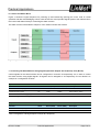
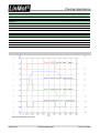
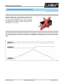
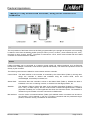
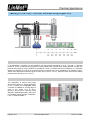
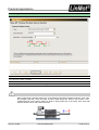
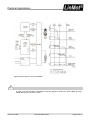
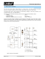
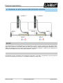
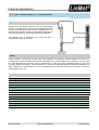
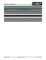
Figure 3 shows the signal sequence for powering up and referencing (homing) the motor, both in normal
operation and after acknowledging a fault. It also shows the most important signals (state of the relevant bits in
the Control and Status Word) for controlling the state machine.
The state machine is described in chapter 3 of the “Motion Control SW” manual.
Figure 3: Signals for controlling the state machine
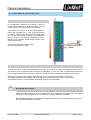
c. Controlling The State Machine Using Digital Inputs And Outputs On X4 (E1100) / X14 (B1100)
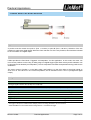
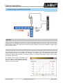
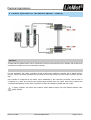
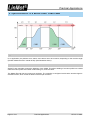
Control signals for the state machine can be configured on connector X4 respectively X14, in order to control
the state machine using digital signals. All signals can be assigned to X4 respectively X14 as desired. An
example of a configuration is below.
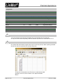
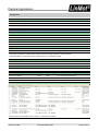
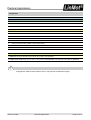
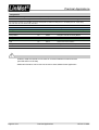
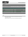
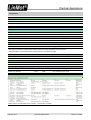
Inputs
\Parameters\Motion Control SW\Controller Configuration\X*.* I/O Definitions
Function
Value
E1100 (UPID)
B1100 (UPID)
Description
Ctrl Word: Switch On (Input)
On
1036h
62E8h
Switch On on X4.3 / X14.14
Ctrl Word: Home (Input)
On
1037h
62E9h
Home onX4.4 / X14.2
Ctrl Word: Error Acknowledge (Input)
On
1038h
62EAh
Error Ack on X4.5 / X14.15
Table 1: Configuration of the digital inputs on X4 (E1100) / X14 (B1100)
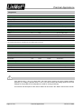
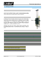
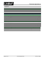
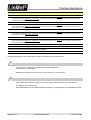
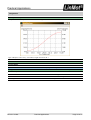
Outputs
\Parameters\Motion Control SW\Controller Configuration\X*.* I/O Definitions
Function
Value
E1100 (UPID)
B1100 (UPID)
Description
Status Word: Homed (Output)
On
1039h
62EEh
Homed on X4.6 / X14.17
Status Word: Error (Output)
On
103Ah
62EFh
Error on X4.7 / X14.5
Table 2: Configuration of the digital outputs on X4 (E1100) / X14 (B1100)
NTI AG / LinMot
Practical Applications
Page 5 of 47