1
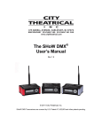
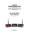
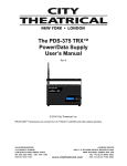
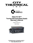
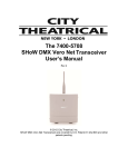
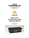
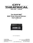
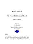
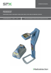
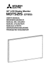
The MasterBlast™
User’s Manual
Rev 1.8
© 2008 City Theatrical, Inc.
SHoW DMX® Transceivers are covered by U.S. Patent # 7,432,803 and other patents pending.
2
Contents
Figures .........................................................................................................................................3
Tables...........................................................................................................................................3
Safety Notices .............................................................................................................................3
Introduction .................................................................................................................................4
CHAPTER 1, BASICS ..................................................................................................................4
Quick Start Guide........................................................................................................................5
CHAPTER 2, SETUP....................................................................................................................6
Assembling the MasterBlast Kit ..............................................................................................6
Connecting the MasterBlast to a Wired DMX Device .............................................................7
Color Kinetics CKDMX Output Pinout.....................................................................................7
Using the “Aux Power In” power input ....................................................................................7
CB Output Fuse ......................................................................................................................7
CHAPTER 3, OPERATING THE MASTERBLAST ......................................................................8
User Interface .........................................................................................................................8
The Routines Menu.................................................................................................................8
Color Wash EB ......................................................................................................................9
Color Wash ............................................................................................................................9
Cross Fade ............................................................................................................................9
Color Wave 6 Light ................................................................................................................9
Color Wave 12 Light ............................................................................................................10
Color Wave 18 Light ............................................................................................................10
Random Color......................................................................................................................10
Random Fade ......................................................................................................................10
Fixed Color ..........................................................................................................................11
Receive SHoW DMX ...........................................................................................................11
The Settings Menu................................................................................................................11
Grand Master.......................................................................................................................11
SHoW ID..............................................................................................................................11
Power...................................................................................................................................13
Panel Lockout ......................................................................................................................13
Backlight Time Out ..............................................................................................................13
RDM.....................................................................................................................................13
Firmware..............................................................................................................................13
miniZapi ...............................................................................................................................13
Restore Default?..................................................................................................................14
CHAPTER 4, THE CTI BATTERY BASE...................................................................................15
Features................................................................................................................................15
Charging and Discharging ....................................................................................................15
APPENDIX A: TYPICAL SYSTEM EXAMPLE DRAWINGS ....................................................17
APPENDIX B: COMPLIANCE INFORMATION ........................................................................18
System Compliance Information ...........................................................................................18
Radio Compliance Information..............................................................................................18
3
5692 SHoW DMX Radio CE Declaration of Conformity........................................................21
Figures
Figure 1, MasterBlast Label ..........................................................................................................4
Figure 3, MasterBlast Kit...............................................................................................................6
Figure 4, MasterBlast Back Panel.................................................................................................7
Figure 5, MasterBlast Front Panel ................................................................................................8
Figure 6, CTI 6280 Battery Base ................................................................................................15
Figure 7, A Wireless MasterBlast System...................................................................................17
Figure 8, Wireless MasterBlasts with wired PDS-750.................................................................17
Tables
Table 1, SHoW IDs .....................................................................................................................12
Table 2, Approved Antennas ......................................................................................................19
Safety Notices
Please read this entire manual before using your new equipment. Please keep the manual in a
safe place so you can refer to it in the future as required.
The CTI MasterBlast is intended for use only by qualified professionals. Connection, installation
and hanging of this equipment must be performed in accordance with all pertinent local, regional
and national safety codes and regulations.
The CTI MasterBlast is intended for indoor use only unless specified for outdoor use.
Keep the equipment dry. Do not operate the equipment if it gets wet.
Do not operate in excessive heat/direct sunlight.
Be sure installation provides adequate ventilation. Some system components can produce
significant heat and must be properly installed to allow proper cooling and assure user safety.
All sides of the equipment must be clear of obstruction and allow free airflow.
There are no user-serviceable parts inside. Refer to qualified service personnel.
RF Exposure: The antenna(s) used for this transmitter must be installed to provide a
separation distance of at least 20cm from all persons and must not be collocated or operating in
conjunction with any other antenna or transmitter.
4
Introduction
Thank you for selecting City Theatrical’s MasterBlast. Every effort has been made to anticipate
your questions in this manual, but if you have any questions that are not answered here, or you
want to discuss a special application, please feel free to contact us directly at City Theatrical.
CHAPTER 1, BASICS
The CTI MasterBlast can do many things, both as a stand-alone DMX Controller and as a
wireless DMX Power/Data Supply (PDS) for a single ColorBlast 12® TR 1 :
• The MasterBlast can control a single ColorBlast 12 TR1 plugged into its CKDMX output.
• The MasterBlast can transmit its stand-alone routines via SHoW DMX wireless DMX to
other SHoW DMX receivers, including other MasterBlasts.
• The MasterBlast can control wired DMX devices via its wired 5PXLR DMX output.
or
• The MasterBlast can receive wireless DMX from another MasterBlast, or from any other
SHoW DMX transmitter, and use it as a wireless Power/Data Supply (PDS) for a single
ColorBlast 12 TR1.
You can use the MasterBlast alone or in combination with many types of City Theatrical and
Philips Color Kinetics equipment to create an extremely wide variety of lighting systems and
effects!
Figure 1, MasterBlast Label
1
or any other Philips Color Kinetics CKDMX fixture
5
Quick Start Guide
Here is how to set up a basic MasterBlast system with six MasterBlasts running the Color Wash
EB Routine:
1. Assemble the MasterBlasts and connect the ColorBlast Cables to the CKDMX Output
connectors (see Assembling the MasterBlast Kit below for assembly instructions).
2. Locate the MasterBlasts where you want them to operate.
3. Power Up the MasterBlasts: Connect the Battery Base 24V Series Cables to the Battery
Bases and to the 24VDC CB Power (Anderson) Connectors on the MasterBlast
Controllers.
4. Configure one MasterBlast to be your Master controller:
a. Push the Enter button to go to the Routine Menu
b. Push the Down button to go to the Setup Menu
c. Push Enter to enter the Settings Menu
d. Push Down button to go to Restore Default?
e. Push Enter; the Display will read “Are You Sure?”, and push Enter again to
confirm
This MasterBlast is now configured as the Master controller, and is running and
broadcasting the Color Wash EB Routine on SHoW ID 1
5. Configure the other five MasterBlasts to be Receivers:
f. Push the Left button once to back out to the Routine Menu
g. Push the Down button to go to the Setup Menu
h. Push Enter to enter the Settings Menu
i. Push Down button to go to Restore Default?
j. Push Enter; the Display will read “Are You Sure?”, and push Enter again to
confirm
k. Push the Left button to go back to the Settings Menu
l. Push the Down button to go to the Routines Menu
m. Push the Enter Button to Enter the Routine Menu
n. Use the Up and Down buttons to scroll through the Routines, and stop at the
Receiver Routine
o. Push the Left button twice to go back to the Main Menu
The six MasterBlasts will now be operating, with the first one you configured controlling the
other five, and they will be running the Color Wash EB routine. They will all be communicating
wirelessly on SHoW ID 1.
6
CHAPTER 2, SETUP
Assembling the MasterBlast Kit
Place the ColorBlast on the CTI 6280 Battery Base™
with the MasterBlast on top of the ColorBlast’s
mounting base, with the CB mounting base hole and
MasterBlast mounting base hole centered over the
recessed nut in the Battery Base. Secure the
assembly with the (provided) ½” washer and bolt.
Tighten the bolt securely using a suitable socket
wrench so the fixture and MasterBlast remain in
place when the Kit is carried (see Figure 2).
Connect the ColorBlast’s 4PXLR Power/Data Cable
to the MasterBlast’s CKDMX Output (see Figure 3, if
the Power/Data cable is too long, you might want to
wrap it around the CB mounting base).
Figure 2
Connect the 24V Series Cable to the Battery base with the locking 4 pin Anderson Connector,
and connect the dual Anderson connector at the other end of the 24V Series cable to the dual
Anderson connectors marked “24VDC 2A CB Power In” on the MasterBlast (see Figure 3). The
MasterBlast will power up with the last used configuration.
Figure 3, MasterBlast Kit
7
Connecting the MasterBlast to a Wired DMX Device
Connect a DMX512 Cable to the MasterBlast’s DMX512 Output (see Figure 2), and connect the
other end of the DMX512 cable to the desired DMX device (be sure and provide appropriate
DMX termination at the end of the DMX chain controlled by the MasterBlast).
The MasterBlast outputs the same routine from its DMX512 Output that it is broadcasting, and
the wired DMX Output data is synchronized with the wireless DMX data. The DMX output is
disabled when the Receive routine is selected (see CHAPTER 3, OPERATING THE
MASTERBLAST, page 8).
Figure 4, MasterBlast Back Panel
Color Kinetics CKDMX Output Pinout
The MasterBlast CKDMX XLR 4P Output pinout is as follows:
PIN #
Pin 1
Pin 2
Pin 3
Pin 4
Signal
+24VDC
(n/c)
Data
DC Common
CK Cable Wire Color
Red
White
Black
This pinout matches Philips Color Kinetics ColorBlast 12 TR fixtures and all other CTI PDS units
and is the industry standard.
Using the “Aux Power In” power input
This power input can be used to operate the MasterBlast Controller if it is not being used with a
Battery Base. Connect a suitable 12-24VDC power supply (such as the CTI 5625 or 5627) to
power the MasterBlast alone. The MasterBlast will power up with the last used configuration.
Note: This input will not power a connected ColorBlast. If you need to power and operate a
ColorBlast with the MasterBlast, you must use the 24VDC 2A CB Power In connection for
power.
CB Output Fuse
The CKDMX output is protected by a 2A slow blow fuse (size 5x20mm). If the fuse blows, there
is probably a problem with the fixture or its cable. Correct the problem before replacing the fuse
and using the MasterBlast. If fuse replacement is necessary, be sure and replace with the
same type and value fuse.
8
CHAPTER 3, OPERATING THE MASTERBLAST
UP
L
E
F
T
ENT
R
I
G
H
T
DOWN
Figure 5, MasterBlast Front Panel
User Interface
The MasterBlast is provided with a button pad for user control and an LCD screen that displays
menu settings, configuration options, performance data, and any other text or graphics that
relate to unit function.
Press the Enter (center) button to access the menus, and press the UP or Down buttons to
move through the menus. When you reach a menu that you want to work in, simply press Enter
to begin editing. Press Enter again to save your changes.
If you pause in a menu, the system will time out and return to the Main Menu after 30 seconds.
The MasterBlast will power up in the configuration it was last set to. On power up, the unit will
be in the Main Menu and display will show:
MASTERBLAST Æ
[ROUTINE]
The arrow (Æ) indicates that there is more information available by pressing the Right button.
In a show routine, that information will include the routine name, the SHoW ID and current
battery voltage at the fixture. In the Receive routine, that information will include the routine
name (RECEIVE), the SHoW ID, received signal strength, and current battery voltage at the
CKDMX Output connector.
The Routines Menu
The MasterBlast provides nine routines, including eight show routines and one receive routine.
In the show routines, the MasterBlast outputs DMX data as a wired DMX signal and as a SHoW
DMX wireless broadcast, while in the Receive routine the MasterBlast receives and responds to
SHoW DMX wireless DMX Data (in the Receive routine, the wired DMX output is disabled).
In all show routines, the MasterBlast’s local CKDMX output is permanently addressed as DMX
1, 2, and 3 (RGB). In the Receive Routine, the CKDMX Output is mapped to a user selectable
DMX address set.
9
Color Wash EB
This show routine is a color wash routine in which the color changes and change rates have
been optimized for Extended Battery life (“EB”). Each MasterBlast Kit will run on Color Wash
EB (with the Grand Master at Full) for 13 hours with a fully charged battery base in good
condition 2 . The program executes a continuous cross fade between colors. The adjustable
parameter is the fade rate. To adjust the fade rate, go to the Color Wash EB routine and press
Enter. A blinking cursor will appear under the fade time. Adjust the fade time by pressing the
Up and Down buttons. Fade time is adjustable between .25 Seconds and 2 hours. MasterBlast
Controller will continually broadcast this routine via its internal SHoW DMX transceiver and will
output this routine on its DMX512 Output configured for RGB 3 color 8-bit personality.
Color Wash
This show routine is another color wash that has more color variation but is not optimized for
battery life. Each MasterBlast Kit will run on Color Wash (with the Grand Master at Full) for 7
hours with a fully charged battery base in good condition. The program executes a continuous
cross fade between colors. The adjustable parameter is the fade rate. To adjust the fade rate,
go to the Color Wash routine and press Enter. A blinking cursor will appear under the fade time.
Adjust the fade time by pressing the Up and Down buttons. Fade time is adjustable between
.25 Seconds and 2 hours.
MasterBlast Controller will continually broadcast this routine via its internal SHoW DMX
transceiver and will output this routine on its DMX512 Output configured for RGB 3 color 8-bit
personality.
Cross Fade
This show routine executes a continuous cross fade between two colors. Battery life with this
Routine will vary with the colors selected. The adjustable parameters are the fade rate and color
selection. To adjust the fade rate, go to the Color Fade routine and press Enter. A blinking
cursor will appear under the fade time. Adjust the fade time by pressing the Up and Down
buttons. Fade time is adjustable between .25 Seconds and 2 hours. To select the Colors for
the cross fade, go to the Color Fade routine and press the Right button. The display will change
to show the current Color 1 (C1) or Color 2 (C2) setting. The Color setting is displayed as Red
Green and Blue (RGB) levels in hexadecimal. Press the Enter button to edit the colors. A
blinking cursor will appear under the first character in the R level. Use the Up and Down button
to adjust. Use the Left and Right buttons to move to the other character fields. You can monitor
the level by watching a connected ColorBlast, as the output is updated while you adjust these
levels. When you have completed setting one color push Enter to record your setting and use
the Up and Down buttons to go to the other color.
MasterBlast Controller will continually broadcast this routine via its internal SHoW DMX
transceiver and will output this routine on its DMX512 Output configured for RGB 3 color 8-bit
personality.
Color Wave 6 Light
This show routine executes as a sequential color spectrum cross fade between six lights, where
the six lights are sequentially addressed (DMX1,2,3; 4,5,6; 7,8,9; etc.). The effect is of a color
spectrum or rainbow moving around the sequentially addressed fixtures. Each MasterBlast Kit
will run on Color Wave 6 Light (with the Grand Master at Full) for 7 hours with a fully charged
battery base in good condition. The adjustable parameter is the fade rate. To adjust the fade
rate, go to the Color Wave 6 Lgt routine and press Enter. A blinking cursor will appear under
the fade time. Adjust the fade time by pressing the Up and Down buttons. Fade time is
adjustable between .25 Seconds and 2 hours.
2
For peak battery life, the Battery Base must be properly charged an not have been over-discharged or
stored in a discharged state. See Charging and Discharging, page 15
10
MasterBlast Controller will continually broadcast this routine via its internal SHoW DMX
transceiver and will output this routine on its DMX512 Output configured for RGB 3 color 8-bit
personality.
Color Wave 12 Light
This show routine executes as a sequential color spectrum cross fade between 12 lights, where
the 12 lights are sequentially addressed (DMX1,2,3; 4,5,6; 7,8,9; etc.). The effect is the same as
Color Wave 6 Light except the Color Wave effect is smoother as it moves across more fixtures.
Each MasterBlast Kit will run on Color Wave 12 Light (with the Grand Master at Full) for 7 hours
with a fully charged battery base in good condition. The adjustable parameter is the fade rate.
To adjust the fade rate, go to the Color Wave 12 Lgt routine and press Enter. A blinking cursor
will appear under the fade time. Adjust the fade time by pressing the Up and Down buttons.
Fade time is adjustable between .25 Seconds and 2 hours.
MasterBlast Controller will continually broadcast this routine via its internal SHoW DMX
transceiver and will output this routine on its DMX512 Output configured for RGB 3 color 8-bit
personality.
Color Wave 18 Light
This show routine executes as a sequential color spectrum cross fade between 18 lights, where
the 18 lights are sequentially addressed (DMX1,2,3; 4,5,6; 7,8,9; etc.). The effect is the same as
Color Wave 6 Light and 12 Light except the Color Wave effect is even smoother than in the 6 or
12 Light versions. Each MasterBlast Kit will run on Color Wave 18 Light (with the Grand Master
at Full) for 7 hours with a fully charged battery base in good condition. The adjustable
parameter is the fade rate. To adjust the fade rate, go to the Color Wave 18 Lgt routine and
press Enter. A blinking cursor will appear under the fade time. Adjust the fade time by pressing
the Up and Down buttons. Fade time is adjustable between .25 Seconds and 2 hours.
MasterBlast Controller will continually broadcast this routine via its internal SHoW DMX
transceiver and will out put this routine on its DMX512 Output configured for RGB 3 color 8-bit
personality.
Random Color
This show routine executes changes (‘bumps”) between randomly selected colors. Each
MasterBlast Kit will run on Random Color (with the Grand Master at Full) for 7 hours or more
with a fully charged battery base in good condition. The actual battery life will vary with the
random pattern and step time. The adjustable parameter is the change rate. To adjust the
change rate, go to the Random Color routine and press Enter. A blinking cursor will appear
under the change time. Adjust the time by pressing the Up and Down buttons. Change time is
adjustable between .25 Seconds and 2 hours.
MasterBlast Controller will continually broadcast this routine via its internal SHoW DMX
transceiver and will output this routine on its DMX512 Output configured for RGB 3 color 8-bit
personality.
Random Fade
This show routine is similar to the color wash routine except that color selection is random.
Each MasterBlast Kit will run on Random Color (with the Grand Master at Full) for 7 hours or
more with a fully charged battery base in good condition. The actual battery life will vary with the
random pattern and fade time. The adjustable parameter is the fade rate. To adjust the fade
rate, go to the Random Color routine and press Enter. A blinking cursor will appear under the
fade time. Adjust the fade time by pressing the Up and Down buttons. Fade time is adjustable
between .25 Seconds and 2 hours.
MasterBlast Controller will continually broadcast this routine via its internal SHoW DMX
transceiver and will output this routine on its DMX512 Output configured for RGB 3 color 8-bit
personality.
11
Fixed Color
This show routine holds a single user selectable color. Battery life with this Routine will vary
with the colors selected. The Color setting is displayed as Red Green Blue Amber and White
(RGBAW) 8-bit levels in hexadecimal. Press the Enter button to edit the Red, Green and Blue
color levels or press the Right button and then press the Enter button to edit the Amber and
White color levels. A blinking cursor will appear under the first color level character indicating
that the field is in edit mode. Use the Up and Down button to adjust. Use the Left and Right
buttons to move to the other character fields. You can monitor the level by watching a
connected ColorBlast as the output is updated while you adjust these levels. When you have
completed setting the color press the Enter button to record your setting.
MasterBlast Controller will continually broadcast this routine via its internal SHoW DMX
transceiver and will output this routine on its DMX512 Output configured for RGBAW 5 color 8bit personality.
Receive SHoW DMX
This routine configures the MasterBlast Controller as a SHoW DMX controlled receiver and
individual Power/Data Supply (PDS) for a ColorBlast. In this routine the MasterBlast Controller
can receive wireless DMX control data from another MasterBlast Controller or from any DMX
source coupled to a SHoW DMX Transmitter. The user adjustable parameter is starting DMX
Address. All personalities (RGB3, RGB5 and RGBAW in 8-bit and 16-bit) are supported
automatically. Battery life for MasterBlast Kits set to Receive SHoW DMX will vary with the
routine selected for the controller.
The Settings Menu
Grand Master
Use the Grand Master to adjust the total system output level in percent. Grand Master settings
below 100% will increase battery life. The Grand Master is applied to the wired DMX, wireless
SHoW DMX, and (local) CKDMX outputs.
SHoW ID
The SHoW ID Setting configures the SHoW DMX Radio parameters, including hopping pattern
selection and full or limited bandwidth broadcast modes. All SHoW DMX equipment in a given
system must share the same SHoW ID in order to communicate. SHoW ID 1 is the default
setting for all SHoW DMX equipment.
12
There are 64 SHoW IDs. Each corresponds to a different combination of Hopping Pattern and
Broadcast Bandwidth settings. The SHoW IDs are defined in the table below:
Show
ID
1
2
3
4
5
6
7
8
9
10
11
12
13
14
15
16
17
18
19
20
21
22
23
24
25
26
27
28
29
30
31
32
Hopping
Pattern
1
2
3
4
5
6
7
8
9
10
11
12
13
14
15
16
1
2
3
4
5
6
7
8
9
10
11
12
13
14
15
16
Bandwidth
Full
Full
Full
Full
Full
Full
Full
Full
Full
Full
Full
Full
Full
Full
Full
Full
WiFi 1-6
WiFi 1-6
WiFi 1-6
WiFi 1-6
WiFi 1-6
WiFi 1-6
WiFi 1-6
WiFi 1-6
WiFi 1-6
WiFi 1-6
WiFi 1-6
WiFi 1-6
WiFi 1-6
WiFi 1-6
WiFi 1-6
WiFi 1-6
Show
ID
33
34
35
36
37
38
39
40
41
42
43
44
45
46
47
48
49
50
51
52
53
54
55
56
57
58
59
60
61
62
63
64
Hopping
Pattern
1
2
3
4
5
6
7
8
9
10
11
12
13
14
15
16
1
2
3
4
5
6
7
8
9
10
11
12
13
14
15
16
Bandwidth
WiFi 4-9
WiFi 4-9
WiFi 4-9
WiFi 4-9
WiFi 4-9
WiFi 4-9
WiFi 4-9
WiFi 4-9
WiFi 4-9
WiFi 4-9
WiFi 4-9
WiFi 4-9
WiFi 4-9
WiFi 4-9
WiFi 4-9
WiFi 4-9
WiFi 7-11
WiFi 7-11
WiFi 7-11
WiFi 7-11
WiFi 7-11
WiFi 7-11
WiFi 7-11
WiFi 7-11
WiFi 7-11
WiFi 7-11
WiFi 7-11
WiFi 7-11
WiFi 7-11
WiFi 7-11
WiFi 7-11
WiFi 7-11
Table 1, SHoW IDs
The ShoW DMX System supports 16 different Frequency Hopping Spread Spectrum (FHSS)
hopping patterns, full bandwidth broadcasting mode, and three different limited bandwidth
broadcasting modes. The SHoW IDs allow the user to quickly select the desired combination of
Hopping Pattern and Full or Limited Broadcast option that is desired. Please see The
Advanced Wireless DMX Broadcast Features of SHoW DMX in the SHoW DMX System User’s
Manual 3 for more about how these features can be used.
3
Available as a free download from the CTI website at www.citytheatrical.com
13
Power
This menu allows adjustment of radio broadcast power. For the 6410 MasterBlast Controller
(North American) the available power settings are 5mW, 10mW, 50mW, 100mW, or 125mW
FCC. For the 6411 MasterBlast Controller - CE, the power settings are 5mW, 10mW, 50mW or
100mW ETSI.
Panel Lockout
This setting allows the system to be locked after configuration to prevent accidental
reconfiguration in the field. To release panel lockout, press the Left and Right buttons at the
same time and hold until the display reads UNLOCKED.
Backlight Time Out
This menu setting allows adjustment of the Backlight time out. Available timeout settings
include Always OFF, Always ON, and 1-240 seconds.
RDM
Device Label: This label is user defined. You can edit the label by pushing the Enter button. A
blinking cursor will appear under the first character in the label. Use the Up and Down Buttons
to change characters and use the Right and Left buttons to move through the text string. Press
Enter again to record your label. For example, if you had MasterBlasts located in front of the DJ
Booth, you could give them RDM Labels like “DJ Boot Left” and “DJ Booth Right”
Unique ID: The RDM unique ID is factory set and unique for each RDM responder.
MasterBlast is a fully compliant RDM Receive Responder and can be monitored and configured
via wireless RDM using the SHoW DMX RDM Monitor (embedded in the SHoW DMX
Transmitter). The following device information is available via wireless RDM:
• Unique RDM ID (read)
• Device Label (set and read)
• Starting DMX Address (set and read)
• Battery voltage (read)
• Fuse status (read)
• SHoW ID (set and read)
• Broadcast Power (set and read)
• Receive signal strength (read)
For more details, see The SHoW DMX System User’s Manual.
Firmware
Displays the current firmware versions for the MasterBlast and internal SHoW DMX Radio
miniZapi
This feature sets configuration properties of the connected ColorBlast (or other CKDMX fixture).
• Set Address to 1: sets the connected fixture’s address to slot 1. The fixture will receive
8-bit RGB on slots 1-3, 8-bit RGBAW on slots 1-5, 16-bit RGBAW on slots 1-10, etc.
• Set DMX Mode: sets the connected fixture to receive DMX mode
• Set LED D4: sets the connected fixture’s speed to LED D4
• Set LED D3: sets the connected fixture’s speed to LED D3
• Set LED D2: sets the connected fixture’s speed to LED D2
• Set LED D1: sets the connected fixture’s speed to LED D1
• Set LED Fast: sets the connected fixture’s speed to LED Fast
• Set Ctrl. RGB5: sets the connected fixture’s color control to RGB5
• Set Ctrl. RGB3: sets the connected fixture’s color control to RGB3
• Set Ctrl. RGBAW: sets the connected fixture’s color control to RGBAW
• Set Tung. Curve: sets the connected fixture’s curve to Tungsten
14
• Set Normal Curve: sets the connected fixture’s curve to Normal
• Set Linear Curve: sets the connected fixture’s curve to Linear
• Set 8-bit Mode: sets the connected fixture to 8-bit color mode
• Set 16-bit Mode: sets the connected fixture to 16-bit color mode
Restore Default?
This menu restores all of the default settings of the MasterBlast:
• Routine: Color Wash EB
o Time 5 sec.
• Grand Master: 100%
• SHoW ID: 1
• Broadcast Power: 10mW
• Panel Lockout: Disabled
• Backlight Timeout: 10 sec.
15
CHAPTER 4, THE CTI BATTERY BASE
The CTI 12/24VDC Battery Base combines a pair of rechargeable 12VDC 7.2 AH Batteries with
a rugged mounting base. The Battery Base is provided with a special Series 24V Cable that
automatically wires the internal 12VDC batteries into a single 24VDC power source (the unit
may also be used with a standard CTI # 5656 Anderson Twofer to provide 14.4 AH of 12VDC
Power for use with SHoW DMX™ or other 12VDC equipment).
For Best Battery Life:
DO charge batteries immediately after use
DO top off each battery individually after
parallel charge is complete
DO NOT store discharged batteries
DO NOT discharge batteries below
10.5Vdc each
Not following these instructions
will reduce battery life
2
Battery Care Label
7
12/24V BATTERY BASE
3
B1 B2
R1 R2
6
1
Pin-Out Label Detail
4
5
Figure 6, CTI 6280 Battery Base
Features
The CTI Battery Base features are shown in Figure 6:
1. Pin-Out Label
2. Battery Care Label
3. Dual 12VDC Battery connection, 4P Anderson 30A Powerpole Locking connector
4. Dual Fuse holders (each battery is fused)
5. Handle with ½" hole for hardware connection (eg. C-Clamp)
6. Hole for safety cable installation
7. ½”-13 internal nut for attachment of MasterBlast Controller and LED Fixture
Charging and Discharging
The Battery Base should always be stored fully charged, and should be recharged immediately
after use. Storing a discharged Battery Base will reduce the unit’s usable life.
The CTI 5640 Autocharger can be used with a CTI # 5656 Anderson Twofer to charge both of
the Batteries in the Battery Base at the same time; however you should check each battery by
16
connecting it separately to the charger when the twofer-charge is completed, to assure that
each battery is fully topped off. For faster charging, one Autocharger can be used for each of
the batteries in the Battery Base.
A fully charged Battery Base in new condition will measure over 24VDC at the fixture when
connected to a complete live MasterBlast system (as displayed in the MasterBlast Main Menu).
The 7.2 AH 12VDC batteries in the CTI Battery Base are rated for 250 charge/discharge cycles
at 100% depth of discharge, which is 10.5VDC for each battery, or 21VDC total when both
batteries are measured in series. CTI Battery life estimates are based on this maximum
discharge value.
For maximum battery life, the batteries in the CTI Battery Base should not be discharged
beyond 100% depth of discharge. If batteries are discharged beyond 100% depth of discharge
(10.5/21VDC), battery life may be reduced. The symptom of over-discharge is that the batteries
will not re-charge to full voltage and they will not achieve the charge life that was available when
they were new. Worn out or damaged batteries may be replaced for a service charge by CTI;
contact City Theatrical for details.
17
APPENDIX A: TYPICAL SYSTEM EXAMPLE DRAWINGS
Figure 7, A Wireless MasterBlast System
Figure 8, Wireless MasterBlasts with wired PDS-750
18
APPENDIX B: COMPLIANCE INFORMATION
System Compliance Information
The City Theatrical 6411 MasterBlast is CE Certified
Standards Applied:
EN 55103-1, EN55103-2
EN 60950-1:2006
Product Conforms to CE Marking Directive 93/68/EEC
The City Theatrical 6410/6411 MasterBlast is RoHS compliant
The City Theatrical 6410/6411 MasterBlast is ETL and cETL Listed and conforms to UL STD 508A and is certified to CAN/CSA
STD C22.2 NO. 14-95
The City Theatrical 6410/6411 MasterBlast is an NEC 725 Class 2 Device
About the SHoW DMX Radios installed:
The City Theatrical 6410 MasterBlast is equipped with a City Theatrical 5691 SHoW DMX Radio which is FCC and IC
Certified for use in the US and Canada
The City Theatrical 6411 MasterBlast is equipped with a CE compliant City Theatrical 5692 SHoW DMX Radio which
is FCC and IC Certified for use in the US and Canada and is CE Certified for use in Europe
Radio Compliance Information
City Theatrical, Inc. # 5691 SHoW DMX Radio Transceiver
FCC ID: VU65691
7480A5691
IC ID:
City Theatrical, Inc. # 5692 SHoW DMX Radio Transceiver
FCC ID: VU65692
IC ID:
7480A5692
CE mark:
CE1177
FCC Part 15
This equipment has been tested and found to comply with the limits for a Class B digital device, pursuant to part 15 of
the FCC Rules. These limits are designed to provide reasonable protection against harmful interference in a
residential installation. This equipment generates, uses and can radiate radio frequency energy and, if not installed
and used in accordance with the instructions, may cause harmful interference to radio communications. However,
there is no guarantee that interference will not occur in a particular installation. If this equipment does cause harmful
interference to radio or television reception, which can be determined by turning the equipment off and on, the user is
encouraged to try to correct the interference by one or more of the following measures:
• Reorient or relocate the receiving antenna.
• Increase the separation between the equipment and receiver.
• Connect the equipment into an outlet on a circuit different from that to which the receiver is connected.
• Consult the dealer or an experienced radio/ TV technician for help.
Radio Frequency Notifications
FCC Notifications
RF Radiation The Product is an intentional radiator of Radio Frequency (RF) energy. In order to limit RF exposure to
personnel in the immediate area, the Product should be located and installed such that a separation of at least 20
centimeters is maintained between the Product’s antenna and personnel in the vicinity of the device.
Modification Warning
Caution: changes or modifications to this equipment, not expressly approved by City Theatrical Inc. could void the
user’s authority to operate the equipment.
Industry Canada Notifications
19
This Class B digital apparatus complies with Canadian ICES-003. Operation is subject to the following two conditions:
(1) this device may not cause interference, and (2) this device must accept any interference, including interference
that may cause undesired operation of the device.
Cet appareil numérique de la classe B est conforme à la norme NMB-003 du Canada.
Approved Antenna
To reduce potential radio interference to other users, the antenna type and its gain should be so chosen that the
equivalent isotropically radiated power (e.i.r.p.) is not more than that permitted for successful communication.
This device has been designed to operate with the antennas listed below, and having a maximum gain of 5 dB.
Antennas not included in this list or having a gain greater than 5 dB are strictly prohibited for use with this device. The
required antenna impedance is 50 ohms. Approved antennas are listed in the table below:
Manufacturer
Model
Type
1
Nearson
S151AH-2450S
Omni whip
2
Nearson
S141AH-2450
Omni whip
3
Centurion
WCP2400-MMCX4
Omni whip
4
Maxrad
MP24008XFPT
Panel
5
Maxrad
MP24012CPLXFPT
Panel
6
Maxrad
MYP24010PT
Yagi
7
Maxrad
MYP24014PT
Yagi
Connector
SMA plug reverse
polarity
SMA plug reverse
polarity
MMCX jack on 4” coax
pigtail
SMA plug reverse
polarity via provided
Antenna Cable
SMA plug reverse
polarity via provided
Antenna Cable
SMA plug reverse
polarity via provided
Antenna Cable
SMA plug reverse
polarity via provided
Antenna Cable
Gain
5dBi
2dBi
2.5dBi
8.5dBi
12dBic
10dBi
14dBi
Table 2, Approved Antennas
CE Mark Conformity
City Theatrical Inc. declares that this product conforms to the specifications listed in this manual, following the
provisions of the European R&TTE directive 1999/5/EC:
City Theatrical Inc. vakuuttaa täten että dieses produkt tyyppinen laite on direktiivin 1999/5/EY oleellisten vaatimusten
ja sitä koskevien näiden direktiivien muiden ehtojen mukainen.
City Theatrical Inc. déclare que le produit est conforme aux conditions essentielles et aux dispositions relatives à la
directive 1999/5/EC.
• EN 301 489-1, 301 489-17 General EMC requirements for Radio equipment.
• EN 60950 Safety
• EN 300 328 Technical requirements for Radio equipment.
CAUTION—This equipment is intended to be used in all EU and EFTA countries.
Outdoor use may be restricted to certain frequencies and/or may require a license for operation. Contact local
Authority for procedure to follow.
Note: ESD precautions should be used when attaching or removing the antenna.
Note: Combinations of power levels and antennas resulting in a radiated power level of above 100 mW equivalent
isotropic radiated power (EIRP) are considered as not compliant with the above mentioned directive and are not
allowed for use within the European community and countries that have adopted the European R&TTE
directive 1999/5/EC. For more details on legal combinations of power levels and antennas, contact City Theatrical
Inc.
Do not use this product near water, for example, in a wet basement or near a swimming pool.
Avoid using this product during an electrical storm. There may be a remote risk of electric shock from lightning.
Radio Frequency Notifications
Belgique Dans le cas d'une utilisation privée, à l'extérieur d'un bâtiment, au-dessus d'un espace public, aucun
enregistrement n'est nécessaire pour une distance de moins de 300m. Pour une distance supérieure à 300m un
20
enregistrement auprès de l'IBPT est requise. Pour une utilisation publique à l'extérieur de bâtiments, une licence de
l'IBPT est requise. Pour les enregistrements et licences, veuillez contacter l'IBPT.
France 2.4 GHz Bande : les canaux 10, 11, 12, 13 (2457, 2462, 2467, et 2472 MHz respectivement) sont
complétement libres d'utilisation en France (en utilisation intérieur). Pour ce qui est des autres canaux, ils peuvent
être soumis à autorisation selon le départment. L'utilisation en extérieur est soumis à autorisation préalable et très
restreint. Vous pouvez contacter l'Autorité de Régulation des Télécommunications (http://www.art-telecom.fr) pour de
plus amples renseignements.
21
5692 SHoW DMX Radio CE Declaration of Conformity