1
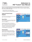
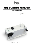
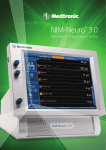
HQ
Installation and Operation
Copyright©2013 Handi Quilter, Inc. All rights reserved. Printed in the U.S.A. 08/2013
®
Table of Contents
Contents of the HQ HighRise kit
3
Installation6
Operation of the HQ HighRise
12
Troubleshooting15
2 | HQ High Rise Instructions
08/26/13
www.HandiQuilter.com
Contents of the HQ HighRise™ kit
The HQ HighRise works with the straight-leg HQ Studio Frame and HQ Fusion Frame systems. Be sure to
verify that you have the straight-leg frames and not the slanted legs on your frame.
Item Part Number(s) Quantity A. actuators with cable
QT10800
6 (labeled 1-6)
B. saddle brackets
QT10817
6
C. top-left brackets
QT10815
6
D. top-right brackets
QT10816 6
E. extension cables
of different lengths
QT20110-170 (#5)
QT20110-146 (#6)
QT20110-113 (#4)
QT20110-65 (#3)
4 (labeled 3-6)
F. controller with
mounting plate
QT20105
1
www.HandiQuilter.com
08/26/13
Photo
HQ High Rise Instructions | 3
Item Part Number(s) Quantity G. power supply
QT20110
1
H. power cord
QM20277
1
I. cable ties
not applicable
18
J. adhesive tie-wrap pads
not applicable
12
K. fir-tree plugs
not applicable
4
L. cable sheath
not applicable
2
M. M6 x 55mm screws
QT10813
6
4 | HQ High Rise Instructions
08/26/13
Photo
www.HandiQuilter.com
Item Part Number(s) Quantity N. M6 x 50mm screws
QT10819
6
O. M6 x 35mm screws
QT10812
6
P. M6 x 16mm screws
QT10811
24
Q.
QT20108
1
wireless key fob
Ü
Photo
IMPORTANT: The key fob has been synchronized with your controller. It will not work with another
HQ HighRise controller.
Tools required
•
•
•
•
•
Screwdrivers: Phillips screwdriver and flat-blade screwdriver
Small, adjustable wrench
5mm hex wrench, or if available, a 5mm hex-head drill bit mounted in a cordless drill
Level (optional)
Isopropyl alcohol to wipe the frame before attaching adhesive tie-wrap pads
www.HandiQuilter.com
08/26/13
HQ High Rise Instructions | 5
Installation
To prepare the frame legs for the HQ HighRise
1. Lower the frame to its lowest position.
Ü
I MPORTANT: Before proceeding, make sure the frame
is level from front to back and from side to side. Use a
spirit, or bubble, level if you have one available. If you
need to adjust the leveling feet on the frame, use the
17/13/16mm wrench that came with your frame.
2. R
emove the frame’s leg latches. Use a #3 hex wrench and
an adjustable wrench (or 5/16-inch socket wrench) to
remove all of the leg latches.
!
Ü
CAUTION: Be careful when removing the screw
because the spring is under a slight tension.
IMPORTANT: Keep the leg latches, springs, and screws
in case you need to remove the HQ HighRise system.
To prepare the actuators for installation
Mount the saddle bracket to the non-motor end of all six
actuators with M6 x 35mm screws. Slide the screw through
the flat hole on the bracket, then through the opening on the
actuator, and out through the hole on the other side of the
bracket, tightening as you go.
Motor
The number of actuators you will install to the frame depends
on the size and configuration of your frame.
• If you have a 12-foot frame or a 10-foot frame, use
all six actuators (numbers 1 through 6) – one each on the
front and back of the side legs and one on each of the
center legs.
• If you have an 8-foot frame or a 6-foot frame, use five
actuators (numbers 1, 2, 3, 4, and 5) – one each on the front
and back of the side legs and one on the center leg.
M6 x 35 mm
screw
Saddle bracket
• If you have an 4-foot frame, use four actuators (numbers 1,
2, 3, and 4) – one each on the front and back of the side legs.
6 | HQ High Rise Instructions
08/26/13
www.HandiQuilter.com
Use the following diagrams to determine which actuator to mount to each leg of the frame. Lay each of the
prepared actuators next to the leg to which it will be mounted and double check before proceeding.
Actuator #5
Actuator #1
Actuator #6
Actuator #4
Actuator #2
Actuator #3
Actuator #4, mounted behind
left-center leg
Front of 12-foot or 10-foot frame
Actuator #4
Actuator #1
Actuator #5
Actuator #2
Actuator #3
Front of 8-foot or 6-foot frame
Actuator #3
Actuator #1
Actuator #4
Actuator #2
Actuator #3, mounted behind
right-center leg
Ü
Front of 4-foot
!
IMPORTANT: The photograph above shows
the Studio Frame. If you have a Fusion Frame,
the center legs have two vertical posts.
Mount the actuator behind the front post of
each center leg.
NOTE: The controller can be mounted on the left side or the right side of the frame. These
instructions show photographs for mounting the controller on the right side of the frame. If you
mount the controller on the left side of the frame, reverse the actuator numbers and positions (e.g.
put actuator #1 on the back-left side leg, put actuator #2 on the front-left side leg, etc.). However, you
should still connect the cables into the controller according to their numbers as described later.
www.HandiQuilter.com
08/26/13
HQ High Rise Instructions | 7
To mount the actuators to the frame’s legs
Follow steps 1 through 7 to mount each actuator required for the size and configuration of your frame.
1. P
lace the bottom saddle bracket over the
inside bottom frame tube with the motor
side of the actuator facing away from
the leg.
Motor
Saddle bracket
2. T ilt the bottom of the actuator (saddle bracket end) away from the leg and place the right and left top
brackets around leg and over the top of the motor end of the actuator.
3. Insert a M6 x 50mm screw between
the right and left top brackets and
loosely fasten.
Loosely fasten
the right and left
top brackets.
4. Insert four M6 x 16mm screws to clamp the
right and left top brackets together around
leg tube and loosely fasten.
Loosely fasten
the four 30mm
screws.
8 | HQ High Rise Instructions
08/26/13
www.HandiQuilter.com
5. Push the bottom of the actuator so the actuator is parallel to the leg.
6. Fully tighten all screws.
7. Insert a M6 x 55mm screw under the bottom frame tube and tighten.
8. Repeat steps 1 through 7 for each actuator you install.
To lay out and connect the cables
1. L ay out extension cables #5 (longest), #6 (next longest), #4, and #3 (shortest) on the floor behind the
frame. Make sure the cables are oriented such that the connector
ends can be plugged into the actuators.
2. C
onnect the numbered extension cables to the #5, #6, #4, and #3
actuator cables. If youa re using fewer actuators, connect extension
cables to only those actuators.
3. P
ull the other ends of extension cables over to the right front side
of the frame. (They will be connected to the controller later in the
setup.)
www.HandiQuilter.com
08/26/13
HQ High Rise Instructions | 9
To mount the controller to the side of the frame
1. Remove the front poles from the frame’s pole brackets.
2. U
se a small, adjustable wrench to remove two bolts from the
front right side of the pole brackets.
3. Insert the bolts you just removed through controller’s
mounting plate and place the bolts back into the front right
side of the pole brackets. Tighten the bolts.
To connect cables and power supply 1. C
onnect the #1 and #2 actuator cables to labeled connectors
#1 and #2 on the controller.
2. C
onnect extension cables #3, #4, #5, and #6 to labeled
connectors on the controller. Connectors #7 and #8 are open
(nothing connected).
3. L ay the power supply inside the right-front bottom frame
tube.
4. C
onnect the power supply cable to the controller. Wrap the
power supply cord around the front-right leg and use cable
ties to secure the power supply cable near the controller.
Ensure there is sufficient slack in the cable to allow for raising
the frame.
5. C
onnect the power cord to the back of the power supply.
10 | HQ High Rise Instructions
08/26/13
www.HandiQuilter.com
6. U
se one piece of cable sheath to bundle cables 1, 2, and 3 connected
to the controller. Trim the sheath if necessary with a pair of scissors.
7. U
se one piece of cable sheath to bundle the cables 4, 5, and 6
connected to the controller
!
NOTE: Trim the sheath to appropriate length, if necessary,
with scissors.
8. P
ull the cables with sheaths behind and underneath the right upper frame tube and push a fir-tree plug
into any empty screw hole and then use a cable tie to secure the cable bundles
Fir-tree
plugs inserted into
open screw
holes in the
frame.
Cable ties
inserted
into firtree plugs
and then
wrapped
around
cables.
9. U
se adhesive tie-wrap pads
and cable ties to secure cable
bundles to the back of the
frame.
!
NOTE: To ensure good adhesion, wipe
the frame with isopropyl alcohol and allow it to dry
before sticking the adhesive tie-wrap pad.
www.HandiQuilter.com
08/26/13
HQ High Rise Instructions | 11
Operation of the HQ HighRise
The HQ HighRise is simple to operate.
Lift height LEDs
Raises the
frame to its
maximum
height.
Set three preset heights.
Then select
the button for
the height you
want.
Lowers the
frame to its
lowest position
Fault LED (Red)
First-time operation
1. P
lug in the power cord from power supply to an outlet. At least one LED on the controller will light,
indicating power is on.
2. P
ress the green up arrow button for a few seconds. All actuators should lift. If not, refer to the
troubleshooting section of this manual.
3. P
ress the blue down arrow button for a few seconds. All actuators should lower. If not, refer to the
troubleshooting section of this manual.
Your HQ HighRise is now operational.
!!
!
Ü
C
AUTION: When the actuators are extended, there may be a small amount of oil on the inside
actuator tube. This is normal. Keep fabrics and other objects away from these inside tubes.
NOTE: When the actuators are extended, there may be a small amount of oil on the inside actuator
tube. This is normal. Keep fabrics and other objects away from these inside tubes.
IMPORTANT: The actuators have a 10% duty cycle which requires that the HQ HighRise is not
operated constantly. The actuator motors may overheat if the system is run constantly.
12 | HQ High Rise Instructions
08/26/13
www.HandiQuilter.com
To raise the frame
• P
ress and hold the green up button until the frame raises to your desired height. It will be at its
maximum height when all eight LEDs are lit and motion has stopped because the frame can’t go any
higher.
• A
lternately, press and hold the top button on the key fob for longer than one second and until the
frame raises to your desired height.
To lower the frame
• P
ress and hold the blue down button until the frame lowers to your desired height. It will be at its
lowest position when a single LED is lit and motion has stopped because the frame can’t go any lower.
• A
lternately, press and hold the bottom button on the key fob for longer than one second and until the
frame lowers to your desired height.
To customize the three preset frame heights
Preset three frame heights and quickly recall a height by pressing one of the preset buttons.
1
. Set the frame to the desired height using the up (green) and down (blue) buttons.
2. Press and hold one of the three preset buttons for two to three seconds. The LED above the button
will blink, then the LED will stay illuminated indicating the button is programmed.
3. Repeat these steps for the other two buttons with two other preset frame heights.
To recall a preset frame height
• Q
uickly press one of the preset-height buttons. The HQ HighRise will adjust the frame to
the preset height.
www.HandiQuilter.com
08/26/13
HQ High Rise Instructions | 13
To use the wireless key fob
The hole indicates the
top of the key fob.
Press and hold
for longer than
a second to
raise the frame.
Quickly press to move the
frame to preset-height A.
Quickly press to move the frame
to preset-height B.
Press and hold for
longer than a
second to lower
the frame.
Quicly press to move the
frame to preset-height C.
To use the key fob to raise or lower the frame
• P
ress and hold the top button for longer than a second to raise the frame. When the frame is at the
desired height, release the button.
• P
ress and hold the bottom button for longer than a second to lower the frame. When the frame is at
the desired height, release the button.
To use the key fob to adjust the frame to a preset height
• Q
uickly press one of the buttons on the key fob. The HQ HighRise adjusts the frame to the preset
height. The top button adjusts the frame to preset-height A; the middle button adjusts the frame to
preset-height B; and the bottom button adjusts the frame to preset-height C
!
NOTE: When the actuators are extended, there may be a small amount of oil on the inside actuator
tube. This is normal. Keep fabrics and other objects away from these inside tubes.
14 | HQ High Rise Instructions
08/26/13
www.HandiQuilter.com
Troubleshooting
Your HQ HighRise requires no maintenance
Troubleshooting
Problem or Symptom Fault LED (red) is illuminated
Corrective Measure
Fault LED (red) is illuminated Look at the lift height
LEDs. The illuminated LED indicates which actuator has
a fault. The bottom LED corresponds to actuator 1; the
second LED from the bottom corresponds to actuator
2; and so forth for the bottom six LEDs.
Disconnect the power cord from the wall socket and
check all of the cable connections, including the extension cables. Reconnect the power cord.
If the red fault LED is no longer illuminated, try to raise
or lower the frame. If the red fault LED comes on,
disconnect the power cord from the wall and call Handi
Quilter technical support.
Fault LED (red) is illuminated.
LED 7 (second lift height LED from the top) is
illuminated.
One (or more) of the actuators or extension cables is
not plugged in. Disconnect the power cord from the
wall socket and check that the cables are plugged
into the correct connectors on the controller. See To
connect cables and power supply and the two notes
marked IMPORTANT on page 8 for more information.
Reconnect the power cord and confirm that LED 7 and
the fault LED are no longer illuminated.
One or more actuator(s) have stopped lifting
or lowering the table.
Stop pressing buttons on the controller. Disconnect the
power cord from the wall socket and call Handi Quilter
technical support
Actuators raise or lower the table with an
uneven, nonlevel motion.
Stop pressing buttons on the controller. Disconnect the
power cord from the wall socket and call Handi Quilter
technical support
www.HandiQuilter.com
08/26/13
HQ High Rise Instructions | 15