1
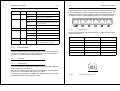
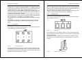
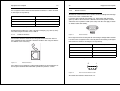
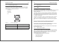
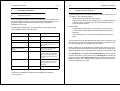
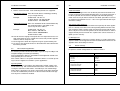
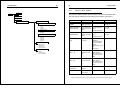
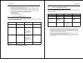
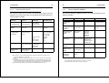
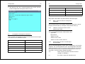
1
Index
P3 - Portable Data/Voice Extension System
Installation and Operation Manual
Defence Communications Industry Pty Ltd
Tel +613 9850 6110 Fax +613 9850 6113
[email protected]
- September 2006 -
Side
1
Preface
5
1.1
1.2
1.3
1.4
Overview
General Information on P3 System Documentation
Safety
Acronyms and Definitions
5
5
5
7
2
The P3 Concept
9
2.1
2.2
2.3
Introduction
Feature Overview
Application
9
12
14
3
Equipment Description
16
3.1
3.2
3.2.1
3.2.2
3.2.3
3.2.4
3.3
3.3.1
3.3.2
3.3.3
3.3.4
3.3.5
3.3.6
3.4
3.4.1
3.4.2
3.4.3
Frontpanel Layout
Control and Monitoring Elements
Keypad Block
System Status Display
LED Signaling
Acoustical Alarm
Interfaces
LAN Interface
Line Interface
POTS Interface
Handset Interface
RS232 Interface
DC Power Supply Interface
Miscellaneous
Battery
External AC/DC Adaptor
POTS Handset
16
18
18
21
22
23
23
23
25
26
27
28
29
30
30
30
31
2
3
4
Installation Instructions
33
6
Warranty Details
64
4.1
4.2
4.3
4.4
4.5
4.6
4.7
4.8
4.9
Unpack and Inspect
General Installation Guidelines
ADSL Connection Setup
Spanning Tree Function Setup
Ethernet Bridge Setup
Point-to-Point Field Telephone Function Setup
VoIP based Network Telephone Function Setup
Mixed P3/P1 Applications
Default Settings
33
34
35
35
36
37
38
39
40
6.1
6.2
6.3
6.4
6.5
6.6
Provisions of warranty
Limited Warranty
Repair Turnaround Time
Product Return
Billing
Recycling information
64
65
65
65
66
66
5
Configuration
42
5.1
5.1.1
5.1.2
5.1.3
5.1.4
5.1.5
5.2
5.3
5.4
5.4.1
5.4.2
5.4.3
5.4.4
5.4.5
5.4.6
5.4.7
5.4.8
5.5
Management access via LCD menu
Submenu ADSL PORTS
Submenu ETHERNET PORT
Submenu NETWORK SETTINGS
Submenu Voice over IP
Submenu MISCELLANEOUS
Management access via the RS232 interface
Remote Management access via Telnet
Description of management commands
HELP - Overview about all management commands
VERSION - Display of current version (administrative data)
SHOW Display of Status and Configuration information
SET -Configuration settings
STATS - Display of statistics
CLEAR - Clears statistic counters
PING – Network connectivity testing
REBOOT – Software Restart
Software Download
42
46
47
48
49
50
51
54
55
56
56
56
58
59
60
61
61
61
Annex
Product Specifications
67
Annex A
Annex B
Annex C
Annex D
Hardware Features
Software Features
Mechanical Characteristics
Environmental Conditions
67
69
69
70
Preface
5
1
Preface
1.1
Overview
General Information on P3 System Documentation
The documentation concept for the P3 system covers a number of individual documents ( see Individual documents and ID numbers)
Document
Abbreviation
Id no.
Data Sheet English
DBe
951931
System Description
English
SYSe
951933
User Manual English
IOMe
951935
Table 1
1.3
Preface
The following rules must be observed to keep the technically unavoidable
residual risk to a minimum
We are pleased with your choice of our product P3 – Portable RADSL
Communications System.
The purpose of this handbook is to provide an overview of the P3 system
and to describe the installation, operation and maintenance procedures.
Carefully reading these following instructions, will enable you to quickly
familiarise with diverse features and advantages of this advanced broadband communications system.
1.2
6
Individual documents and ID numbers
Safety
The P3 system has been developed with the latest technology and high
degree of operational safety including compliance with the latest
ISO 9001 standards.
The system is safe in normal operation. There are however, limited
sources of danger that mustnot be neglected: inside the device exist
dangerous currents and due care must be excercised. DCI recommends
only experienced personnel to access P3's internal components.
• installation, commissioning, configuration and de-installation solely
by skilled personal using the relevant documentation; the user
must have read and understood installation, operation and safety
instructions,
• P3 system must be connected to earth ground by using the terminal screw attached to the front panel before connecting any external cabling,
• no smoking, no open flames, no sparks during battery charging
process in close neighborhood to the unit
• in case of using the supplied AC/DC adapter it must be ensured
that AC power plug fits securely into the AC outlet and that the
voltage and frequency ratings indicated in this manual will correspond to the AC power source,
• in case of using any alternative external power suppliy (e.g. generator car battery, solar panel) it must be ensured that the produced
voltage corresponds to the specified P3 DC input voltage range
(see 3.3.6 / page 29),
• transport, storage and operation of the system solely under the
specified environmental conditions (see Annex D / page 70),
• direct contact with water has to be avoided.
never place the device or any auxiliary part (e.g. AC/DC adapter) in
a location where the danger exists that water would be able to
penetrate into the device,
• the external AC/DC adaptor must not be applied under conditions
of high relative humidity above 95% or condensation
• if a device with ground connection (e.g. PC desktop with protection
earth) shall be connected to the RS232 interface the phone selector switch must be in position "VoIP" (this safety rule does not
apply to devices without earth connection),
• operation of the system only in perfect working order:
in case of following situations the device has to be disconnected
from the power supply and sent to repair:
- the power cable or connector are worn or damaged,
Preface
7
- water or other liquids penetrated the device,
- the case is damaged
- the device shows striking deviations from normal operation
CE Marking:
The P3 RADSL Communication System conforms to the following European directives:
8
Preface
RJ45
8 pin connector/socket type
RS232
Serial Interface
RTP
Real Time Transport Protocol
Sub-D
Physical connector type
TELNET
TCP/IP oriented terminal program
Safety:
CENELEC EN 60950
TFTP
Trivial File Transfer Protocol
EMC:
CENELEC EN 55024
CENELEC EN 55022
TxHIGH
ADSL transceiver unit transmitting at high data
rate
The CE mark is affixed to the system to indicate conformity with these directives.
TxLOW
ADSL transceiver unit transmitting at low
speed
1.4
UTP
Unshiedled Twisted Pair
VoIP
Voice over IP
Acronyms and Definitions
100Base-TX
100 Mbps Twisted Pair Ethernet
10Base-T
10 Mbps Twisted Pair Ethernet
ADSL
Asymmetric Digital Subscriber Line
DMT
Discrete Multitone
H.323
VoIP protocol suite defined by International
Telecommunications Union
HDLC
High Level Data Link Control Protocol
LAN
Local Area Network
LCD
Liquid Crystal Display
LED
Light Emission Diode
MAC
Medium Access Control Protocol
MDI
Medium Dependent Interface
MDI-X
MDI with internal crossover
P3
Portable RADSL Communications System
PBX
Private Branch Exchange
POTS
Plain Old Telephone Service
RADSL
Rate-Adaptive ADSL
The P3 Concept
2
The P3 Concept
2.1
Introduction
9
10
The P3 Concept
transceiver transmitting in lowstream direction is denoted as TxLOW.
Each physical RADSL interface of a P3 system can be configured according to the real needs in a network configuration.
In the world of modern and diversified data applications, rapidly established communications links of high bandwidth are in increasing demand.
This is particularly prominent in areas where no clear line of sight exist
for radio signals to propogate or laying of fibre-optic cable is difficult.
P3 were designed in close collaboration with Australian Army Signallers
(RASC) specifically to overcome problems of establishing comms infrastructure in difficult terrain. In short, P3 is a soldier friendly device designed
for fast and effective data and voice links set up over copper cables
(or DON10) - without loss of functionality, compared to fibre-optic networks.
The P3 (P for Portable; 3 independent RADSL transmission channels) is a
stand alone communication system for data and voice links extensions:
capable of 8Mbs throughput over 8Kms of copper cables.
The asymmetric tranmsission channels can be configured for high and low
(or Master and Slave) data transmission independently. This is shown in the
Figure 1 below.
Let's assume a simple point to point links must be established: consisting
of 2 x P3s indicated by P3-a and P3-b and interconnected by one twisted
copper pair. In configuration A, the asymmetric transmission capability is
set for high bit rate transmission from P3-a to P3-b and low bit rate transmission from P3-b to P3-a. This is indicated by "highstream" and "lowstream" accordingly. In configuration B the opposite directions for
"highstream" and "lowstream" are adjusted. The RADSL transceiver
transmitting in highstream direction is denoted as TxHIGH whereas the
Figure 1
Definition of highstream and lowstream bitrates
In the highstream direction data rates up to max. 8 Mbps are achieved; for
lowstream direction maximum data rates up to 1 Mbps can be achieved.
The multiport 100/10Base-T auto-negotiating Ethernet interface for symmetrical UTP cabling allows for universal interconnection of Ethernet LAN
or PCs equipped with Ethernet adapter. The P3 features integrated transparent bridge functionality which is interfaced to the three RADSL lines.
Each P3 unit contains an integrated telephone handset for voice communications over the same copper cable as used for data, independently of
the LAN traffic and even to LAN failures. This can be used to connect P3
to e.g. a PBX as well as for direct field telephone communication between
adjacent P3s. Additional Voice over IP based network telephone function
allows for secure voice communication in a meshed network to any other
P3 location or even PCs connected to the network.
The P3 Concept
11
12
P3 is easily configured via the integrated tactile membran keypad and
LCD display, thus no external computers are required. Furthermore a remote management is provided from any PC without the need of installating any dedicated management software.
2.2
The P3 Concept
Feature Overview
Hardware Features
• 3 independent rate-adaptive RADSL DMT transceivers
The units’s functionality can be greatly extended by connecting auxiliary
units (video cameras, encryption modules etc.) to the Ethernet interface.
• each transceiver can be configured for TxHIGH or TxLOW mode
independently
P3 can operate on the internal battery capable of up to 8 hours of operations under full load conditions (significantly longer with only one or two
RADSL channels in use). Apart from the internal power supply P3 offers
a number of external powering options, like AC/DC mains adapter, car
batteries, generators or solar panels.
• 6-port auto-negotiating 10 Base-T/100 Base-TX Ethernet interface
The following Figure 2 shows the P3 system layout with the main controls.
• field telephone function – for independent point-to-point voice communications over the same copper line as used for data
• POTS splitter provides a simultaneous voiceband channel
• keypad with tactile membrane control buttons
• antiglare black-on-green LCD display
• voice-over IP (VoIP) based network telephone function
• power supply by internal battery or external AC/DC adapter or
alternative DC power source inputs
• up to 8 hours battery backup,
• LED indication of battery/mains feeding, battery charging, ADSL
and Ethernet link and data transmission status
• sophisticated power management function feeding only those units
which are in operational mode
• interconnection panel with spring loaded binding posts
• shock absorbent ruggedised casing, in-built carry handle
• operation with closed lid possible
Software Features
• Ethernet transparent Multiport Bridge
Figure 2
P3 Mechanical Layout
P3 is fully compliant with the P1 (single RADSL channel LAN extension)
system, ensuring flexible and cost effective configurations. Please refer to
4.8 / page 39 for detailed information how to operate P1 and P3 in common system applications.
• Self-learning bridging algorithm (dynamic update of bridge lookup
table)
• Spanning Tree Algorithm
• HDLC Encapsulation of MAC frames
The P3 Concept
13
• Configuration & supervision software supporting menu driven commands
• VoIP software stack (H.323 & RTP)
• TELNET based remote management access
• Software download via TFTP
14
2.3
The P3 Concept
Application
P3 offers many possibilities in the way the system can operate. From a
simple point to point transparent LAN link to a complex web of “P3”s, including a data repeater, effectively extending the reach of “P3” from 5 to
10Kms to 15Kms, etc., see Figure 3 below.
• Extended diagnostics and testing functions via RS232 interface
Figure 3
P3 Field Deployment Configurations
The P3 Concept
15
The main application of the system are:
• field deployed LAN networks, especially where no other data infrastructure exist or possible,
16
Equipment Description
3
Equipment Description
3.1
Frontpanel Layout
• general LAN network extensions and back-ups,
• telemetry applications where a rapid deployment of data networks
is essential, including defence, fire brigades, police, mining, telemedicine, remote instrumentation control and monitoring.
This section summarizes all interfaces, control and supervising elements
of P3. Detailed information about it will be provided in the subsequent sections.
• range extender (P3 Repeater configuration) for up to 5 km with
every hop.
Figure 4
P3 Frontpanel Layout
LCD Display:
Provides P3 status and responses to the keypad management functions.
Equipment Description
17
Keypad:
9 tactile membran keys supporting following functions:
• on/off switch,
• contrast control of LCD display,
18
Equipment Description
Ground Terminal:
Connects P3 to earth ground.
3.2
Control and Monitoring Elements
3.2.1
Keypad Block
• LCD menu navigation keys,
• ringing button for point-to-point telephone function.
Line Interface:
Spring loaded binding posts for easy connection of up to three copper
lines.
The tactile membrane control buttons are arranged in a ‘3x3’ push button
structure (see Figure 5).
ADSL LED block:
Indicates link and data transmission status of ADSL transceivers.
POTS Interface:
Enables transparent usage of the line for voiceband applications.
Handset Interface:
Connecting the integrated handset or ordinary POTS set for VoIP based
network telephone or point-to-point field telephone function.
Handset:
Ruggedized POTS handset with integrated dialing block.
Telephone mode selector switch:
Selection of desired telephone function – VoIP based network telephone
or point-to-point field telephone function, respectively.
Figure 5
From a functional point of view according to Figure 6 the four grey shadowed buttons are used for hardware related functions, while the white
background buttons are used for LCD menu control.
LOWER
CONTRAST
Ethernet Interface:
6 LAN ports available operating at 10Base-T or 100Base-Tx Ethernet
mode. Attached LEDs indicate link and data transmission status.
RS232 Interface:
Useful for extended maintenance and diagnostics functions (e.g. software
download)
Power Supply interface:
For all DC input sources in voltage range between 10V and 45 V. Attached LEDs indicate power status and voltage polarity mismatch.
P3 Keypad Arrangement
UP
INCREMENT VALUE
HIGHER
CONTRAST
LEFT
MENU / SEL
RIGHT
DECREMENT VALUE / ESCAPE
VALIDATION / MAIN MENU
EXECUTE / INCREMENT VALUE
DOWN
Ringing Button
POWER ON / OFF
Figure 6
DECREMENT VALUE
Functional Description of P3 Keys
Equipment Description
19
The two corner buttons on the top control LCD contrast. It is worthful to
adjust them to optimize LCD visibility under different ambient light conditions.
20
Equipment Description
The parameter setting mode can be abandoned by scrolling through the
displayed parameter list until no further parameter is available in the respective direction.
On the bottom left corner the power on/off switch is located.
In point-to-point field telephone function the ringing button on the bottom
right corner can be pressed in order to call the opposite P3 at the line
where the phone selector switch is directed to.
The remaining white background buttons in the figure above provide software control of P3.
By pushing the menu key (centre key) the program changes into the control mode. The main menu is displayed. The respective active menu item
will be displayed highlighted by a blinking cursor.
During active control mode the keypad is interpreted as follows:
• “UP” or “DOWN”: the complete menu is scrolled accordingly in a
circular way
• “RIGHT”; executes current menu selection which may result for
lower-level menu selection or execution of selected command.
• “LEFT” return to previous upper-level menu selection or return
from main menu to status display mode.
• “MENU” return to main menu
During parameters setting mode the buttons are programmed for selection of parameter and for setting the corresponding parameter values.
In this case the keys indicated by “UP”, “DOWN”, “LEFT” and “RIGHT”
have to be used for selecting the parameters in the direction as listed on
the display (i.e. in the case of parameters being listed vertically “UP” and
“DOWN” have to be used and, in the case of parameters being listed horizontally “LEFT” and “RIGHT” have to be used). Singular parameters have
to be regarded as listed vertically.
Selected values are entered by pushing the “SEL” key (centre keypad button). Moving to next menu without pushing “SEL” will ignore the selected
settings.
Parameter arrangement
Key
Vertical order
Horizontal order
RIGHT
Increment parameter value
Previous parameter
LEFT
Decrement parameter value
Next parameter
UP
Previous parameter
Increment parameter value
DOWN
Next parameter
Decrement parameter value
SEL
Selection (Parameter valid)
Selection (Parameter valid)
Table 2
Key functions in parameter setting mode
During selection of parameter values, typing the „Increment/Decrementparameter- value“ key will change the parameter values step by step (single step mode). Pushing down the key for longer periods the granularity
of parameter values will increase within a first time period linear and after
a certain time exponentially. Changing the direction will result in decreasing of value granularity. Inactivation for some time will reset the step width
to the lowest one.
In this case values within large intervals can be adjusted very economically. Please take care by typing the correct keys fast enough in order to
adjust the required granularity steps for quick parameter settings before a
time interval will be interpreted as a pause for switching back to single
step mode.
Most parameters do not need this procedure due to small parameter value ranges.
Activation of dedicated operational states by following keypad combinations:
• “RIGHT+LEFT” modifies the control mode in a way that previous
menu sequences are recommended to the user for subsequent
operations. This may simplify the navigation within the menu structure if specific system parts have to be configured or supervised.
The function is deactivated by typing these key combination again.
Equipment Description
21
• “RIGHT+SEL” switch on display light permanently (only if manual
display light control is selected)
• “LEFT+SEL” switch off display light permanently (only if manual
display light control is selected)
3.2.2
22
Equipment Description
NOLINK (TxHigh):
No ADSL link available
INIT (TxHigh):
During ADSL link activation
Transceiver operates in TxLOW-Mode:
RX:xxxx TX:yyy:
ADSL link displaying data rates [kbps] established
NOLINK (TxLow):
No ADSL link available
INIT (TxLow):
During ADSL link activation
System Status Display
After switching the P3 ‘on’, the system status is displayed on the LCD display. Dynamic refresh/update of this information is performed periodically.
The following general system status information can be obtained from the
display in the default mode (i.e. neither control mode nor parameter settings mode is active):
The top row shows status infomation about LAN interfaces and power
supply:
Transceiver disabled:
DISABLED:
ADSL transceiver switched off
Optionally a fifth row can be displayed when pressing the DOWN key. It
dislayes the adjusted IP address of P3 (required for TELNET management and VoIP based network telephone). It disappears when pressing
the UP key.
ETHER 10 HDuplex: LAN interfaces operating at 10 Mbps in halfduplex mode
3.2.3
ETHER 100 HDuplex: LAN interfaces operating at 100 Mbps in halfduplex mode
Table 3 shows the P3‘s LED signaling scheme.
Battery operation (normal battery status, capacity >30%)
LED Signaling
Designation
Color
Status
Description
PS
Green/
orange/
red
Steady green
External power source connected;
Battery fully charged (charge retainment)
Steady orange
External power source connected;
Battery is charging
Steady red
Battery operation;
(Battery capacity > 30%)
Slow blinking
red
Battery low;
(Battery capacity >10%)
Fast blinking
red
Battery critical low;
(Battery capacity ≤10%)
Off
P3 switched off and no external power
source connected
Battery low (capacity >10%)
Battery critical low (capacity <10%)
Note:
The periodic display cycle of all battery icons symbolizes the
battery charging process (including charge retainment)
which takes place as soon as an external power adpator is
connected with P3.
The lower three rows characterize the status of ADSL Transceivers 1..3:
Transceiver operates in TxHIGH-Mode:
TX:xxxx RX:yyy:
ADSL link displaying data rates [kbps] established
Table 3
Local LED signaling
Equipment Description
23
Designation
Color
Status
Description
+/-
Red
On
Invalid polarity of external DC source
Off
External DC source polarity ok
On
LAN link established
Blinking
Port temporalely partitioned because of
excessive collisions
Off
No LAN link
L (LAN)
Green
D (LAN)
Yellow
Blinking
During reception of Ethernet Frames
L (ADSL)
Green
Steady
ADSL link established
Blinking
ADSL link activation
Off
No ADSL link
D (ADSL)
Yellow
Blinking
Data transfer via ADSL line
Line 1..3
Red
Steady
Incoming or outgoing ringing signal
(point-to-point telephone function)
Table 3
3.2.4
24
A general rule for the correct use of a normal 1:1 cable or a crossover cable is the following: To connect a MDI interface to a MDIX interface, use
a normal 1:1 cable. To connect a MDI interface to another MDI interface
or a MDIX interface to another MDIX interface, use a crossover cable.
Figure 7
Acoustical Alarm
3.3
Interfaces
3.3.1
LAN Interface
The P3 unit contains six Ethernet LAN ports located at the lower right part
of the front panel (see Figure 7).
The left one is a MDI type RJ45 port or a connection be made in a MDIX
type port of a Hub or Switch with supplied 1:1 cable.
The remaining five interfaces are MDIX type RJ45 ports destined to a PCHost MDI connection with supplied 1:1 cable.
Ethernet LAN ports
Pin assignment of the RJ-45 Ethernet sockets is shown in Table 4 and
Figure 8 respectively:
Local LED signaling
If battery voltage becomes low or critical low an acoustical notification is
possible. This function can be enabled by the LCD menu or command line
interface. In default state this alarm is disabled.
Equipment Description
Table 4
Pin
MDI
MDIX
1
TX+ (transmit data +)
RX+ (receive data +)
2
TX- (transmit data -)
RX- (receive data -)
3
RX+ (receive data +)
TX+ (transmit data +)
4 .. 5
Not used
Not used
6
RX- (receive data -)
TX- (transmit data -)
7 .. 8
Not used
Not used
Pin assignment of the RJ45 socket
8
Figure 8
1
Front view of the RJ-45 socket
Equipment Description
25
All interfaces are capable of supporting 10Base-T or 100Base-TX Ethernet half duplex transmission. The actually speed is determined by autonegotion between P3 and the corresponding opposite node. If the
opposite node also supports 100Base-TX this high speed will be adjusted.
On the other hand when the opposite node is only capable of 10Base-T
operation this low rate will be adjusted.
If all connected Ethernet links are able to support 100Base-TX 100 Mbps
transmission speed is adjusted for the integrated repeater; otherwise all
links are forced to run at 10 Mbps for compatibility reasons.
The P3 allows the use of either shielded or nonshielded cables of category 3,4 or 5.
For 100 Base-TX category 5 is strongly recommended to ensure high
quality of transmission. The maximum cable length shall not exceed
100 m.
3.3.2
26
Equipment Description
The line length influences the transmission data rate. The rate adaptive
ADSL operation mode will automatically adjust the highest possible data
rate dependent on the actual line length and diameter.
Always use twisted pair cable types because non-twisted cable types may
reduce the ADSL transmission performance significantly.
3.3.3
POTS Interface
Three independent RJ45 POTS interfaces serve for transparent provision
of the voiceband channel.
Line Interface
P3 provides three independent line interfaces – each of them for simultaneous ADSL and voiceband transmission.
Figure 10
POTS ports
For example at one P3 an ordinary POTS set or the integrated handset
can be attached to the RJ45 socket whereas at the other location a PBX
may be connected.
The telephone mode selections switch shouldn‘t be in position of corresponding line in order not to influence the connection by the integrated
handset.
Figure 9
Line port binding posts
The spring loaded binding posts are especially suited dedicted for direct
connection of steel reinforced copper wires - simply by pressing the connector buttons and inserting the wires into the prepared holes. No precautions are necessary for correct line polarity.
Figure 11
Telephone mode selector switch
Equipment Description
27
Pin assignment of the RJ45 socket for POTS interface is shown in Table
5 and Figure 8 respectively:
Table 5
Pin
Description
1..3
Not used
4,5
POTS wires
6..8
Not used
28
3.3.5
Equipment Description
RS232 Interface
The RS232 serial interface serves for P3 service and diagnostic management access from a notebook or PC.
If a device with protector connection (e.g. PC desktop with protector
ground) shall be connected to the RS232 interface the phone selector
switch must be in position "VoIP" (this safety rule does not apply to devices without earth connection),
Pin assignment of the POTS interface
Recommended cable type: UTP-3 or higher category (e.g. UTP-5, STP).
The cable length shall not exceed 100 m.
3.3.4
Handset Interface
The handset interface connects the integrated POTS handset with P3.
The standard two wire telephone interface enables also usage of alternative POTS sets if necessary.
Figure 13
Pin assignment of the Sub-D jack for connecting a configuration terminal
is shown in Pin assignment of the Sub-D jack for connecting a configuration terminal is shown in and Figure 14 respectively.
Table 6
Figure 12
RS232 interface
Pin
Description
1,4,6..9
Not used
2
Transmit data
3
Receive data
5
Ground
Pin assignment of the RS232 interface
Handset interface
5
1
The socket‘s pin assignment, recommended cable type and maximum cable length is identical with information provided in previous section.
9
Figure 14
6
Front view of the RS232 socket
The cable cord shall be shorter than 3 m.
Equipment Description
3.3.6
29
DC Power Supply Interface
The DC power supply interface supports a universal DC input voltage
range between 10 V and 45 V which can be provided by the supplied
AC/DC adaptor or alternative source like
• car batteries
• generators
• solar panels
30
Equipment Description
3.4
Miscellaneous
3.4.1
Battery
The integrated 12V lead acid battery is maintenance free.
The nominal lifetime specified by the manufacturer [Sonnenschein] is 10 years.
Please contact DCI should the battery ever become not chargeable or
require replacement.
The battery supplies the unit up to 8 hours at 20°C/68°F ambient temperature and up to 4 hours at very low temperature of -25°C/-13°F. If the battery voltage becomes too low to guarantee P3’s reliable operation the unit
is shutdown automatically.
• etc.
The battery is recharged as soon as an external power source is connected to P3. The maximum recharging time of an empty battery amounts
about 5 hours in switched off condition or 12 hours if the unit is operational.
Please do not charge the battery at ambient temperature above
40°C/104°F becauce this may reduce the batteries lifetime.
Figure 15
Table 7
DC Power Supply Interface
Pin
Description
A
Plus
B
Minus
C
Unconnected
Pin assignment of the DC Power Supply Interface
In case the P3 is not used for a longer time periode it has to be stored in
a free from frost environment to prevent battary damage.
P3 with equipped lead acid battery is not subject of the transport regulations on dangerous good.
3.4.2
External AC/DC Adaptor
The external AC/DC adaptor converts input voltage between 90..260 VAC
and 47..63 Hz input frequency into output voltage of +24 VDC. The maximum output power amounts 60 W, which enables P3 internal battery
charging and operation simultaneously.
The DC output contains the following protections:
• Overvoltage Protection
• Short circuit protection
• Overload protection
Equipment Description
31
32
Equipment Description
In all cases the output will shut-down and latch-off till restarting.
When using the adapter relative humidity of 95 % shall not exceed. Condensation conditions must be avoided.
3.4.3
POTS Handset
The integrated POTS handset can be used for both VoIP based network
telephone function or point-to-point field telephone function respectively.
The on-hook/off-hook key is located at the bottom side of the unit. It must
be pressed to enable receiving calls. Therefore please make sure, that
the handset is always inserted into the attachment angles when no call is
active.
For VoIP based network telephone function the dialing keys „0“..“9“ are
used to enter the destination number. Integrated calling number memories and a re-dialing function facilitate the entry of phone numbers.
6. Press key
Dial with stored number:
1. Off-hook the handset and wait for dialing tone
2. Press key:
3. Type in the memory index
Dialing memory deletion:
1. Off-hook the handset and wait for dialing tone
2. Press key:
3. Press “1” key:
Re-dialing function:
Press key:
The last dialed phone number will be taken automatically for setup of the
next call
4. Dial „1590“
5. Press key:
6. Dial “251”
Storage of dialing numbers:
1. Off-hook the handset and wait for dialing tone
7. Press key:
All memory indices will be deleted now.
2. Press key:
3. Press key:
4. Type in the desired memory index (0..9)
5. Type in the phone number to be stored on this memory index
Installation Instructions
33
34
Installation Instructions
4
Installation Instructions
4.2
4.1
Unpack and Inspect
The P3’s location of use must be in accordance with the safety rules (see
1.3 / page 5). This especially implies:
Upon receiving P3 unpack the unit and inspect it for signs of damage. If it
has been damaged in transit, report the extent of the damage to the transportation company and to DCI immediately. Order replacement
equipment if necessary.
General Installation Guidelines
• direct contact with water has to be avoided.
never place the device or any auxiliary part (e.g. AC/DC adapter) in
a location where the danger exists that water would be able to
penetrate into the device,
Further advice:
The following standard items are shipped with each P3; please check
your package for all the expected items.
Component
Number
Description
P3 Base Unit
1
Aluminium case with closable
lid
POTS Handset
1
Handset for telephone functions
AC/DC Adapter
1
External adapter converting
mains voltage into 24 V DC
voltage
Mains Cable for AC/DC
Adapter
1
With power plug according to
national specifications
LAN Cable
1
1:1 connecting cable for interconnecting P3 and a Ethernet
Hub, Switch or Host with RJ-45
connector at both sides (black
colour)
Management Cable
1
1:1 connecting cable for interconnecting P3 and a PC with 9
pin Sub-D male and female
connector
Operations Manual
1
This document
Table 8
P3 scope of delivery
If shipment is incomplete or incorrect, contact dci as described in
in 6.4 / page 65
• at high ambient temperature (> 40°C/104°F) never expose the
system to direct solar radiation immediately before or during it’s
operation,
• excessive exposure to dust must be avoided when device lid is
open,
You can operate the unit with both opened or closed lid, respectively. Before closing the lid make sure that all external cabling is located in the rubber cable insertion slot at the bottom side of the unit.
Before switching on or connecting any external power source to P3 the
unit must be connected to ground. Use for this purpose the yellow-green
coloured terminal screw on the front panel after you have opened the lid.
For switching on the unit press the On/Off button on the lower left corner of the keypad for a short moment. For switching off the unit the On/
Off button must be pressed for at least 3 sec in order to avoid unintentionally shutdown. After switching off the unit please wait for at least 10
sec before switching on it again.
Installation Instructions
4.3
35
ADSL Connection Setup
1. Installed twisted pair copper line connection between spring loaded
binding posts of different P3 units
36
Installation Instructions
You can check whether spanning tree is enabled or disabled by the menu
NETWORK SETTINGS - SPANNING TREE. Enable spanning tree function
is further reviewed in 5.1.3 / page 48 and 5.4.4 / page 58.
Point-to-Point Configuration
Note:
Never shortcut the ports of P3 because the resulting loops
will disturb the bridging of Ethernet frames through the unit!
!
Used ADSL Path
P3
2. Configure the ADSL Transceivers. TxHigh must be selected at the
line end where high data rate shall be transmitted, whereas TxLow
must be adjusted at the opposite side. For configuration of ADSL
Transceiver‘s operating mode refer to sections 5.1.1 / page 46 and
5.4.4 / page 58.
3. Check whether the corresponding ADSL link LED begins to flash and
shows steady green indication after some seconds. The ADSL link is
now active and ready for Ethernet packet transfer. You can see the
automatically adjusted data rate at the LCD display
It is recommended to disable ADSL transceivers not used for network
connection in order to save power consumption. This is especially important during internal battery operation. For switching off transceivers see
same sections as mentioned above.
4.4
Spanning Tree Function Setup
For protection purposes it is possible to use serveral different connections
between two P3 or to setup arbitrary ring or meshed network topologies
(see Figure 16). The spanning tree algorithm ensures that only one of
several possible links between two units will be used for data transmission
in order to prevent endless Ethernet frame transmission loops. When network topology changes e.g. because of link failure the algorithm automatically determines new pathes for all reachable nodes. However this
procedure takes some time of about 30 s while application data transmission is interrupted. Therefore it is recommended to enable spanning tree
algorithm only where required.
P3
P3
P3
Used ADSL Path
Unused ADSL Path
Ring Configuration
Used ADSL Path
P3
Used ADSL Path
P3
P3
P3
Unused
ADSL Path
Used
ADSL Path
P3
Figure 16
4.5
P3
P3
Used
ADSL Path
Used
ADSL Path
Used
ADSL Path
!
P3
Used
ADSL Path
P3
P3
Used
ADSL Path
System Configurations requiring Spanning Tree Function
Ethernet Bridge Setup
1. Connect network units (PCs, workstations, hubs, switches, routers
etc.) with P3‘s LAN interfaces (refer to 3.3.1 / page 23 for cabling and
10Mbps or 100Mbps mode related information).
2. Check whether the green link LED signals Ethernet link availability for
the corresponding LAN port
3. The bridging of Ethernet Frames via P3 does not require any configuration. All hosts in the network will be reachable as well as they would
belong to a common Ethernet segment
Installation Instructions
4.6
Note:
37
Point-to-Point Field Telephone Function
Setup
For safety reasons no device with ground connection may be
attached to RS232 interface when point-to-point telephone
function is used.
1. Connect the handset (or an ordinary phone set) to the handset interface which is located directly below the telephone mode selector
switch
2. Off-hook the handset.
3. Switch the telephone mode selector switch to the line (1..3) where
you want to direct the call.
4. Check whether there is a twisted pair connected to the corresponding
line binding post.
5. Call the user at opposite P3 by pressing the button marked with a bell
symbol at the bottom right corner of the LED keypad. The corresponding line LED above the phone selector switch indicates that you are
calling desired direction.
6. On the opposite side the incoming call is always indicated by the corresponding line LED above the telephone mode selector switch and a
acoustic alarm is generated independently of the actual telephone
selector switch position. Additionally the handset rings if the telephone mode selector switch is already in the line position of incoming
call.
7. The user at the opposite side has simply to off hook the handset and
to switch the telephone mode selector switch to the indicated position
in order to enable voice communications.
8. On-Hook both handsets after the call has finished
38
4.7
Note:
Installation Instructions
VoIP based Network Telephone Function
Setup
Code-protection of the VoIP feature has been superceded.
All P3 units come with VoIP enabled as a standard.
1. Setup the IP address and subnetmask of P3. This address is required
to reach your unit from other stations. If P3 and other stations supporting VoIP based network telephone which belong to the same IP subnetwork the network address part of IP addresses (which is indicated
by the subnetmask) must be equal. Otherwise additionally a default
router entry is necessary. How to perform these network settings is
explained in section 5.1.3 / page 48.
2. Setup the base address and address mask. The base address is
used in short dialing mode to calculate the destination IP address of
the node to be called. The part of the base address which is used for
this calculation is marked by the address mask. These and all following configuration settings are described in section 5.1.4 / page 49.
3. Setup the voice coder type. Voice coder types G.711 serve for best
quality phone calls at 64 kbps data rate. A-law and µ-law identify different PCM encoding schemes. The G.723 codecs save bandwidth
by applying voice compression. All VoIP stations in the network must
use the same coder type.
4. Select silence suppression if desired. It will save transmission bandwidth during voice pause.
5. Reboot P3 in order to assure that new settings are used by the
system
6. Switch the telephone selector switch into position „VoIP“ at local and
all P3 which shall be reachable by VoIP based field telephone
function.
7. Off-Hook the handset
8. Wait for dialing tone.
Installation Instructions
39
9. Dial the desired number . Two numbering formats are supported:
Long Dialing Format: Enter the full IP address including preceding
„0“ (in 12 digits format).
Example:
Called Node: 192.168.1.2
12 digits format: 192.168.001.002
Dialed Number: 192168001002
Short Dialing Format: Enter 9 as indication for this format followed by
the remaining address part which is not
covered by the base address.
Example:
Called Node: 192.168.1.2
Base Address: 192.168.1.0
Address Mask: 255.255.255.0
Dialed Number: 9002
10.You will hear the ringing or occupied tone now dependent on the network connection has been established successfully and the opposite
station is able to accept the call.
11.On the opposite station the telephone rings to signal incoming call
12.As soon as the opposite handset is off-hooked the voice communication will be possible.
4.8
40
Installation Instructions
P3/P1 connection
Steel reinforced copper wires can be directly connected to both P1 and
P3 at the integrated spring loaded binding posts. If you want to connect a
P3 ADSL port with P1-H it must be configered for TxLOW operating
mode. Vice versa if you want to connect a P3 ADSL port with P1-L it must
be configured for TxHIGH. See 5.1.1 or 5.4.4 to get informed how to perform these settings.
Transparent Voice Channel
If you want to use the voiceband channel transparently for other applications it is directly accessible at the corresponding POTS interface of P3
(The telephone mode selector switch should not be directed to this line).
At P1 side you need a external splitter to be inserted between P1 and the
copper twisted pair transmission line. Splitter units can be ordered as a
option (see P1 manual).
P1 Management
The P1 management command "remote" which is used to perform management actions on the opposite P1 from the local RS232 terminal is not
appliable when connecting P1 with P3.
4.9
Default Settings
Mixed P3/P1 Applications
P3 provides default configurations as shown in Table 9:
P1 modems provide LAN interconnection at speeds of up to 8 Mbps and
integrate bridging and routing functionality.
General information about it's installation and configuration contains the
corresponding P1 user manual.
This section addresses all specific information which is useful for operating P3 and P1 together in common system applications.
Operating Mode
Always configure P1 for "bridge" operating mode (default setting). You
can check this e.g. with a terminal connected to P1 serial interface and
issuing the command "show mode". If disabled you can enable bridge
mode with the command "set mode". Don't forget to call write command
to save this modification permanent. It doesn't matter whether management IP port is enabled or disabled.
Parameter
Default Value
ADSL operating mode
Line #1
Line #2
Line #3
TxHigh
TxLow
Disabled
ADSL target signal-to-noise ratio (SNR)
Highstream direction
Lowstream iirection
3 dB
3 dB
ADSL interleaver delay
Highstream direction
Lowstream direction
0 ms
0 ms
Spanning Tree mode
disabled
Table 9
Default configuration
42
Installation Instructions
Configuration
41
Parameter
Default Value
IP address
192.168.1.1
Subnet mask
255.255.255.0
Default gateway
0.0.0.0
VoIP mode
enabled
Base Address
192.168.1.0
Address Mask
255.255.255.0
Coder Type
G.723 (6,3 kbps)
Silence Suppresion
disabled
Voice volume
32
Tone volume
24
Shutdown-time for LCD display background
light
5 min
Acoustical alarm locking state
Disabled
5
Configuration
5.1
Management access via LCD menu
The integrated LCD display and keypad enables immediate configuartion
and monitoring of P3 without the need for any additional tool like PC etc.
The menu structure is displayed in following picture.
The operation of the keypad to navigate through the menu items and to
select or modify parameters is explained in section 3.2.1 / page 18.
The main menu is divided into five categories which are described in the
following sections.
MAIN MENU
MAIN MENU
ADSL PORTS# 3
ADSL PORTS# 2
ADSL PORTS# 1
ADSL PORTS# 3
ADSL PORTS# 2
ADSL PORTS# 1
b
NETWORK SETTINGS
c
ETHERNET PORT
d
VOICE OVER IP1)
e
MISCELLANEOUS
f
NETWORK SETTINGS
Telnet password
pw-p3
ETHERNET PORT
Table 9
Default configuration
VOICE OVER IP1)
MISCELLANEOUS
Information about parameter settings are described in section 5 / page 42.
1) Software option only displayed if unlocked
MAIN MENU
ADSL PORTS# 3
ADSL PORTS# 2
ADSL PORTS# 1
NETWORK SETTINGS
ETHERNET PORT
VOICE OVER IP1)
MISCELLANEOUS
b
CONFIGURATION
MODE
TxHigh
TxLow
Disabled
HIGHSTREAM (TxHigh only)
Target SNR Margin
Interleaver Delay
LOWSTREAM (TxHigh only)
Target SNR Margin
Interleaver Delay
Configuration
43
STATISTIC
44
Configuration
MAIN MENU
ADSL
ADSL PORTS# 3
ADSL PORTS# 2
ADSL PORTS# 1
NETWORK SETTINGS
TX Blocks
RX Blocks
RX Corrected Blocks
RX Uncorrectable Blocks
RX Errored Seconds
Activations
ETHERNET PORT
d
STATUS
10 Mbps
100Mbps
VOICE OVER IP1)
MISCELLANEOUS
CLEAR STATISTICS
HDLC
STATISTICS
TX
TX
Frames
Errored Frames
Discerded Frames
Unicast Frames
Non Unicast Frames
Errored Frames
Discarded Frames
RX
RX
Frames
Errored Frames
Discerded Frames
Unicast Frames
Non Unicast Frames
Errored Frames
Discarded Frames
CLEAR STATISTIC
INVENTORY
Firmware Version
MAIN MENU
ADSL PORTS# 3
ADSL PORTS# 2
ADSL PORTS# 1
NETWORK SETTINGS
ETHERNET PORT
MAIN MENU
ADSL PORTS# 3
ADSL PORTS# 2
ADSL PORTS# 1
NETWORK SETTINGS
VOICE OVER IP1)
c
MAC
MAC Adddress
ETHERNET PORT
VOICE OVER IP1)
MISCELLANEOUS
e
CONFIGURATION
DAILING PLAN
Base Address
Address Mask
SPANNING TREE
OPERATION SETTINGS
Enable
Disable
MISCELLANEOUS
IP
IP Address
Subnet Mask
Default Gateway
Coder Type
Silence Suppression
Voice Volume
Tone Volume
MODE
Enable
Disable
STATISTICS
Call Status
Called Number
Time
Total Calls
CLEAR STATISTICS
Configuration
45
46
Configuration
5.1.1
MAIN MENU
Submenu ADSL PORTS
ADSL PORTS# 3
ADSL PORTS# 2
ADSL PORTS# 1
The submenu ADSL contains all management elements for configuration
and retrieving of statistical and inventory data of ADSL transceivers.
NETWORK SETTINGS
ETHERNET PORT
VOICE OVER IP1)
MISCELLANEOUS
f
Submenu
Purpose
Parameters
Parameter values
CONFIGURATION
- MODE
Setup mode of
ADSL transceiver
Mode
TxHigh, TxLow,
Disabled
CONFIGURATION
- HIGHSTREAM
Setup highstream
transmission parameters
Target SNR Mar-
0..15 dB
0.. 16ms
Setup lowstream
transmission parameters
Target SNR Mar-
Shows ADSL statistical data
TxBlocks
RxBlocks
RxCorrect Blocks
RxUncorrectable
Blocks
RxErrored Seconds
CONFIGURATION
LIGHT SHUTDOWN
5 min
15 min
1 hour
manually
ACOUSTIC ALARM
Eabled
Disabled
SERIAL SETTINGS
Baudrate
Data bits
Stop bits
Parity bits
Protocol
CONFIGURATION
- LOWSTREAM
STATISTICS ADSL
INVENTORY
Software name
Manufacturer
Software date
Software version
gin 1)
Interleaver Delay 2)
gin 1)
0..15 dB
0.. 16ms
Interleaver Delay 2)
3)
Activations
COMMANDS
Reboot
Default Settings
Clear all counters
STATISTICS –
HDLC - TX
Shows HDLC
Transmitter statistics
Frame Number
Error Number
Discarded Frames
due to buffer overflow
STATISTICS –
HDLC - RX
Shows HDLC
Receiver statistics
Frame Number
Error Number
Discarded Frames
due to buffer overflow
CLEAR
STATISTICS
Clears statistic
counters
INVENTORY
Shows ADSL firmware version
Table 10
Firmware version
Submenu ADSL desription
1) Target SNR Margin specifies a target signal-to-noise ratio which must be met during line
Configuration
47
initialization. A high target SNR will make the system more resistant against noise disturbance on the cost of a slightly reduced data rate.
2) Interleaver enables burst error correction for up to 500 µs duration. However this causes an
additional delay which is specified with this parameter. The optimal configuration can be
achieved by selecting a maximum possible interleave channel delay in relation to a toleradet delay of the application or higher layer protocols respectively.
3) Second interval where at least one of the following events occured:
- CRC checksum error
- Loss of signal (LOS) defect
- Severely errored frame (SEF) defect
5.1.2
Submenu ETHERNET PORT
The submenu ETHERNET contains all management elements for supervision of the six Ethernet ports.
Submenu
Purpose
Parameters
Parameter values
STATUS
Shows interface
speed
Mode
10 Mbps, 100 Mbps
STATISTICS - TX
Shows Ethernet
Transmitter statistics
Unicast Frames
Non-Unicast Frames
Error Number
Discarded Frames
due to buffer overflow
STATISTICS - RX
Shows Ethernet
Receiver statistics
Unicast Frames
Non-Unicast Frames
Error Number
Discarded Frames
due to buffer overflow
CLEAR
STATISTICS
Clears Ethernet
statistic counters
48
Configuration
5.1.3
The submenu NETWORK SETTINGS contains all network related management elements.
Submenu
Purpose
Parameters
MAC ADDRESS
Display of MAC
Address
MAC Address 1)
Spanning Tree
Enable/Disable
Spanning Tree
algorithm
Mode
IP SETTINGS
Setup of IP parmeters
IP Address 2)
Submenu ETHERNET desription
Parameter values
Enabled
Disabled
Subnet Mask 3)
Default Gateway 4)
Table 12
Table 11
Submenu NETWORK SETTINGS
Submenu NETWORK SETTINGS desription
1) The MAC address is assigned as layer 2 address to the local IP port which is used for TCP/
IP applications like TELNET and VoIP. It is set uniqly by pmns and can not be modifed.
2) The IP address denotes the local IP node which is used for TCP/IP applications. It must be
configured by the user in order to match to and be unique within the local subnetwork (i.e.
same subnet number but different node number).
3) The subnetmask identifies the subnet part of the IP address (bits which are „1“). Vice versa
all „0“ bits identify the node number within the subnetwork.
4) As default gateway the IP address of a router within the local subnetwork may be entered as
an option. All IP packets with destination addresses outside the local subnet will be directed to this router.
Configuration
5.1.4
49
Submenu Voice over IP
Submenu
Purpose
Parameters
CONFIGURATION
– DIALING PLAN
Setup short dialing
mode parameters
Base Address 1)
CONFIGURATION
MODE
Disable/Enable
VoIP mode
Mode
Enabled
Disabled
CONFIGURATION
– OPERATION
SETTINGS
Setup VoIP
operational parameters
Coder Type 3)
G.723.1 (6,3 kbps)
G.723.1 (5,3 kbps)
G.711 (A-law)
G.711 (µ-law)
Enabled
Disabled
0..63
0..31
sion 4)
Voice Volume
Tone Volume
CLEAR STATISTICS
Table 13
Submenu MISCELLANEOUS
The submenu MISCELLANEOUS contains all remaining equipment management functions.
Submenu
Purpose
Parameters
Parameter values
CONFIGURATION
-LIGHT SHUTDOWN
Delay until LCD
light switches off
Shutdown delay
5 min, 15 min, 1
hour, manual con-
CONFIGURATION
– ACOUSTIC
ALARM
Enable or disable
acoustic alarm
Alarm
CONFIGURATION
– SERIAL SETTINGS
Shows RS232
parameters
Baud rate
Data bits
Stop bits
Parity bits
Protocol
INVENTORY
P3 general information
Software name
Manufacturer
Software version
Software date
COMMANDS REBOOT
Software restart
COMMANDS
DEFAULT SETTINGS
configuration of
COMMANDS
CLEAR ALL
COUNTERS
Clears all statistical
counters
Parameter values
Address Mask 2)
Silence Suppre-
Shows information
about current VoIP
call
Configuration
5.1.5
The submenu Voice over IP contains all management elements for configuration and retrieving of status and statistical data of VoIP based network telephone function.
STATISTIC
50
Call status
Called Number
Call Duration
Total Calls
Clears VoIP statistics counters
Submenu Voice over IP desription
1) Base address is used in short dialing mode to calculate the destination IP address of the
node to be called (see 4.7 / page 38).
2) Address mask identifies the part of base address to be used to calculate the destination IP
address
3) Voice coder types G.711 serve for best quality phone calls at 64 kbps data rate. A-law and µlaw identify different PCM encoding schemes. The G.723 codecs save bandwidth by applying voice compression. All VoIP stations in the network must use the same coder type.
4) Silence suppresion capability saves transmission bandwidth during voice pause.
Table 14
trol 1)
default settings 2)
Submenu MISCELLANEOUS desription
1) The manual light control is explained in section 3.2.1 / page 18
2) P3 default settings are listed in section 4.3 / page 35
Enable
Disable
Configuration
5.2
51
Management access via the RS232 interface
52
Configuration
3. Assign a name to it, e.g. P3!
The management access via RS232 interface supports sophisticated service and diagnostics functions like software download. It is not required
for typical application of P3 which can be fully controlled and supervised
via the display and keypad based integrated user interface.
Note:
If a device with ground connection (e.g. PC desktop with protection earth) shall be connected to the RS232 interface the
telephone mode selector switch must be in position "VoIP"
(this safety rule does not apply to devices without earth connection),
In the sequel management access via the serial interface of a Windows
based PC is described. Alternatively other terminal types can be utilized
as well. Please consult the documentation of the appropriate device in this
case.
1. Connect your P3 unit to the serial PC interface by means of the supplied cable cord.
2. Start the program "Hyper Terminal". You will find this program within
the start menu, follow the path "Program-Accessories-Hyper Terminal"
4. Adjust the correct designation of the serial interface port in case your
PC has more than one COM port!
Configuration
53
54
5. For serial data transfer following parameter settings have to be done:
Bits per second:Data rate equal to 38400 bps.
Data bits:
Always utilise value 8 here!
Parity:
Check whether "no parity" is set!
Stop bits:
Choose 1 stop bit!
Flow Control: The option “None” has to be selected.
5.3
6. If you press now the enter key, the command prompt „P3>“ appears
at the screen.
Now you are permitted to perform management transactions as described
in section 5.4 / page 55.
Configuration
Remote Management access via Telnet
Beside the local management access via the RS232 interface management access to P3 can be performed alternatively via an Ethernet LAN.
The following steps are required:
1. Setup the IP address and subnetmask of P3. If P3 and the PC where
the management actions shall take place belong to the same IP subnetwork the network address part of IP addresses (which is indicated
by the subnetmask) must be equal. Otherwise additionally a default
router entry is necessary. How to perform these network settings is
explained in section 5.1.3 / page 48. After settings have made a P3
restart is necessary.
2. To access P3 from a local host connect P3 with the LAN via Ethernet
interface. It´s also possible to access P3 from hosts connected at
remote P3 via ADSL links.
3. Select the program "Telnet" at your PC or at your workstation!
4. Go to menu "connect" and open the window "remote system"
5. Enter the current IP address of P3 for establishing the connectivity. If
PC and P3 do not belong to the same IP subnetwork additionally the
default gateway settings have to be made in the PC.
6. After establishing the connection between P3 and PC you are requested to enter user name „user-p3“ and password (default: „pw-p3“).
See section 5.4 / page 55 for changing the password or reset it to
default value respectively.
Configuration
55
7. After display of the „P3>“ command prompt at the screen, you may
perform configuration management of the P3 unit.
56
Configuration
Command
Description
clear
clears statistic counters
ping
network connectivity testing
reboot
software restart
Table 15
Overview about management commands
Only lower-case letters may be used for command input!
5.4.1
HELP - Overview about all management
commands
The help command lists all available management commands. Alternatively this could be done by entering the key question mark ("?").
5.4.2
VERSION - Display of current version
(administrative data)
The version command displays administrative data:
- Application
5.4
Description of management commands
- Manufacturer
- Software version
Table 15 contains all available management commands for accessing P3’
via the RS232 or the TELNET interface.
- Software release date
- Software version of ADSL firmware
Command
Description
help,?
overview about commands
version
display of current version
show
status indication
set
configuration
stats
statistics
5.4.3
Table 15
Overview about management commands
SHOW Display of Status and Configuration information
The show command displays current status, configurations and interface
conditions. For selecting particular status and configuration information
additional qualifiers have to be selected, which parameters are listed in
the sequel. This parameter list will also be displayed in case the show
command is executed without additional qualifiers.
ether
Shows actual speed at the Ethernet interface
(10 Mbps or 100 Mbps)
net
P3 network settings (IP and MAC layer)
Configuration
57
dsl <1..3>
MAC layer address
Spanning tree algorithm (enabled or disabled)
IP address
IP subnet mask
IP default gateway
ADSL configuration and status information:
- actual status of the ADSL link
(active, init, no link)
- actual data rate in kbps
(highstream and lowstream direction)
- actual SNR signal noise margin
(TxHigh: lowstream / TxLow: highstream)
- actual line attenuation
(TxHigh: lowstream / TxLow: highstream)
Following parameters are only available at TxHigh
(for highstream and low-stream direction)
- selected target SNR signal noise margin in dB
- delay caused by the interleaved channel in ms
voip
Voice over IP configuration and status information:
- VoIP (enabled, disabled or locked)
- Base address
- Address mask
- Voice coder
- Silence suppression enabled or disabled
serial
Configuration data about serial interface:
- baud rate in kbps
- number of data bits
- number of stop bits
- number of parity bits
- flow control protocol
power
Actual P3 power supply status
- external supply or internal battery
- charging status of internal battery
alarm
Enabling status of acoustic alarm
prod
Specific manufacturing data
- serial number
- MAC address
- Hardware version
58
Configuration
5.4.4
Ident number
Production date
SET -Configuration settings
The set command is used for configuration of the P3. For selecting the
particular functions additional qualifiers have to be selected, which possible parameter values are listed in the sequel. This parameter list will also
be displayed in case the set command is executed without additional qualifiers.
net
P3 network configuration (IP layer)
- enable/disable spanning tree algorithm
- IP address
- IP subnet mask
- IP default gateway
dsl <1..3>
ADSL configuration settings
- enable/disable ADSL transceiver
- transceiver mode (TxHigh or TxLow)
only possible at TxHigh:
Separate for highstream- and lowstream directions:
- Target SNR signal noise margin in dB
- Delay caused be interleaved channel in msec
voip
Note:
Voice over IP configuration settings:
- enable/disable VoIP function
- base address
- address mask
- coder type
- enable/disable silence suppression
If the VoIP function is locked you are requested to enter the
unlock code to use this feature.
alarm
Enable/disable acoustic alarm
password
Password setup for TELNET access
defaultpw
Reset password for TELNET access to default value
Configuration
60
Configuration
Reset all configuration parameters (except TELNET
password) to default values.
defaults
5.4.5
59
HDLC transmitter:
- number of sent HDLC frames
- number of transmit errors
- number of discarded frames due to buffer overflows
STATS - Display of statistics
The stats command displays the actual counter value of different data for
valuation of data transmission capabilities and system performance. For
selecting the particular statistic information additional qualifiers have to be
selected, which possible parameter values are listed below. This parameter list will also be displayed in case the stat command is executed without additional qualifiers.
ether
Statistic data about the Ethernet interface:
Receiver:
- number of received unicast Ethernet frames
- number of received non-unicast Ethernet frames
(i.e. broadcast or multicast)
- number of receive errors
- number of discarded frames due to buffer overflows
Transmitter:
- number of sent unicast Ethernet frames
- number of sent non-unicast Ethernet frames
- number of transmit errors
- number of discarded frames due to buffer overflows
dsl <1..3>
hdlc <1..3>
ADSL statistical information:
- number of sent blocks
- number of received blocks
- number of corrected received blocks
- number of uncorrectable received blocks
- number of errored seconds
- number of ADSL initializations
HDLC statistical information:
HDLC receiver:
- number of received HDLC frames
- number of receive errors
- number of discarded frames due to buffer overflows
Voice over IP statistical information:
- current call state
- dialed number
- total calls
- list of previous calls:
- called number
- incoming/outgoing call
- call establishment
- remote site address for outgoing calls
voip
5.4.6
CLEAR - Clears statistic counters
The clear command clears statistic counters. For selecting the particular
statistic counters additional qualifiers have to be selected, which possible
parameter values are listed below. This parameter list will also be displayed in case the clear command is executed without additional
qualifiers.
ether
Clears Ethernet statistic counters
dsl
Clears ADSL statistic counters of all lines
dsl [<1..3>]
Clears ADSL statistic counters of specified line
hdlc
Clears HDLC statistic counters of all lines
hdlc [<1..3>]
Clears HDLC statistic counters of specified line
voip
Clears Voice over IP statistic counters
all
Clears all P3 statistic counters
Configuration
61
5.4.7 PING – Network connectivity testing
The ping command checks connectivity to the host in the network to the IP address
that is specified in the command. The timeout of waiting for a reply (in seconds) and
the number of repetitions are optional parameters.
Syntax:
ping host [timeout]
ping -s [count] host [timeout]
5.4.8 REBOOT – Software Restart
The reboot command performs a software restart of the P3.
5.5 P3 Software Download / Upgrade
Configuration
62
Next a connection between pc and P3 via an RS232 interface is to be established
Start the terminal program as described in the P3 User Guide (section 5.2 / Page 51)
5.5.4 Start / Programs / Accessories / Communications / Hyperterminal
and Configure the serial port (COM1 or COM2 or other) to the following parameters:
- from the Hyperterminal window select File/Properties/
- from the newly opened window "New Connection Properties" select
"Connection Using" the appropriate serial port (COM1 or COM2, etc.)
- Select "Configure" option and select the following communications parameters:
Bit Rate
: 38400 bps
Data Bits
:8
Parity
: none
Stop Bits
: none
Flow Control : none
The software download function provides P3 functionality update, as well as, any
new features introduction.
Communication to the P3 via the serial cable should now be possible.
Any key pressed and the computer keyboard should produce a response from P3
The manufacturer will provide advice about new software releases and may conduct
the installation during annual training refreshers.
5.5.5 Type the command "reboot".
Please press a key (computer keyboard) within 2 seconds of the initial message:
To carry out this function the following steps have to be done:
“To run boot monitor, press any key within 2 seconds ...“
the "reboot" command provides access to the ‘boot management’ menu.
5.5.1 Getting the TFTP server software and the P3 software image
The following files are required:
- PUMPKIN.EXE
(contains installation software for TFTP server)
- P3 software image (file name is dependent on version)
5.5.2 Installing the TFTP server
Please run the program PUMPKIN.EXE
This will install the TFTP server on your computer. You may select the destination
directory during installation procedure.
5.5.3 Software Download from TFTP server to ’P3’ units
5.5 6 At this stage please select item "Software-Update (Flash) via TFTP"
You will be asked for some values relating to the necessary Ethernet
connection between P3 and your computer.
5.5.7 PC to P3 (LAN) connection
Please ensure that the connection from the PC 10BaseT port is to one of the P3 LAN
ports from 2 to 6 (i.e. not Port-1). This connection should made using the supplied
Ethernet cable (straight of 1:1 LAN cable).
PCs with autonegotiation 100/10 Mbps Ethernet adapters must be configured to
10Base-T halfduplex mode within System Control / Network Settings / Network
Adapter window.
Please start the TFTP server via the start menu:
5.5.8 Provide the following connection paramenters:
“Programs - Accessories - Klever Co - Pumpkin”
After the program window appears on the screen, please select the menu “Options”
and enter the directory where the P3 software image is located.
Please select the option “Give all files” within the group “Read behaviour”.
-
IP address for the P3 unit
Subnet mask for the P3 unit
Default gateway (optional, only required if TFTP server and P3 unit belongs to
different subnetworks)
IP address of your computer containing the TFTP server
P3 software image file name
64
Configuration
Warranty Details
63
6
Warranty Details
6.1
Provisions of warranty
An example of all of the boot monitor and P3 settings is depicted in Figure 17
The dci grants a claim of guarantee for this product in accordance with
contract conditions. dci warrants that, for a period of 24 month
from the date of shipment, the hardware portion of its products will be free
of material defects and faulty workmanship, under normal use. dci obligations
under this warranty, is limited to replacing or repairing, at dci premises
any such hardware product which is returned during the 12 months warranty
period in accordance with dci instructions and which is confirmed by dci to
comply with the foregoing warranty conditions.
This warranty does not cover the following and the customer will be required to pay repair charges, even for defects occuring within the guarantee period referred to above.
• Any defect that occurs due to mishandling ( such as an operation
performed that is not mentioned in the Instruction, etc.)
Figure 17 : Software download - boot manager menu (example)
5.5.9 Software Download Completion
When the download is complete, the P3 unit will perform an automatic restart with the
new software version. You may now quit the TFTP server or continue software
download for additional P3 units. The TFTP server supports also downloading for
several P3 units in parallel.
Note:
If a download could not be completed successfully e.g. because of power
fail or Ethernet link disconnection, you will need to repeat the software
download process by calling the boot manager again after restart.
• Any defect that occurs due to repair, modification etc. performed by
anyone other than dci.
• Removing the front panel by unauthorized users will void any future
warranty claims
• Any defect or damage that occurs due to transport, a fall, shock,
etc. after purchase of the product.
• Any defect or damage that occurs due to fire, earthquake, flood
damage, thunderbolt, other natural disasters, environmental pollution and irregular voltage sources.
• Any defect that occurs due to careless or improper storage (such
as keeping the product under conditions of high temperature and
humidity), improper maintenance, etc.
• Any defect that occurs due to sand, mud etc. entering the inside of
the product casing.
dci's sole liability under warranty shall be limited to repairing or replacing the product.
Any liability for secondary damage, which are caused by a defect of this
product are excluded.
Warranty Details
6.2
65
Limited Warranty
If a returned product, after examination by dci was found to have a fault
or defect or damage of any sort caused by improper use of the product or
it would be obvious that the product being exposed to extreme operating
conditions, dci will undertake repairs or replacement at cost.
The transportation charges for shipment of returned products to dci will
be prepaid by the Buyer.
dci may use reconditioned parts for such repair or replacement. This
warranty does not apply to any product which has been repaired, worked
upon, or altered by persons not authorised by dci or has been determined
to be subjected to misuse, accident, fire or other accident, or operation
beyond its designed range.
6.3
66
Repair Turnaround Time
• Company name, address and name of person to contact in case of
questions about the unit(s)
• Shipping address for the return of the unit(s) upon completion of
repairs
6.5
6.4
Product Return
The returned P3 must be packed at least in equivalent quality packaging
material. Otherwise, if equipment arrives damaged due to sub-standard
packaging the owners for such a damage would lie with the customer.
Return the defective unit(s), freight prepaid, to the dci Customer Repair Facility at the following address:
Defence Communications Industry
4 Nirvana Crescnt
Bulleen VIC 3105
Australia
Please mark the correspondence regarding the order and include the following with the returned unit:
• All known facts as to the nature of the failure
Billing
In the event of euipment returned for repair, replacement - irrespectively
of the warranty status and which is found to be damaged due to customer
negligence or which has had parts removed - will be repaired on a time and
material basis. dci will contact the customer for disposition on any
equipment that is in this condition or determined to be beyond repair.
In the event that the returned equipment is not covered by warranty,
dci will contact the customer with estimated repair or replacement
charges and obtain customer disposition of the product if a purchase order has not been provided.
6.6
Products sent in for repair will be repaired and returned promptly. The
standard turnaround time on all repairs shall be 30 days of receipt of the
returned unit at dci on current products and within 30 days.
Warranty Details
Recycling information
The product contains a lead acid battery. At the product 'end of life' customer
should return battery (or the complete unit) to dci. Alternatively, qualified recycling
metal merchant could be approached.
67
Annex
Product Specifications
68
• Reference impedance: 600 Ohms
Handset interface:
Annex A
Hardware Features
ADSL interface:
• Three ADSL interfaces which can operate in TxHigh or TxLow
mode independently from each other
• DMT ADSL according to ITU-T G.992.1 & ANSI T1.413 Issue 2
(Full rate over analogue telephone lines)
• For VoiP based network telephoniy or point-to-point field telephone
applications
• Reference impedance: 600 Ohms
• Multi-frequency Dialing Mode Support
• Ringing Frequency: 25 Hz
Ruggedised Telephone Handset:
• Up to 8 Mbps in highstream direction and 1Mbps in lowstream
direction (in 32 kbps increments)
• Multi-frequency Dialing Mode Support
• Maximum reach up to 5 km with AWG26 cabling (longer with thikker gauge copper)
• Dialing repetition function
• Connector type: WD-1A/TT (spring loaded binding posts)
• Copper Cable Types:
- Symmetrical twisted pair (shielded or unshielded)
- Military or Industrial Grade (steel reinforced copper cable)
Ethernet interface:
• Memory for 10 phone numbers
RS232 serial interface:
• Sub D, 9 pin connector
• Data Rate: 38,4 kbps
• Distance max. 3 m
Power Supply:
• 6 parallel interfaces
• DC power input 10 V … 45 V
• Interface Type: 10Base-T (IEEE802.3) / 100Base-TX
(IEEE802.3u), half duplex
• Power consumption for operation below 15 W
• Data Rate Auto-Negotiation Function
• External AC/DC adaptor with universal input voltage range
90..260 V and 47..63 Hz input frequency
• RJ45 connector
• Internal backup batteries for up to 8 hours sustained operation
• Interface Wiring: 1 * MDI, 5* MDI-X
• Distance max. 100 m
• Cable Type: UTP5 (100Base-TX) or UTP3/UTP5 (10Base-T)
POTS interface:
• Three interfaces corresponding to ADSL interfaces for simultaneous transmission of voiceband services via twisted pair copper line
• Transparent Tip/Ring interface
• Connector: RJ45
Visual and Audio indicators (Alarms):
• Front panel LEDs indicate unit power/battery charging status, DC
polarity mismatch, network connection and activity for Ethernet and
ADSL interfaces
• Optional acoustic alarm notifies critical system states (e.g. battery
critical low)
69
Annex B
Software Features
70
• Weight approx. 11kg/24lb
• Storage space for supplementary parts
ADSL:
• Automatic Bitrate Adjustment (RADSL)
Ethernet Bridging:
• IEEE802.1d transparent, learning bridge
• Dynamic learning of MAC addresses
• Bridging table size: 4096 stations
• Automatic aging of bridging table entries
• Spanning Tree Algorithm (IEEE802.1d)
• HDLC Encapsulation of MAC-Frames with minimum overhead
Management:
• Manage all functions through an integrated LCD display/keypad
interface
• Local management console for extended service and diagnostics
via RS232 interface
• Remote management support vial Telnet console from an arbitrary
point in the network
• Trivial File Transfer Protocol (TFTP) support for software updates
Voice over IP software:
• Compliant with ITU-T H.323 Protocol Stack family
• Speech Compression according to ITU-T G.723.1 (6.3/5.3 kbps)
and G.711 (64 kbps A-law/µ-law)
Annex C
Mechanical Characteristics
• Mil. Spec. shock absorbent ruggedised casing
• air-pressure valve for air transport
• In-built carry handle
• Dimensions: 326 mm x 300 mm x 226 mm (L x W x H)
Annex D
Environmental Conditions
• Safety: CENELEC EN 60 950
• EMC:
- Immunity CENELEC EN 55024
- Emission CENELEC EN 55 022
• Climatic Conditions
- Operation -25°C/-13°F … 55°C/131°F
(ETSI ETS 300 019-1-3: Class 3.3)
- Storage -25°C/-13°F … 55°C/131°F
(ETSI ETS 300 019-1-1: Class 1.2)
- Transport -40°C/-40°F … 70°C/158°F
(ETSI ETS 300 019-1-2: Class 2.3)
• Mechanical Protection Class (IEC529)
- Closed Lid IP52
- Opened Lid IP41
(Information on compliance with further standards on request)