1
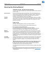
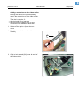
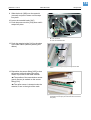
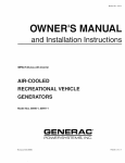
03/08 Rev. 4.04-01
USER MANUAL
AP 7.t
Setup Printer
Material Inserting Procedure ......................... 2
Selecting the Printing Material ...................... 4
Thermal transfer / direct thermal printing .. 4
Label stock ................................................ 4
Thermal transfer ribbon ............................. 5
Inserting the Label Material ........................... 6
Preparing the printer ................................. 6
Inserting the roll material ........................... 9
Inserting the Ribbon ....................................11
Exchanging mounted ribbon rolls ............12
Adjusting the ribbon tautness ..................13
When the Roll is Empty ...............................14
Material end .............................................14
Ribbon end ..............................................14
Index ............................................................15
2
03/08 Rev. 4.04-01
USER MANUAL
Setup Printer
AP 7.t
Material Inserting Procedure
CAUTION! - Trained staff is required for inserting and changing ribbons and
material!
•
•
Ribbon winding direction depicted in [1] and [2]: Colour side inwards.
Ribbon rolls with the colour side facing outwards can also be used (see [3]).
P Winding setup see section Ribbon with the colour side facing outwards on
page 3.
Material print
surface outside
1
13
[1]
12
11
3
2
10
9
4
5
6
7
8
Material and ribbon path in the AP 7.t when using textile material. Winding direction: Print
surface outside.
No. Operating Parts
No. Operating Parts
1
Ribbon rewinding mandrel
8
Material brake
2
Ribbon unwinding mandrel
9
Material guide
3
Printhead pressure lever
10
Sensor fitting
4
Material deflection axle
11
Printhead
5
Material pressure brush
12
Print roller
6
Material guide plate
13
Opener for pressure roller
7
Material roll
[Table 1] Operating parts in the AP 7.t.
3
03/08 Rev. 4.04-01
USER MANUAL
Setup Printer
AP 7.t
Print surface
inside
[2]
Material and ribbon path in the AP 7.t when using textile material. Winding direction: Print
surface inside.
[3]
Material and ribbon path in the AP 7.t when using textile material and ribbon with the
winding direction “Colour side outwards”.
Ribbon with the
colour side
facing outwards
4
03/08 Rev. 4.04-01
USER MANUAL
Setup Printer
AP 7.t
Selecting the Printing Material
Thermal transfer / direct thermal printing
The AP 7.t can print onto label stock using the direct thermal mode or thermal
transfer mode.
Direct thermal
Direct thermal printing is done without ribbon. The direct thermal process
requires label material with a temperature-sensitive coating. The printout is
produced by applying precise bursts of heat to the material under the
printhead. This changes the colour of the coating.
Thermal
transfer
Thermal transfer printing is done with (thermal transfer) ribbon on “normal”
label material. The printout is produced by applying precise bursts of heat to
the thermal transfer ribbon under the printhead. This transfers the colour
particles to the label.
Label stock
The AP 7.t was designed for printing onto textile materials.
Pay attention to the following factors when selecting label stock:
•
•
•
The roughness of the material surface.
The printhead temperature required for the colour transfer.
Size of the material roll. The following dimensions need to be checked:
Outside-/inside diameter of the material roll and the material width.
Material
roughness
If the material is very rough, the printhead will be worn down more quickly
than when using a smooth material. This is an important aspect of thermal
printing. With thermal transfer printing, this doesn’t pose such a problem,
because you can – and indeed should – select a ribbon that is wider than the
material. This means that the printhead is protected over the entire width of
the material.
Printhead
temperature
High printhead temperatures can similarly cause problems. The material and
the ribbon take longer to cool. As a result, the print quality may degrade –
particularly at high print speeds. The printhead also wears down more
quickly.
¯ The printing result very much depends on the right combination of label
material and thermal transfer ribbon. The surface of the label material
determines which thermal transfer ribbons produce the best adhesion.
Unsuitable ribbons often cause bad printing results.
Recommended textile materials include Avery Dennison’s 6860, 9505, 6880
and 9660.
P More detailed information about grammage and material width margins and
the permissible dimensions of the label roll can be found in Technical Data,
“Label Material”.
5
03/08 Rev. 4.04-01
USER MANUAL
Setup Printer
AP 7.t
Thermal transfer ribbon
The following is recommended for thermal transfer ribbons:
•
•
•
•
The back of the ribbon should be coated so that it produces no static or
friction (Backcoating). If this isn’t the case, the printhead may be damaged by
static discharge coming off the ribbon surface.
The ribbons need to be designed for “flat head” printheads.
Ribbons should be able to handle print speeds of up to 200 mm/s (8 ips).
Size of the ribbon roll: The following dimensions need to be checked: outside/
inside diameter of the ribbon roll, ribbon width.
CAUTION! - Thermal transfer ribbons without these properties can degrade
the performance of the printer and the print quality as well as damage the
printhead!
Armor APR 5 (Avery part no. 2740-410-xxx) is a recommended ribbon type.
¯ The thermal transfer ribbon should only be slightly wider than the label
material.
– If an overly narrow ribbon is used, the border of the label material interferes
with the printhead – which wears it down more quickly.
– If an overly wide ribbon is used, there is an increased risk of creases
occurring in the ribbon. This can cause a dissatisfactory printing result.
P More detailed information about the permissible dimensions of ribbon rolls
can be found in Technical Data, “Thermal Transfer Ribbon”.
6
03/08 Rev. 4.04-01
USER MANUAL
Setup Printer
AP 7.t
Inserting the Label Material
WARNING!
Danger of rotating parts drawing items in.
« When working on the printer, do not wear loose jewellery, long sleeves,
long hair, etc.
« Close the printer cover before printing.
« Always switch off the printer before replacing the print roller or the metal
tube.
•
• During operation, the printhead can become hot.
« Care should be taken when touching the printhead!
P Information on choosing a suitable label
material can be found in section Selecting
the Printing Material on page 4.
Preparing the printer
Depending on the type and width of label
material used, you may need to make two
minor adjustments to the printer:
Selecting and mounting the appropriate
print roller
Leaving the factory, the AP 7.t is equipped
with a narrow print roller [1A]. The wide
print roller [1B] is supplied with the printer.
Mat. width
Print roller
Part no.
< 50.8 mm
narrow
A6056
> 50.8 mm
wide
A6060
[Table 1] Selecting the print roller.
A
[1]
A Narrow print roller (material width < 50.8 mm)
B Wide print roller (material width > 50.8 mm)
1. Switch off the printer. Open the front
cover.
2. Remove thumb screw [2A].
A
[2]
P Continued on the next page.
B
Printer with open front cover
A Thumb screw
7
03/08 Rev. 4.04-01
USER MANUAL
Setup Printer
AP 7.t
3. Pull out the print roller[2].
4. Fit the wide print roller. Replace the thumb
screw.
[3]
Replacing the print roller
5. Turn the knob for the printhead pressure to
the position [4B] depicted. Tool: Large
screwdriver or a suitably sized coin.
A
B
[4]
Setting knob for the printhead pressure
A Setting for the narrow print roller
B Setting for the wide print roller
8
03/08 Rev. 4.04-01
USER MANUAL
Setup Printer
AP 7.t
Adding a metal tube to the ribbon roller
Leaving the factory, the printer already
carries the metal tube on the ribbon roller.
•
•
The tube is required, if:
the label web is very narrow
the label layout contains one or more
crosslines over the whole label width.
1. Switch off the printer. Open the front
cover.
2. Push the metal tube over the ribbon
roller [5].
A
[5]
Adding the metal tube (A) to the ribbon roller.
3. Clip the lock washer [6A] over the end of
the ribbon roller.
A
[6]
A Lock washer
9
03/08 Rev. 4.04-01
USER MANUAL
Setup Printer
AP 7.t
Inserting the roll material
1. Open the front cover.
B
2. Raise the pressure roller [7A]. Press the
two green levers towards each other.
A
3. Move the braking brush upwards [7B].
C
4. Move the material brake upwards until it
snaps into place [7D].
5. Remove the guide plate [7E] from the
material dispenser.
6. Match the adapter rings [7C] to the core
diameter of the material roll and pull the
other adapter rings off the dispenser.
D
E
[7]
¯ Adapter rings for a core diameter of
AP 7.t with open front cover. The pressure roller (A),
pressure brush (B) and material brake (D) are raised.
50.8 mm can be ordered (part no.
97061-02-7).
7. Place the material roll on the dispenser.
Run the material ribbon around the
deflection axle [8C].
A
B
C
[8]
¯ The rotational direction of the roll
depends on the material winding direction
[8].
The rotational direction of the material roll and the material
path depend on the winding direction:
A Print surface outside
B Print surface inside
C Deflection axle
8. Insert the material ribbon as [9] displayed.
¯ Feed the material ribbon through the
sensor fitting [9A].
A
[9]
The remaining material path
10
03/08 Rev. 4.04-01
USER MANUAL
Setup Printer
AP 7.t
9. Slide the brush [10B] over the material
(centred) and push it down until it snaps
into place.
B
10. Lower the material brake [10C].
11. Push the pressure roller [10A] down until it
snaps into place.
A
C
D
[10] A Lock the pressure roller
B Lower the brush
C Lower the material brake
12. Push the material guide [11A] to the edge
of the label ribbon (without jamming the
ribbon).
A
[11] Pushing the material guide (A) to the edge of the label
ribbon
13. Reposition the sensor fitting [10D] so that
the sensor is directly above the reflex
marks or punches of the label material.
¯ The position of the transmission sensor
(punch sensor) is marked on the sensor
fitting [12A].
A
¯ The reflex sensor is located under the
material, 5 mm to the right of the mark.
[12] The sensor fitting is marked (A) at the position of the
transmission sensor (the print roller has been removed for
this photo)
11
03/08 Rev. 4.04-01
USER MANUAL
Setup Printer
AP 7.t
Inserting the Ribbon
WARNING!
Danger of rotating parts drawing items in.
« When working on the printer, do not wear loose jewellery, long sleeves,
long hair, etc.
« Close the printer cover before printing.
•
• During operation, the printhead can become hot.
« Care should be taken when touching the printhead!
¯ Skip this section if you are printing onto
direct thermal material.
P Information on choosing a suitable thermal
transfer ribbon can be found in section
Selecting the Printing Material on page 4.
1. Open the front cover.
2. Push the ribbon roll [13A] onto the
unwinding mandrel as far as it will go. Put
the empty ribbon core [13B] on the
rewinding mandrel.
¯ Pay attention to the winding direction of
the ribbon:
B
C
D
– Colour side inwards: Ribbon unwinds
anti-clockwise.
– Colour side outwards: Ribbon unwinds
clockwise.
3. In the following cases, push the metal tube
[13C] over the ribbon roller and secure it
with the lock washer [13D]:
– The label web is very narrow
– The label layout contains one or more
crosslines over the whole label width.
A
[13] Inserting the ribbon
A Ribbon roll (winding direction: colour side inwards)
B Empty take-up roll
C Metal tube
D Lock washer
P How to? – See section Preparing the
printer on page 6.
4. Insert the ribbon as shown [13]. Fasten the
end of the ribbon to the take-up roll.
5. Turn the rewinding mandrel anti-clockwise
several times until the ribbon runs creasefree [14].
[14] The ribbon is now inserted
12
03/08 Rev. 4.04-01
USER MANUAL
Setup Printer
AP 7.t
When all the ribbon has been used:
1. Pull the full ribbon roll off the rewinder.
2. Pull the empty ribbon core off the
dispenser and put it on the rewinding
mandrel.
3. Insert a new ribbon roll following the steps
described above.
Exchanging mounted ribbon
rolls
If you need to alternate between different
types of ribbon, you don’t need to cut the
ribbon off every time, re-insert it and fasten
it to the rewinder.
There is a simpler way:
1. Open the front cover. This raises the
printhead.
2. Pull off both ribbon rolls from the ribbon roll
mandrels. Pull the rolls off from
underneath the printhead (in a sideways
motion). [15].
[15] Pulling off both ribbon rolls at the same time…
¯ It makes sense to store frequently used
ribbons as ribbon roll pairs [16].
« To insert the ribbon roll pairs, follow the
instructions in reverse order.
[16] … and storing them as a pair.
13
03/08 Rev. 4.04-01
USER MANUAL
Setup Printer
AP 7.t
Adjusting the ribbon tautness
The braking torque of the ribbon unwind
mandrel [17B] and the ribbon roll up
mandrel [17A] can be set from the front
using the red plastic hexagonal nuts [18A]
on the ribbon mandrels. The braking torque
is increased by turning them in a clockwise
direction.
A
B
During feeding, the ribbon must run
between the mandrels evenly and without
folds over the entire length. The following
hints facilitate adjustment:
•
Ribbon is slack or has folds, or is not
wound up tightly enough on the roll-up
mandrel.
[17] A Ribbon roll up mandrel
B Ribbon unwind mandrel
« Remove caps [18B]. Increase the
unwinding/roll-up torque (Turn red hex nut
clockwise).
•
•
B
The ribbon stretches visibly or tears during
printing.
Ribbon is not transported properly.
« Remove caps [18B]. Decrease the
unwinding/roll-up torque (Turn red hex nut
counter clockwise).
A
Factory setting
Although the factory settings cover a large
range of varying ribbon widths, slight
adjustment may be necessary when using
very narrow or very wide ribbon.
[18] A Red hex nut (Cap removed)
B Cap
14
03/08 Rev. 4.04-01
USER MANUAL
AP 7.t
When the Roll is Empty
Material end
When the end of the material roll passes
the punch sensor, the following message is
shown:
Status
Material end
5002
1. Pull the material end out of the front of the
printer.
2. Insert a new material roll following the
steps described in section Inserting the
Label Material on page 6.
Ribbon end
The following message appears when the
ribbon roll is unwound, that is, the
dispenser roll mandrel ceases to turn with
the roll.
Status
Ribbon end
5008
1. Open the front cover.
2. Take out the full ribbon roll.
3. Move the empty ribbon roll from the
unwinding mandrel to the rewinding
mandrel.
4. Insert a new ribbon roll following the steps
described in section Inserting the Ribbon
on page 11.
¯ Ribbon end recognition can be turned
off as required, for example for direct
thermal printing.
« Parameter SYSTEM PARAMETER > Ribbon
autoecon.: Set to “Thermal printing”.
« Further information about the parameter
menu can be found under Info-Printouts
and Parameters.
Setup Printer
15
03/08 Rev. 4.04-01
USER MANUAL
Setup Printer
AP 7.t
Index
A
Adapter rings 9
B
Backcoating 5
Braking brush 9
C
Colour side ribbon roll 11
D
Direct thermal printing 4
H
Hex nut 13
L
Label material 4
M
Material end 14
P
Printhead pressure, adjusting knob 7
R
Red plastic hexagonal nuts 13
Ribbon end 14
Ribbon tautness, adjustment 13
T
TEX, setting the printhead pressure 7
Thermal transfer printing 4
W
Winding direction of the ribbon roll 11
Winding setup, for textile material 2