1
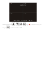
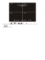
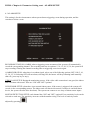
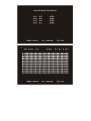
DVR Door Entry System Combo
USER MANUAL
INDEX
Chapter 1: Installation Guide
Chapter 2.1: Panel operation
Chapter 2.2: Wiring Interface
Chapter 2.3: Remote Controller
Chapter 3: Basic Operation
Chapter 4: Parameter Setting
Chapter 4: Parameter Setting cont. - Video Management Part 1
Chapter 4: Parameter Setting cont. - Video Management Part 2
Chapter 4: Parameter Setting cont. - ALARM SETUP
Chapter 4: Parameter Setting cont. - Hard drive setup
Chapter 4: Parameter Setting cont. - Miscellaneous setup
Chapter 4: Parameter Setting cont. - Network setup
Chapter 4: Parameter Setting cont – TFT Setup
Chapter 4: Parameter Setting cont. - web access
Chapter 5: Login window
Warranty
DVR with video door phone -Chapter 1: Installation Guide
Caution: Please make sure to disconnect the power supply before installation!
1.1 What is included?
While opening the box, please check:
Each component is intact without scratches and broken.
All accessories listed bellow are included:
•
•
•
•
•
•
•
•
•
•
•
1 x Monitor
1 x Outdoor camera
1 x remote controller
1 x power adaptor
1 x Monitor stand
1 x Mounting bracket
1 x User manual
1 x 15 meter outdoor camera cable (4 pins)
4 x BNC connection cable (6 pins)
1 x Alarm extension cable (5 pins)
1x Screws bag
1.2 Preparation before installation
1. Fix the mounting bracket on the wall or table before installation.
2. Please ensure for safe operation of the device with required ventilation and keep from humid
environment.
3. Make sure there is enough space for all connection cables. Cable bending radius should not be less than 5
times of the cable diameter.
1.3 Hard disk installation
1. Hard disk specification: 2.5 Inch SATA hard disk (maximum 500G).
2. How to install:
Caution: The system will automatically format the hard disk before you start recording.
DVR with video door phone -Chapter 2.1: Panel operation
2.1 Panel operation
Chart 1: Front panel keys instruction
No.
Type
1
Indicator
light
Icon
Details
Power indicator, blue light when in working mode.
Channel 1/ Number key 1: full screen display real time monitor of
channel 1.
Channel 2/ Number key 2: full screen display real time monitor of
channel 2.
2
Display
keys
Channel 3/ Number Key 3: full screen display real time monitor of
channel 3.
Channel 4/ Number Key 4: full screen display real time monitor of
channel 4.
Quad monitor: display four channels at same time.
3
Function
keys
Enter/exit key: enter/exit main menu, save settings when exit
Audio channel select: switchover audio of a channel to be played on
monitor.
Record key.: press to start recording of preset camera(s)
Stop key: stop recording/playback operation.
Play: press to play record.
Up key
Down key
4
Control
keys
Left/backward key: in playback mode, press to backward
Right/forward key: in playback mode, press to forward
Confirm key
5
Monitor/talk
key
Monitor outside or talk to visitors.
6
Unlock key
Open the door for visitors.
7
IR Receiver
window
Direct to the IR receiver when you use remote controller.
8
Microphone
When door phone is in use, talk to visitors through the microphone.
DVR with video door phone -Chapter 2.2: Wiring Interface
Chart 2: Wiring interface instruction
1
Power supply
DC 12V/14V
2
Outdoor station 2 interface Connect to outdoor station 2, 4 pin S-Terminal.
3
Outdoor station 1
interface
Connect to outdoor station 1, 4 pin S-Terminal.
4
Network interface
Connect to the internet.
5
Camera 1 interface
Connect to Camera 1, 6-pin S-Terminal.
6
Camera 2 interface
Connect to Camera 2, 6-pin S-Terminal.
7
Camera 3 interface
Connect to Camera 3, 6-pin S-Terminal.
8
Camera 4 interface
Connect to Camera 4, 6-pin S-Terminal.
9
Sensor interface
Connect to external sensor and alarm devices, 5-pin S-Terminal.
DVR with video door bell-Chapter 2.3: Remote Controller
Chart 3: Remote controller function key instruction
No.
Name
1
Menu key
Icon
Operation
Enter/exit menu
Up
2
Direction/confirm
keys
Down
Backward
Forward
Confirm
3
Audio channel
select key
4
Display keys
Switchover audio of a channel
Channle 1/number key 1
Channel 2/number key 2
Channel 3/number key 3
Channel 4/number key 4
Quad monitor
5
REC key
Record
6
Stop key
Stop
7
Monitor display
off key
Turn off monitor display
8
Monitor/talk key
Monitor / talk
9
Unlock key
10
Play key
Unlock
Play
DVR with video intercom - Chapter 3: Basic Operation
3.1 How to switch on/off
(1). Switch on
Push the power switch on the left side of the indoor unit, the monitor will start.
Note: The monitor shows quad monitoring at starup as default mode. If the time is within schedule recording
time, the system will automatically start the schedule recording function, and then the system will continue
to work properly.
(2). Switch off
Press the stop key
to turn the system in stop recording mode, and then push the power switch on
the left side of the indoor unit. The system stops running.
(3). Power failure recovery
If the DVR is in recording mode and the system power is cut or shut off, after regaining of power supply, the
DVR will automatically save the video before the power loss and automatically return to the working mode
before power loss, and then continue working.
DVR with door entry system - Chapter 4: Parameter Setting
4.1 Main menu instruction
Under the stop recording mode, push the button
shows the following screen:
either on the monitor or the remote controller, then
The following is the introduction on sub-menu functions.
4.2 Video Management
4.2.1 CAMERA SET UP
Each channel can be set separately on or off. If set to off, the corresponding screen goes black, the screen
does not display image of the channel. The corresponding video ercording function is closed. When re-open
the channel, you need to enter the camera setup to turn on the same channel before recording, as shown in
bellow picture:
Method: push the button
then, push
、
、
or
to set the channel "ON" or "OFF".
, to put
to the channel to be set, and
DVR8 - Chapter 4: Parameter Setting cont. - Video Management Part 1
4.2.2 RECORDING SETUP
Each channel can be set separately to record video or not, if it is set to "OFF", thescreen will continue to
show channel pictures, but not for recording.
Method: push the button
push
、
、
or
, to put
to the channel to be set, and then,
to set the channel "ON" or "OFF". There are three options: "OPEN","OFF", " CAM".
4.2.3 RECORDING FRAMETRATE
Frame rate of each channel can be separately set 1,2,3,4,5,6,7,8,9,12,16,25 FPS / sec. For PAL system, the total frame rate is 50
FPS; for NTSC system, 60 PFS. In the case of PAL system, the average per channel is 12PFS. If a particular channel’s frame rate
is set to more than 12PFS, the additional frame rate needs to be borrowed from other channels.
Method: push the button
push
to set the channel.
、
、
or
, to put
to the channel to be set, and then,
DVR8 - Chapter 4: Parameter Setting cont. - Video Management Part 2
4.2.4 VIDEO QUALITY
The setting of video recording quality has 3 selections: "HIGH", "NORMAL" and "LOW".The higher
grades, the better video recording quality, also with the bigger capacity of video file occuping the hard disk
space.
Method: push the button
push
、
or
, to put
to the time period, and then,
, to put
to the channel to be set, and
to set the recording mode during this period.
Method: push the button
then, push
、
、
、
or
to set the required video quality.
4.2.5 RECORDING SCHEDULE
The "RECORDING SCHEDULE" has 3 options: "NO RECORDING", "RECORDING" and "ALARM
RECORDING". It can be set to each hour in 24 hours.
NO RECORDING: Set to this mode will not record;
RECORDING: Set to this mode will record normally;
ALARM RECORDING: This mode for motion detection recording and alarm recording.
DVR8 - Chapter 4: Parameter Setting cont. - ALARM SETUP
4.3 ALARM SETUP
This setting is for the circumstances when system detects triggering events during operation, and the
reactions to thiese events.
RECORDING TIME ON ALARM: when a triggering event encountered, the system will automatically
record the corresponding channel. The recording time has six options: 5, 10, 15, 20, 25, 30, the system will
stop recording if during the channel recording time no triggering event occurs again.
ALARM DURATION: when there is an alarm signal, select one of the following options (OFF, ON) 5, 10,
15, 20, 25, 30. Selecting OFF will not alarm; selecting ON, the buzzer will keep alarming until manually
shut off ( press any key to stop);
VIDEO LOSS SETUP: During the monitoring process, if the video cable connection is not good, the indoor
unit will alarm with sound. There are "ON" and "OFF" optional.
H/W SENSOR SETUP: when there is an external alarm sensor, if the sensor is triggered, the system will
record via the corresponding camera. The indoor unit will alarm with sound (if connect to externall alarm
device, the system can also drive the alarm). The system can connect to two ways of alarm sensor inputs.
MOTION DETECTION SETUP: each channel has "ON" and "OFF" optional. Four sensitivity levels can be
selected on each area. The sensitivity increases with the number rising. The level of sensivity can be
adjusted by pressing
.
DVR8 - Chapter 4: Parameter Setting cont. - Hard drive setup
4.4 Hard drive setup
This menu includes: overwriting, hard disk information and formatting settings.
OVERWRITE ENABLED: When set to 【YES】, if disk storage is full, it will automatically overwriter.
ST9408221AS: The current information of hard disk.
MASTER HDD SIZE: The capacity of current hard disk.
MASTER HDD USED: the occupation of hard disk space, displayed in percentage.
MASTER HDD FORMAT: Format the current hard disk; the system default password is 111111 (press
6 times)
DVR8 - Chapter 4: Parameter Setting cont. - Miscellaneous setup
4.5 Miscellaneous setup
This will set system-related issues, including PASSWORD SETTING, SET TIME, HIDDEN CHANNEL,
AUDIO PORT SETUP, MUSIC SELECT, LANGUAGE and USE PASSWORD LOGIN, etc.
PASSWORD SETTING: system password can be set,
for 3,
stands for 1,
stands for 4. The system default password is 111111. (press
stands for 2,
six times).
stands
Method:move
to the "PASSWORD SETTING" ,and then push
to enter sub-menu. Input old
password (default is 111111), and then input "NEW PASSWORD" and "CONFIRM NEW PASSWORD". If
input error, press
to delete.
TIME: Set the system time.
Methods: press
or
to move
to the digit you want to adjust, and then press
to
change the numbers.
HIDDEN CHANNEL: To set a certain channel to be shown on the screen or not. However, under the
recording mode, the hidden channel can still be recorded. There are 5 options: "OFF", "1", "2", "3" and "4"
AUDIO PORT SETUP: 2 ways of audio ports can be set. Setting the RECROING OFF can select for audio
to be recorded or not.
For example: All the four cameras have audio input. Now need to set channel 1 and channel 3 to save the
audio around.
Methods:Move
to "Audio Port 1", then press
down to next line
Set "AUDIO RECORDING" to "YES".
Move
to "Audio Port 2", then press
next line
Set "AUDIO RECORDING" to "YES".
Setting finished..
to select channel 1. Press
to select channel 3. Press
to move
to move
down to
MUSIC SELECT: This will set the ringing melody of the indoor unit when calling from outdoor station.
There are total 9 options, of which 00 is silent.
LANGUAGE: The default languages are Chinese and English.
USE PASSWORD LOGIN: Default setting is "OFF"
DVR8 - Chapter 4: Parameter Setting cont. - Network setup
4.6 Network setup
NETWORK SETUP
1) Press [menu] on the remote controller to enter into the main menu
Use arrow keys (▲) and (▼) to select "NETWORK SETUP" menu, press [OK] to confirm, and enter into
the "NETWORK SETUP" screen.
IP Type: Support two kinds of IP, DHCP (dynamic) and STATIC (static), if DHCP is enabled then IP
address will be obtained through the DHCP server automatically. If selecting STATIC, then you will need to
manually set IP address, subnet mask, and gateway.
IP ADDRESS: Setting IP address
Using the keys (▲) and (▼) to select the numbers, left and right keys to select the digit you need to set up,
press [OK] button to confirm. Then press [Menu] to save and exit.
SUBNET MASK: Set the subnet mask
GATEWAY: Set the gateway
DNS ADDRESS1: DNS address1 setting
DNS ADDRESS2: DNS address2 setting
HTTP PORT: Setting protocol port for network acess, the default value is 80, changeable
1024-49151.
USER SETUP: there are 2 types of user IDs provided for network access, one is "ADMIN ID", with full
operating rights; the other is "USER ID", whose right is only preview the image.
DDNS SETUP: To set up Dynamic Domain Name Service. You will need to register from the DDNS ISP
service provider, and then set according to the registration information.
Note: All the IP address, subnet mask, gateway, DNS1 can be obtained from the computer(connected to the
same router) by typing "ipconfig /all" in the command line.
DVR8 - Chapter 4: Parameter Setting cont – TFT Setup
4.7 TFT setup
The three options: BRIGHTNESS SET UP, CONTRAST SET UP AND SATURATION SET UP can be
adjusted, in which each of the adjustable range is from 0 to 30.
4.8 Reset menu
Input DVR system password, to reset all settings to factory default except for the network setup and system
password. The default password is press111111 (i.e. press
six times).
Player software
The format of saved files is .MCG and requires special software to play. Explore the CD attached with the
product; open the software
How to operate?
to play the saved files.
DVR8 - Chapter 4: Parameter Setting cont. - web access
1. Opening port
This is to open web access port from the router. Opening port on different types of routers will be in
different ways. For a specific router, please contact the vendor to get details. Here is an example to open
ports on a TP-Link router:
3. IE ACCESS: after opening port, open an IE browser process, select "Tools" - "Internet Options" "Security" - "Internet" - "Custom Level". In the popup window, open all the ActiveX plug-ins and controls.
After opening ActiveX controls, refresh IE browser and enter the access address in the Address bar:
http://IP: [port] to visit SVR host, as shown bellow:
Note:
a. You can access directly via LAN address if in LAN. WAN IP is needed for WAN access. The port
number can be omitted when using the default port 80, for example: http://192.168.18.101
b. First visit will be prompted to install plug-in, select "Yes" to install it.
DVR with video door entry - Chapter 5: Login window
λ Connected: Display system connection status
λ Capture tools: Control the image capture and recording functions.
λ Remote DVR Control Panel : DVR Control
Connected: Displays the current connection status and the data transfer rate.
Capture tools: image capture and video stream capture through functions on the left, and then store on the
PC.
The left side's functions.
DVR with video door entry - Chapter 5: IE Configuration
5.1 Configure and install IE
Note: you must configure IE security settings before remote viewing, detailed steps are as follows:
Right click the "Internet explorer" icon on windows desktop, in pop-up menu; select "Properties" to enter the
Internet Options window as shown below:
1) Click on the Custom Level button, entering the Security Settings window to download unsigned Active X
controls
2) Click the OK button to finish the IE security settings
3) After IE security is configured, you can now monitor from remote through IE.
5.2 IE operation
1) Open an IE browser, input the indoor unit's IP address, and then download plug-ins in the pop-up page.
Installation will begin automatically after downloading. If the plug-ins does not beging to download
automatically, please click "Download" in "If the plugin can not download, click here", when the download
is finished, double click to installation.
2) After the plug-in installation, it will pop up the following screen. If not, plese close and restart IE then
input the network address correctly.
Click
, then appears the user name input box as the left picture, enter the user name and password:
user name and password are considered as ADMIN.
Note: The user name and password are all capital letters.
Click
to enlarge 2 times for the preview screen.
WARRANTY CARD
NB Please keep this document safe, as it is proof of your Warranty
Your Video door system comes with a one year Manufacturers Warranty. When
used normally, the following services are offered:
1. Replacement for malfunctioning parts in first three months
2. Repair free of charge for malfunctioning parts in first year
The following actions will void the Warranty:
1. Damage to the device during installation
2. Damage to the device through misuse
3. Opening and/or disassembling the device
4. Attempting to force the device to perform functions for which it
is not intended
5. Attaching the device to power supplies other than those
recommended by the manufacturer
Distributor for Warranty purposes:
Intelligent Home Online Ltd
34a High Street
Hornsey
London
N8 7NX
+44 (0)20 83482040
www.intelligenthomeonline.com
www.laletrading.com
Product: ______________________________________________
Purchaser Name: _______________________________________
Invoice N: _____________________________________________
Purchase Date_____________________________________________