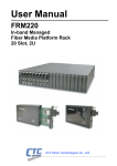
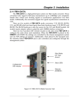
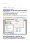
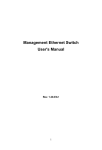
Download FRM401 USER MANUAL - Datainterfaces.com
Transcript
USER MANUAL FRM401 Fiber Media Converter Rack Type, 48-Port, 4U The information contained in this document is subject to change without prior notice. TRADEMARKS Ethernet is a registered trademark of Xerox Corp. ST® is a registered trademark of AT&T. Windows® is a registered trademark of Microsoft Corporation WARNING: This equipment has been tested and found to comply with the limits for a Class A digital device, pursuant to Part 15 of the FCC Rules. These limits are designed to provide reasonable protection against harmful interference when the equipment is operated in a commercial environment. This equipment generates, uses, and can radiate radio frequency energy and if not installed and used in accordance with the instruction manual may cause harmful interference in which case the user will be required to correct the interference at his own expense. NOTICE: (1) The changes or modifications not expressively approved by the party responsible for compliance could void the user's authority to operate the equipment. (2) Shielded interface cables and AC power cord, if any, must be used in order to comply with the emission limits. CISPR PUB.22 Class A COMPLIANCE: This device complies with EMC directive of the European Community and meets or exceeds the following technical standard. EN 55022 - Limits and Methods of Measurement of Radio Interference Characteristics of Information Technology Equipment. This device complies with CISPR Class A. WARNING: This is a Class A product. In a domestic environment this product may cause radio interference in which case the user may be required to take adequate measures. CE NOTICE Marking by the symbol CE indicates compliance of this equipment to the EMC directive of the European Community. Such marking is indicative that this equipment meets or exceeds the following technical standards: EN 55022:1994/A1:1995/A2:1997 Class A and EN61000-3-2:1995, EN61000-3-3:1995 and EN50082-1:1997 CTC Union Technologies Co., Ltd. Far Eastern Vienna Technology Center (NeiHu Technology Park) 8F, No. 60, ZhouZi St. NeiHu, Taipei, 114 Taiwan Phone: +886-2-2659-1021 FAX: +886-2-2799-1355 FRM401 Installation and Operation Manual Fiber Media Converter Rack Mount This manual supports the following models: FRM401 Version 2.0 released October 2004 This document is the second officially released manual. Please check CTC Union's website for any updated manual or contact us by E-mail at [email protected]. Please address any comments for improving this manual or to point out omissions or errors to [email protected]. Thank you. The information and specifications in this document are subject to change without notice. Table of Contents Chapter 1. Introduction 1.2 Functional Description............................................................................................................ 1-2 1.3 Specifications.......................................................................................................................... 1-3 1.4 Front & Rear Panel Description.............................................................................................. 1-5 Chapter 2. Installation 2.1 General.................................................................................................................................... 2-1 2.2 Site Preparation....................................................................................................................... 2-1 2.3 Mechanical Assembly............................................................................................................. 2-1 2.4 Electrical Installation .............................................................................................................. 2-2 2.5 Power Supply Modules ........................................................................................................... 2-3 Chapter 3. Converter Cards 3.1 Overview ................................................................................................................................ 3-1 3.2 Overview for FRM401 card..................................................................................................... 3-2 3.3 Status LEDs ............................................................................................................................. 3-3 3.4 Optical Transceiver Specifications ......................................................................................... 3-4 Chapter 4. Management 4.1. Introduction............................................................................................................................ 4-1 4.2 Overview of FRM401-SNMP Card ........................................................................................ 4-2 4.3 Hardware Installation Procedures ........................................................................................... 4-3 4.4 Terminal Mode........................................................................................................................ 4-4 4.11 Menu System Detail.......................................................................................................... 4-6 4.12 SNMP Card TCP/IP configuration.................................................................................. 4-11 4.13 SNMP Card Manager configuration. .............................................................................. 4-12 4.5 MIBs for Standard SNMP Platform...................................................................................... 4-13 Chapter 5. GUI Installation and Operation 5.1 GUI SNMP Manager Features................................................................................................ 5-1 5.11 Monitor and get the status of FRM301/401 ...................................................................... 5-1 5.12 Set the configuration of FRM301/401 .............................................................................. 5-1 5.13 Other miscellaneous features ............................................................................................ 5-1 5.2 User System Requirements ..................................................................................................... 5-2 5.3 Client IP Setting...................................................................................................................... 5-3 5.4 Software Installation and Removal.......................................................................................... 5-8 5.41 Introduction ....................................................................................................................... 5-8 5.42 System Requirements........................................................................................................ 5-8 5.43 Installation......................................................................................................................... 5-8 5.44 Remove GUIMGR .......................................................................................................... 5-10 5.5. SNMP Card Configuration ................................................................................................... 5-12 5.51 Introduction ..................................................................................................................... 5-12 5.52 HyperTerminal™ settings ............................................................................................... 5-12 5.53 Connecting to the FRM301/401...................................................................................... 5-12 5.54 FRM301/401 menu system ............................................................................................. 5-13 5.55 SNMP Card settings........................................................................................................ 5-14 5.6. GUIMGR Configuration and Operation ............................................................................... 5-18 5.61 Introduction ..................................................................................................................... 5-18 5.62 Configuration .................................................................................................................. 5-18 5.63 Operation......................................................................................................................... 5-21 Table of Contents Chapter 5. GUI Installation and Operation (continued) 5.7 Troubleshooting ..................................................................................................................... 5-27 5.71 Network Settings............................................................................................................. 5-27 Appendix A. A.1 Alarm Messages.................................................................................................................... A-1 A.2 Trouble Shooting................................................................................................................... A-2 Appendix B. B.1 FRM401 Cards (Spec.)...........................................................................................................B-1 B.2 FRM401-10 Card ...................................................................................................................B-2 B.3 FRM401-100 Card .................................................................................................................B-3 B.4 FRM401-10/100 Card ............................................................................................................B-4 B.5 FRM401-10/100W (WDM) Card...........................................................................................B-5 B.6 Version Compatibility ............................................................................................................B-6 Appendix C. C.1 FRM401 SNMP Upgrade Procedure......................................................................................C-1 C.11 Preconditions ...................................................................................................................C-1 C.12 Items Required.................................................................................................................C-1 C.2 Equipment Setup .....................................................................................................................C-1 Chapter 1 Introduction 1.1 General The FRM401 is a 4U high 19" Rack, 12 slot modular media converter center that provides an economic solution in high density Fiber Converter installations such as central offices. The Power Modules are designed for redundant power supply operation. Power and line cards are all "hot" swappable. An additional feature allows the FRM401 to detect the working or failing status either of power module or any fan assembly in the unit. There are 12 slots available for installation of FRM401- 10/100 Series Line Cards in the FRM401 compact rack. An optional SNMP Card may be installed next to the power card, for local and remote management purposes. Each FRM401 Line Card contains four independent fiber to Ethernet converters. A variety of cards are available that support multi-mode or single-mode fiber types and connections to SC, ST, LC or MT-RJ or even the latest WDM (Wave Division Multiplexing) in ranges from 2KM to 120KM. Figure 1-1 Solution for FRM401 Series Application 1-1 Chapter 1 Introduction 1.2 Functional Description The FRM401 optionally incorporates an additional Power Supply Module. The modules, depending on the model, derive their power from either an AC power source (110VAC or 220VAC) or DC (-42 to -60VDC) power source. When two modules are installed, they provide for power redundancy and are hot swappable even during the FRM401 Line Cards' transmissions. The FRM401 provides all Ethernet interface connections (RJ-45) on the rear of the FRM401 Chassis. The fiber interface connectors are also located on the individual FRM401 Line Card's face, along with status indicator LEDs and any required control switches. The status LED indicators provide for quick indications of both Ethernet and fiber link statuses. The FRM401 and FRM401 Line Cards fully meet all Ethernet specifications including IEEE802.3(10Base-T) and IEEE802.3u(100Base-TX). When the FRM401 is ordered with an optional SNMP Card, the card is placed next to the power modules. Control is accomplished either via local control on the asynchronous RS-232 port with an ASCII terminal or via Ethernet and Telnet terminal or any standard SNMP network management software that supports MIB-II. The SNMP GUI Windows® based program provides an easy method for the user to operate and monitor many systems. 1-2 Chapter 1 Introduction 1.3 Specifications Complied Standards IEEE802.3 10Base-T, IEEE802.3u 100Base-TX, 100Base-FX 10/100Base RJ-45 Connectors All Ethernet connections are located on the rear panel of the FRM401 Chassis. One RJ-45 connector is provided for each interface converter. All connections are designed as MDI type, requiring only a straight connection to a HUB device. Connections to non-HUB devices such a NIC (Network Interface Cards) require the use of crossover UTP cables. RJ-45 Type RJ-45 Jack ID MDI (to HUB) RJ-45 Pin 1 2 3 6 MDI-X type MDI type Rx+ Tx+ RxTxTx+ Rx+ TxRx- 10Base-T UTP Cable Requirement Cable type: Category 3, 4 or 5. Maximum cable distance: 100 meters (328 feet) 100Base-TX UTP Cable Requirement Cable type: Category 5. Maximum cable distance: 100 meters (328 feet) 1) Fiber Optic Connectors Fiber access connectors are provided for fiber optic cable connection on each card. Each connector has labeling for "Tx" (for transmission of optical data) and "Rx" (for reception of optical data). FRM401 Line Card options (all converter interfaces per card are identical) 10/100 Base Media Converter Line Card Specification Card Type Fiber Mode Wave Length Connector Fiber Cable*1 Max. Length*2 MDI 10/100M/2 Multi 1310nm ST or SC 62.5/125µm 2Km Fixed 10/100S/15 Single 1310nm ST or SC 9/125µm 15Km Fixed 10/100S/30 Single 1310nm ST or SC 9/125µm 30Km Fixed 10/100S/50 Single 1310nm ST or SC 9/125µm 50Km Fixed 10/100S/120 Single 1550nm ST or SC 9/125µm 120Km Fixed TP Ports Shielded RJ-45 jacks Cable Please refer the spec. above Environment Temperature : 0~50°C Relative Humidity : 10%~90% non-condensing Dimension : 17.7x25.5x2.4cm 10/100 Base WDM (Bi-directional) Media Converter Line Card Specification Card Type Fiber Mode Wave Length Connector Fiber Cable*1 Max. Length*2 MDI 10/100W/20A Single 1310/1550nm SC (WDM) 9/125µm 20Km Fixed 10/100W/20B Single 1550/1310nm SC (WDM) 9/125µm 20Km Fixed 10/100W40A Single 1310/1550nm SC (WDM) 9/125µm 40Km Fixed 10/100W40B Single 1550/1310nm SC (WDM) 9/125µm 40Km Fixed **Specifications are subject to change and modify without notice. **FRM401 line cards are compatible for use with FRM501 chassis. 1-3 TP Ports Shielded RJ-45 jacks Cable Please refer the spec. above Environment Temperature : 0~50°C Relative Humidity 10%~90% non-condensing Dimension : 17.7x27.5x2.4cm Chapter 1 Introduction Environment Temperature Humidity 0 - 50oC(Operating); 0 - 70oC(Storage) 20-80% non-condensing (Operating) 10-90% non-condensing (Storage) Alarm relay contact ratings 125VAC 110VDC 30VDC 1A 0.6A 4A Power Module Specification AC Power Module Input : Output : Manual Jumper 110VAC or 220 VAC; Frequency : 50~60 Hz DC 48V, 8.5A DC Power Module Input : Output : -42~-60 VDC DC 48V, 8.5A Dimension 438mm (Width) x 285mm (Depth) x 180mm (Height) Net Shipping Weight Approximate : 11.7lbs (5.3kgs) 1-4 Chapter 1 Introduction 1.4 Front & Rear Panel Description Hot Swappable Power Modules (AC Type Shown) Craft Port (Asynchronous RS-232 DCE) SNMP Card (Optional) FRM Converter Cards (10/100FX-WDM in slots 1-2, 10/100FX-SC in slots 3-12) 10/100Base-TX (SNMP over Ethernet) Four(4) Converters per card (completely independent) Figure 1-2 Front Panel of FRM401 1-5 Chapter 1 Introduction Cooling Fan Assemblies 12 x 4 Shielded RJ-45 for 10Base-T, 100Base-TX, or 10/100(auto) (depending on Line Card) Alarm Relay Terminals Mains Switch Figure 1-3 Rear Panel of FRM401 1-6 IEC AC Mains Input Chapter 2 Installation 2.1 General This chapter explains in detail the requirements and procedures for the installation of the FRM401 Rack Mount Series Fiber Converter Concentrator. 2.2 Site Preparation Install the FRM401 within reach of an easily accessible grounded AC outlet. The outlet should be capable of furnishing 90 to 250 VAC. Refer to 2.4 Electrical Installation. Allow at least 10cm (4 inch) clearance at the front of the FRM401 for the power cables. DC model is designed to accept central office -48VDC. 2.3 Mechanical Assembly The FRM401 is designed for rack mount installation and will require 4U space in a standard EIA 19" or 23" telecom rack. For the FRM401, there are five fan units in the rear side of the chassis. Without operation fans, excessive temperatures within the unit might cause it to electrically shutdown. The FRM401 chassis is delivered completely assembled, however converter cards may or may not be installed in the chassis upon delivery. The rack mount "ears" may be placed along the front or centrally located on the chassis and support both 19" and 23" mounting. Figure 2-1 Rack-Mount Installation of FRM401 Unit 2-1 Chapter 2 Installation 2.4 Electrical Installation In the AC model, AC power is supplied to the FRM401 through a standard IEC 3-prong receptacle, located on the rear of the chassis. In the DC model, DC –48V is connected to the lower terminal block, observing the proper polarity. The FRM401 should always be grounded through the protective earth lead of the power cable in AC installations, or via the ground connection for DC installations. -48V RTN FG Right: Live line Left: Neutral line Middle: Ground Left: 48V Negative Middle: 48V Positive Right: Frame ground The alarm relay provides one set of Power Failure (normally open) & FAN Failure (normally open) contacts for monitoring the power and fans condition of the FRM401. NO NC Common Alarm Relay Terminals Figure 2-3 Alarm Relay Terminals 2-2 Chapter 2 Installation 2.5 Power Supply Modules The Power Supply Modules in the FRM401 are available in two versions, AC or DC. The AC version supports selectable input voltages of 110 or 220 volts at frequencies of 47 to 63 Hertz. The DC version supports -42 to –60 VDC input voltage. Only one power supply module is required to power a completely full rack. When two Power Supply Modules are installed, the supplies share the load and are hot swappable, meaning any one supply may be removed and replaced without impacting the operation of the FRM401 Rack. It is very important that the jumper on the AC power module be set to the proper setting for the input voltage, either 110VAC or 220VAC. Confirm the jumper setting by pulling out the power module and physically confirming the setting for power in your area. Mains Switch in back Line Fuse Holder Location Line Voltage Selection Jumper (AC only) 110V 110V 220V 220V Select 110V Figure 2-4 Power Modules for FRM401 2-3 Power Module (one or two) Select 220V Chapter 2 Installation This page left blank intentionally 2-4 Chapter 3 Converter Cards 3.1 Overview (** Line cards from the FRM501 series may also be installed into the FRM401 chassis. Please refer to Appendix B.) The Converter Modules for the FRM401 are Media Converter Line Cards which slide into the FRM401 chassis, and interface with the pack panel "main board". The back panel provides an interface connection to the converter cards for Ethernet connection. The cards are designed to be "hot" swappable, meaning the FRM401 chassis need not be powered off in order to replace a card. Each converter card has a protection fuse and its own on card DC regulator to derive the required operating voltage. Removal and installation of converter cards with the rack chassis under power will not effect the operation of other converter cards, and will only cause an alarm record in the GUI program and SNMP Terminal Mode (SNMP option installed). Removal of a converter card is accomplished by loosening the two (2) captive screws on the upper and lower metal cover of the card, and then pulling the cover straight out of the chassis with the same screws. Apply equal pulling force to both top and bottom captive screws to avoid the card binding in the rails of the chassis. Replace the card by reversing the procedure, align in the slot groove and gently seat the card, retightening the captive screws. Card Rail Fiber Optic Interface Connectors Full/Half, Duplex (Fiber) Captive Screws Line Card #1 Line Card #12 Figure 3-1 Installation/Removal of FRM401 Line Cards 3-1 Chapter 3 Converter Cards 3.2 Overview for FRM401 card Fiber Optical Interface Connections Status LEDs Full/Half Fiber Duplex Selector Switch CPU Power Protection Fuse DC-Power Supply Interface Connector Figure 3-3 Side-view of FRM401 Converter Card 3-2 Chapter 3 Converter Cards 3.3 Status LEDs Figure 3-4 LEDs for FRM401 Series Line Card LED FX LINK Function Fiber link UTP LINK Ethernet link LAN 100 mode display LAN Full mode display State On Off Blinking On Off Blinking On Off On Off Status The fiber link is ok. No link or the link is faulty. Receiving data on the fiber. The UTP link is ok. No link or the link is faulty. Receiving data on Ethernet. UTP side is operating in 100M mode. UTP side is operating in 10M mode UTP side full duplex mode (200m). UTP side half-duplex mode 3-3 Chapter 3 Converter Cards 3.4 Optical Transceiver Specifications Type Distance (Km) Distance (miles) Wavelength (nm) BER Sensitivity Output Power Power Margin Return Loss ST Conn. SC Type LC MT-RJ FC M-M 2 Standard Types S-M S-M S-M 15 30 50 S-M 120 1.25 10 20 30 75 1310 1310 1310 1310 1550 -10 -10 -10 -10 12 12 25 25 Tx:1310 Tx:1550 Tx:1310 Tx:1550 Rx:1550 Rx:1310 Rx:1550 Rx:1310 -10 -10 -10 <10 <10 <10 <10 <10 <10 <10 <10 <10-10 -31dBm -32dBm -35dBm -36dBm -35dBm -32dBm -32dBm -32dBm -32dBm -20dBm -20dBm -15dBm -8dBm 0dBm -18dBm -15dBm -10dBm -7dBm 11dB 12dB 20dB 28dB 35dB 14dB 17dB 22dB 25dB -12dBm -12dBm -12dBm -12dBm -12dBm -14dBm -14dBm -14dBm -14dBm v v v v v v v v v v v v v v v v v v v v v v v v v v v v v M-M: multi-mode S-M: single-mode * For WDM, 'A' type must be paired with a 'B' type. 3-4 -10 WDM Types* S-M S-M S-M S-M 20(A)* 20(B)* 40(A)* 40(B)* Chapter 4 Management 4.1. Introduction There are three management / configuration modes for the FRM series when the SNMP optional management card is installed in the chassis. First, an asynchronous RS-232 port on a DB9 female connector provides a DCE communication port that may be accessed by terminal emulation programs such as Windows® HyperTerminal™. Second, the same terminal mode menu is available via TCP/IP Telnet connection, once the SNMP card has been configured for network operations. Lastly, the SNMP card provides an interface via TCP/IP for the SNMP protocol. Simple Network Management Protocol is a network managing standard that allows the FRM to be managed from any network management software when compiled with our provided MIB (Management Information Base) file. A Windows® based GUI (Graphical User Interface) program is supplied that also allows remote configuration and monitoring of the FRM, using SNMP protocol. The GUI SNMP Manager was developed to provide automatic device discovery, network topology, browse events, browse alerts, fault management, real-time monitoring, configuring, and reporting features. The latest version SNMP card even provides for remote flash BIOS update via TFTP. Figure 4-1 LAN Application 4-1 Chapter 4 Management 4.2 Overview of FRM401-SNMP Card SNMP Card Figure 4-2 Overview for Assembling FRM401-SNMP PWR LED –Indicate the power status Console Port –Connection for the terminal PC (RS-232 Async DCE) 10/100BASE-TX –Connection for Ethernet (SNMP over Ethernet) LINK LED – Light in yellow when the Ethernet connection is linked SNMP LED – Light in green and flash when the SNMP card has booted Figure 4-3 SNMP Card Front Panel on FRM401 4-2 Chapter 4 Management 4.3 Hardware Installation Procedures Required tools and supplies : Small, flat blade screwdriver (to aid if the thumb screws are too tight and in removal of EEPROMs from the line cards), you may see the over-view graphic drawings for the FRM301 & FRM401. Those drawings will give you the better idea how to assemble the unit. Procedure 1. Inspect the contents of the FRM401 SNMP kit. It should contain one(1) SNMP card, one(1) MIB file floppy diskette or CDROM, and possibly CPUs for updating the converter line cards. 2. The installation of the FRM401 SNMP feature card may be performed while the FRM401 unit is fully powered. However, to avoid excessive network down time, the entire unit should be removed from service. Carefully slide the FRM401 SNMP Card into the rack case from the rear side until fully seated and tighten the captive thumb-screws. 3. Refer to the connectors on the SNMP card. The DB9 Female connector labeled "RS-232" is for connection to a standard terminal device or PC running a terminal emulation program such as HyperTerminal™. Connection to the PC's RS-232 DTE is via a standard 9 pin serial pin-to-pin cable. (Only the TX, RX, and SG need be connected.) 4. While still referring to SNMP card's face, the RJ-45 connector, labeled "LAN", is for a direct Ethernet connection to a HUB device. The Ethernet port provides the connection to the network on which the SNMP management workstation is located. Two LEDs are located directly below the Ethernet connector, one labeled "LINK", the other labeled "SNMP". The "LINK" LED will be lit when a proper Ethernet connection has been established. The "SNMP" LED will flash green once per second when the FRM401 SNMP card has fully booted and is operational. 4-3 Chapter 4 Management 4.4 Terminal Mode Control Port General The FRM401 SNMP Terminal Port, labeled RS-232 on the card face, is an RS-232 asynchronous console terminal port designed to facilitate monitoring the condition of all converter cards and links as well as setup of all SNMP parameters through the use of a standard text based terminal or any terminal emulation program running on a Personal Computer. Terminal Connection A notebook computer has become an invaluable tool of the Systems Engineer. Connection to the computer is very simple. The FRM401 SNMP acts as a DCE to the PC's DTE communications port. The only hardware required is a DB9-pin one-to-one, male to female cable. A convenient application, provided with the Microsoft Windows 9X or NT® operating systems, is "HyperTerminal ™". To Start the Hyper-terminal, following the steps below: Please follow the instruction to connect the terminal mode 1. Start "Hyper-terminal" program -On Windows 98 or Windows NT: start Tool Bar Æ Program Æ Accessory Æ Hyper Terminal Group Æ Double Click Hypertrm.exe Æ Enter Connection Name Select Icon Æ Click OK 2. Select COM port to communicate with SNMP Card Choose direct to COM1 or COM2 Æ click OK 3. Set Port Properties -Port Setting: Bit per second: 38400 Data bits: 8 Stop bits: 1 Parity bits: None Flow Control: None NOTE : Make the appropriate connections between the SNMP card and the COM port, apply power to the FRM401 , then press SPACE or ENTER after SNMP card is fully booted. A fully booted SNMP card is indicated when the front panel SNMP LED is in a steadily flashing, once per second, state. You may then use the "Terminal Mode" to access the FRM401. Once the SNMP configuration has been set, including the IP address, the SNMP card may be connected to Ethernet and accessed with Telnet, SNMP or TFTP TCP/IP protocols. Configuration steps are explained later in the manual. 4-4 Chapter 4 Management The FRM401 rack SNMP LAN port can be remote controlled by a Telnet application. There is a Telnet application which can be opened in NT's command prompt and connects to the specific FRM401 rack SNMP LAN port. c:\>telnet 172.24.1.8 ************************************************************** *** FRM-401 Fiber Optical Media Converter Rack Management *** *** V3.22 P.1 *** ************************************************************** password: The default password is 'ctcu', no quotes. The password is set in the terminal mode. The 'User' password allows access to view settings (read) but not to change settings (write). The master password allows full control via Telnet. When the telnet session is connected, the console will show which services are on or off line. Console:[On line] Telnet:[On line] GUI:[Off line] The SNMP command function SET, GET, and TRAP messages are provided. We will explain them in detail later. The FRM401 rack SNMP management BIOS can be upgraded via TFTP protocol to get file from TFTP server. We will explain it later. NOTE : Make the appropriate connections between the SNMP card and the COM port, apply power to the FRM401 , then press SPACE or ENTER after SNMP card is fully booted. A fully booted SNMP card is indicated when the front panel SNMP LED is in a steadily flashing state. You may then use the "Terminal Mode" to access the FRM401. 4-5 Chapter 4 Management 4.11 Menu System Detail To enter terminal mode, a password should not be required. The superuser password for terminal mode is "1021". The password settings provide security to protect the system from Telnet login. The superuser password only works in terminal mode and should only be used if the 'User' or 'Master' passwords are forgotten After entering the correct password, you may see the main menu display on the terminal screen as follows: ************************************************************** *** FRM-401 Fiber Optical Media Converter Rack Management *** *** V3.22 P.1 *** ************************************************************** Main Menu and Rack Status: 1:Slot #1 >> 10/100 Base << || 7:Slot #7 >> 10/100 Base << 2:Slot #2 >> 10/100 Base << || 8:Slot #8 >> 10/100 Base << 3:Slot #3 >> 10/100 Base << || 9:Slot #9 >> 10/100 Base << 4:Slot #4 >> 10/100 Base << || A:Slot #10 >> 10/100 Base << 5:Slot #5 >> 10/100 Base << || B:Slot #11 >> 10/100 Base << 6:Slot #6 >> 10/100 Base << || C:Slot #12 >> 10/100 Base << Command Function Key: '1' to '9', 'A' to 'C': I/O Cards Setting 'P': Show Fans and Powers Status 'R': Refresh Status 'Q': Command Mode 'ESC' Logout 'S': System Configuration and TFTP Setup 'M': Manager Configuration Setup Console:[On line] Telnet:[Off line] GUI:[On line] The card status of all slots in the rack is shown. If a valid card is found in the slot, its type will be identified. The above example shows a rack filled with 10/100Base Line Cards. If no card is found, the status will display "Empty". As we can see in the above example, twelve cards are inserted in the rack. No card slots are empty. The lower section of the display shows the "Command Function" keys. Remember, cards are numbered left to right from the BACK of the unit. When facing the unit from the front, the first card slot would be the farthest one on the right. Pressing '1' will display card 1's status. Pressing the channel number (1-4) will display the status of that channel. Use the 'ESC' key to exit out of any menu. 4-6 Chapter 4 Management Press '1' to display card 1's status. ************************************************************** *** FRM-401 Fiber Optical Media Converter Rack Management *** *** V3.22 P.2 *** ************************************************************** Slot #01 10/100Base Card Status: Channel select Menu: 1: Channel #1 Ethernet Link Fiber Link 2: Channel #2 Ethernet Link Fiber Link 3: Channel #3 Ethernet Link Fiber Link 4: Channel #4 Ethernet Link Fiber Link >> >> >> >> >> >> >> >> Link Link Link Link Link Link Link Link Up Up Up Up Up Up Up Up << << << << << << << << Each Converter Status Command Function Key: '1' to '4': Toggle Channel Setting 'R': Refresh Status 'ESC': Main Menu Each converter card contains four(4) complete Ethernet to Fiber converters. Here they are numbered channels 1 through 4 and physically go from top to bottom on the card. Each individual converter will report the mode of transmission, either Half-duplex or Full-duplex, and the status of both the fiber and Ethernet links, either Up or Down. On this screen the 'R' key is used to refresh the display. 4-7 Chapter 4 Management You may configure the specific channel on a specific line card through the menu as follows: (example shows Slot number 1, Channel number 1) ************************************************************** *** FRM-401 Fiber Optical Media Converter Rack Management *** *** V3.22 P.3 *** ************************************************************** Slot #01 Channel #1 10/100Base Card Status: Ethernet >> Link Up << Fiber >> Link Up << Card Parameter Setup Menu: 0: Channel Enable/Disable >> Enable << Configuration 1: UTP Speed >> 100Base-T << Parameter 2: UTP Tx/Rx Mode >> Full-Duplex << settings 3: UTP Negotiation Mode >> Manual << 4: Fiber Tx/Rx Mode >> Full-Duplex << 5: LLF Function >> Disable << Special 6: Frame Length Option >> Normal << feature 7: Remote Loop Back Test >> << commands 8: Get Remote (CPE) Data >> << 9: Reset Channel Setting to Default Help Command Function Key: '0' to '6': Toggle I/O Card Settings '7' to '9': I/O Card Commands 'R': Refresh Status 'ESC': Previous Menu When the unit perform the "special features" function of "Remote Loop Back Test" (by pressing '7'), the display looks like the following : ************************************************************** *** FRM-401 Fiber Optical Media Converter Rack Management *** *** V3.22 P.3 *** ************************************************************** Slot #08 Channel #4 10/100Base Card Status: Ethernet >> Link Up << Fiber >> Link Up << Card Parameter Setup Menu: 0: Channel Enable/Disable >> Enable << 1: UTP Speed >> 100Base-T << 2: UTP Tx/Rx Mode >> Full-Duplex << 3: UTP Negotiation Mode >> Manual << 4: Fiber Tx/Rx Mode >> Full-Duplex << 5: LLF Function >> Disable << 6: Frame Length Option >> Normal << 7: Remote Loop Back Test >> Waiting... << 8: Get Remote (CPE) Data >> << 9: Reset Channel Setting to Default Loop back Command Function Key: test is running '0' to '6': Toggle I/O Card Settings '7' to '9': I/O Card Commands 'R': Refresh Status 'ESC': Previous Menu 4-8 Chapter 4 Management Following successful completion of the loop back test, the status will display "success". Otherwise, if the loop back test fails, it will show "Fail". Note: Traffic will be blocked during the test loop. After the unit perform the function "Get Remote (CPE) Data", the resulting display follows : ************************************************************** *** FRM-401 Fiber Optical Media Converter Rack Management *** *** V3.22 P.4 *** ************************************************************** Slot #08 Channel #4 10/100Base Card Remote CPE Status: Rack Type >> 301 << Card Type >> 10-100 << Ethernet Link >> Link << Fiber Link >> Link << UTP Speed >> 100 << UTP Tx/Rx Mode >> Full << UTP Negotiation Mode >> Manual << Fiber Tx/Rx Mode >> Full << LLF Function >> Disable << Frame Length Option >> Special << Command Function Key: 'R': Refresh Status 'ESC': Previous Menu Here is how to interpret the parameter results : Rack Type: Alone=FIB1 converter, 301=card in FRM301 or 401=card in FRM401; Card Type: 10 (10Base-T), 100 (100Base-TX), or 10/100 (Auto) Ethernet link: Link or Unlink (self explanatory) Fiber Link: Link or Unlink (self explanatory)** UTP Speed: 10 or 100 (self explanatory) UTP Tx/Rx Mode: Full or Half (self explanatory) UTP Negotiation Mode: Manual or Auto (self explanatory) Fiber Tx/Rx Mode: Full or Half (self explanatory) LLF Function: Enable or Disable (the Link Loss Forwarding function) Frame Length Option: Normal or Special (special supports jumbo Ethernet packets) **Note: Without a fiber link, there can be no remote status results. 4-9 Chapter 4 Management The smart monitoring system also provides functions to let the user monitor and detect all the fan assembles and power card modules status on the unit. To check the power and fan statuses of the FRM, from the main menu press 'P'. The following power and fan status screen will be displayed: ************************************************************** *** FRM-401 Fiber Optical Media Converter Rack Management *** *** V3.22 P.5 *** ************************************************************** Rack Cooling Fans and Power Cards Status: Cooling Fan #1 Cooling Fan #2 Cooling Fan #3 Cooling Fan #4 Cooling Fan #5 Power Card #1 Status Power Card #2 Status Power Card #1 Fan #1 Power Card #1 Fan #2 Power Card #2 Fan #1 Power Card #2 Fan #2 : : : : : : : : : : : Working Working Working Working Working Working Working Working Working Working Working Command Function Key: 'R': Refresh Status 'ESC': Main Menu There are five(5) chassis cooling fans located on the back of the FRM unit, numbered 1 thru 5. If any fan's operating speed falls below nominal threshold, the fan will display a failure message. A failing fan will send a trap message to the management workstation. A fully loaded chassis with two power modules will show working status for both cards. Each power card has two(2) cooling fans. The working status of those fans is also displayed here. Failure of a power cooling fan will also result in a trap being issued to the management workstation. 4-10 Chapter 4 Management 4.12 SNMP Card TCP/IP configuration. To configure the card for use by SNMP, certain parameters must be set. They are: a. The SNMP card (agent) needs its own IP address, subnet mask, and default gateway. b. The SNMP card needs to know the IP address of the management workstation. c. The community strings for read and read/write must be set. d. The TFTP server's IP address must be know if doing SNMP upgrade. From the main menu type 'S', for System Configuration: ************************************************************** *** FRM-401 Fiber Optical Media Converter Rack Management *** *** V3.22 P.6 *** ************************************************************** System Configuration and TFTP Setup Menu: MAC Address : 0002AB01FFFF 1:IP Address : 172.24.1.8 2:Subnet Mask : 255.255.0.0 3:Gateway IP : 172.24.190.254 4:TFTP Server IP : 172.24.1.126 5:TFTP Server Path : c:\f45v322.bin Command Function Key: '1' to '5': Configure Setting 'R': Reset All Setting to Default 'T': TFTP and Flash 'X': System Reset 'ESC': Main Menu (store and reboot if values are changed) Use the menu keys (1-3) to configure the SNMP agent's IP address, subnet mask and default gateway. For example: press '1': IP Address: Then key-in the IP setting. Continue to set each menu item. When finished, press the 'ESC' key to store the contents in flash and reboot with the new setting. IMPORTANT: Do not allow the power to be interrupted during the flash updating process. If there is new firmware for the SNMP card, the card may be upgraded through TFTP (Trivial File Transfer Protocol). Set the IP address of the TFTP server and the name and path of the upgrade image file. Once the server is running and the SNMP card is attached to the Ethernet network, press the 'T' key to start the file transfer and flash update process. The agent will reboot automatically. 4-11 Chapter 4 Management 4.13 SNMP Card Manager configuration. From the main menu page, press the 'M' key to configure the manager. The following screen will be displayed: ************************************************************** *** FRM-401 Fiber Optical Media Converter Rack Management *** *** V3.22 P.7 *** ************************************************************** Manager Configuration: Access Password: disable Community String #1 (Read/Write): public Community String #2 (Read Only) : * Access IP SNMP Community Trap =============== ============== ==== #1:172.24.1.126 public Yes #2:* * * #3:* * * #4:* * * Command Function Key: '1': Change Access IP#1 '3': Change Access IP#3 '2': Change Access IP#2 '4': Change Access IP#4 '5': Change Community#1 String (Read/Write) '6': Change Community#2 String (Read Only) '7': Change User Password '8': Change Manager Password '9': Access Password ON/OFF 'R': Delete All Setting 'ESC': Main Menu From the manager screen, we can configure access from up to four(4) different management workstations. We can configure community strings for 'read/write' and for 'read only', which act like passwords for the management stations. Trap messages may be enabled to send to any or all of the management stations. The 'User' password will allow unit configuration access to a user from terminal or Telnet connections, but does not allow access to the "System Configuration and TFTP Setup" or "Manager Configuration Setup". The 'Manager' password will allow full access to System and Manager configuration. The access password may be disabled for terminal access, but cannot be disabled for Telnet access. If password access is disabled, the last used password will still be used for Telnet access. The default 'Manager' password is 'ctcu' (no quotes). If the 'Manager' password is changed and then forgotten, the superuser password to enter terminal mode is '1021'. The superuser password does not work for Telnet access for obvious security reasons. It is assumed that if you have physical access to use terminal mode, that you are authorized to access the equipment. 4-12 Chapter 4 Management 4.5 MIBs for Standard SNMP Platform The MIB has an inverted tree-like structure (root over leaves), with each definition of a managed instance forming one leaf, located at the end of a branch of that tree. Each "leaf" in the MIB is reached by a unique path, therefore by numbering the branching points, starting with the top, each leaf can be uniquely defined by a sequence of numbers. The formal description of the managed objects and the MIB structure is provided in a special standardized format, called Abstract Syntax Notation 1, or ASN.1 (pronounced A-S-N dot one). Since the general collection of MIB's can also be organized in a similar structure, under the supervision of the Internet Activities Board (IAB), any parameter included in a MIB that is recognized by the IAB is uniquely defined. To provide the flexibility necessary in a global structure, MIB's are classified in various classes (branches), one of them being the experimental branch, another being the management (mgmt) branch, and yet another the group of private (enterprise-specific) branch. Under the private enterprise-specific branch of MIB's, each enterprise (manufacturer) can be assigned a number, which is its enterprise number. The assigned number designates the top of an enterprise-specific sub-tree of non-standard MIB's. Within this context, we have been assigned the enterprise number 4756. Under this scheme, the path to our branch would be: iso(1).org(3).dod(6).internet(1).private(4).enterprises(1).ctcu(4756) Enterprise-specific MIB's are published and distributed by their creators, who are responsible for their contents. Specific information regarding our sub-trees are available from our Research and Development Division. The MIB supported by the FRM-SNMP Agent follows RFC 1158 (standard MIB-II). Figure 4-4 SNMP MIB Browser Main Display 4-13 Chapter 4 Management The following examples are using MIB browser software on a Windows® based PC. Select your desired line card and right-click the mouse, then the "pull-down" menu will display. You may get all the card's detailed status with the command "Get" from the menu and set the card configuration through here with the "Set" command. Pull-down Menu Figure 4-5 MIB Main Display with Pull-down Menu Here are some examples : For configure the UTP speed between the 10 and 100 BASE Figure 4-6 Configuration Screen for UTP speed 4-14 Chapter 4 Management To configure the duplex mode setting between half and full mode Figure 4-7 Configuration Screen for UTP duplex setting Of course, the user also can set the configuration on the fiber side. The MIB browser also includes the report from the alarm system, any minor or major alarm will generate a report in the alarm report (traps) window like in figure 4-8. In the following example, you may see the fiber side link status go from up to down. (which indicates that the link on the fiber side became disconnected) Figure 4-8 Alarm Report Screen 4-15 Chapter 4 Management This page left blank intentionally. 4-16 Chapter 5 GUI Installation and Operation 5.1 GUI SNMP Manager Features 5.11 Monitor and get the status of FRM301/401 Status Type : Card exist status Card type (10,10/100…etc) UTP link FX link UTP full/half duplex FX full/half duplex UTP speed 100M Get remote (CPE) status Get the frame length status Power (redundant module) status Cooling fan (in rack) 1~5 status Cooling fan (in power module) 1~2 status 5.12 Set the configuration of FRM301/401 Setting Type : Port enable/disable setting Auto or SNMP setting If Auto is set UTP auto-negotiation enable If SNMP is set UTP full duplex or half duplex UTP speed 100M or 10M FX full duplex or half duplex Link-loss forwarding setting (enable/disable) Loop-back test setting (enable/disable) The frame length setting (1518/1522 for Normal 1536/1536 for Special) Reserve setting (4 bits) 5.13 Other miscellaneous features Download/Upload configuration from SNMP Serial EEPROM and read/save to a file 5-1 Chapter 5 GUI Installation and Operation 5.2 User System Requirements z Hardware: 1. CPU: Pentium II and above 2. RAM: at least 64 MB 3. Display: VGA 800 x 600 256 colors (minimum) 1024 x 768 16bit color recommended 4. Network card: 10/100M with exclusive IP address z Software Operating system: Windows® 95/NT/98/2000/XP (TCP/IP configured) 5-2 Chapter 5 GUI Installation and Operation 5.3 Client IP Setting Setting client side "static" IP addresses for Win98/NT/2000 WINDOWS 98 procedure: Click the "Start" button and select "Settings" => "Control Panel" Double Click the "Network" icon to open the "Network" window From the "Configuration" tab check to see if TCP/IP protocol is installed. If not, click the "Add" button, Figure 5-1 TCP/IP Setting Screen In the "Select Network Component Type" window, select "Protocol", Click "Add" Figure 5-2 Protocol Setting Screen 5-3 Chapter 5 GUI Installation and Operation In the "Select Network Protocol" windows under "Manufacturers:" select "Microsoft" Under "Network Protocols:" select "TCP/IP" and then click "OK" Figure 5-3 Network Protocol Setting Screen From the "Network" window, in the "The following network components are installed:" pull down; Select "TCP/IP -> Your network card name" Click "Properties" to open the "TCP/IP Properties" window. Figure 5-4 TCP/IP Properties Setting Screen 5-4 Chapter 5 GUI Installation and Operation From the "IP Address" tab, select "Specify an IP address:" and key-in the IP address and Subnet Mask values. Figure 5-5 IP Address Setting Screen From the "Gateway" tab, key-in the gateway address and click "Add". Click "OK" The configuration changes will require Windows to restart. Figure 5-6 Gateway Setting Screen 5-5 Chapter 5 GUI Installation and Operation WINDOWS NT 4.0 procedure Click the "Start" button and select "Settings" => "Control Panel". Double click the "Network" icon to open the "Network" window. From the "Protocols" tab, select the "TCP/IP Protocol" and click the "Properties" button. Figure 5-7 TCP/IP Setting Screen for NT 4.0 In the "Microsoft TCP/IP Properties" window select "Specify an IP address". Key-in the "IP address", "Subnet Mask", and "Default Gateway" addresses. Click "OK", then click "OK" in the "Network" window. Normally, Windows NT does not require restarting to change its IP address. Figure 5-8 TCP/IP Properties Setting Screen for NT 4.0 5-6 Chapter 5 GUI Installation and Operation WINDOWS 2000 procedure Click the "Start" button and select "Settings" => "Network and Dialup connections". Select the "Local Area connection", from the "File" menu, select "Properties". In the "Components checked are used by this connection" box, select "Internet protocol(TCP/IP)" Click "Properties". Figure 5-9 TCP/IP Setting Screen for Window 2000 In the "Internet Protocol (TCP/IP) Properties" window, click "Use the following IP address" Key-in the "IP address", "Subnet Mask", and "Default Gateway" addresses. Click "OK", then click "OK" in the "Local Area Connection Properties" window. Normally, Windows 2000 does not require restarting to change its IP address. Figure 5-10 TCP/IP Properties Setting Screen for Window 2000 5-7 Chapter 5 GUI Installation and Operation 5.4 Software Installation and Removal 5.41 Introduction This brief manual will explain the installation / removal, configuration and operation of the FRM GUI (Graphical User Interface), a Windows® based program that uses SNMP protocol to monitor and configure the FRM301/401 fiber media converter racks. This first section will deal with the installation and removal of the GUIMGR software. 5.42 System Requirements 5.42.1 Operation System The GUI program, hereafter called GUIMGR, is designed for installation in any Microsoft™ Windows® based computer. The program runs a standard Windows installer and is compatible on any 32bit OS (Windows 95/98/ME) or NT based OS (Win NT 4.0, Windows 2000, & Windows XP). Also highly recommended is the HyperTerminal program which is not installed by default in Windows 95/98. 5.42.2 Hardware The minimum recommended hardware requirements for running GUIMGR are a Pentium™ class computer with 128MB memory, 5MB free disk space (the final installed software is less than 2MB), CDROM drive (for installing the software), VGA graphics display with 800x600 minimum resolution (1024x768 recommended), and a configured 10Base-T or 100Base-TX Network Interface Card (NIC). Our example will use a PC with the following static settings: IP of 172.24.1.126 Subnet mask 255.255.0.0 Gateway of 172.24.190.254 The management station may be attached directly to the FRM301/401 SNMP card with an Ethernet crossover cable. 5.43 Installation If you have only the trial version of GUIMGR, then it may not require normal installation. Simply un-zip the compressed transport file and place the executable file (GUI_trial.exe) and information file (agentIP.INI) in a convenient location. Create a shortcut to the "exe" file on the desktop, or place the executable file on the desktop itself. The "agentIP.INI" file must be in the same directory as the "exe" file to run properly. If you have the full distribution version of the GUIMGR program, then please follow the procedure on the following pages for installation. 5-8 Chapter 5 GUI Installation and Operation Place the GUIMGR installation CDROM in the computer's CDROM drive. Use "My Computer" or "Explorer" to browse to the CDROM's contents. Double click on the "Setup" icon to start the program installation. Figure 5.11 Setup started InstallShield Wizard Figure 5.12 Setup welcome page, click "Next" Figure 5.13 Choose program directory, click "Next" to use default. Figure 5.14 Select the Program Folder, click "Next" for default. 5-9 Chapter 5 GUI Installation and Operation Figure 5.15. Start copying files, click "Next" Figure 5.16. Installation Complete This completes the installation of the GUIMGR software program. 5.44 Remove GUIMGR 5.44.1 Control Panel Add/Remove programs To open the control panel, click the Windows "Start" button and from the "Settings" icon, select "Control Panel". Figure 5.17 Opening the Control Panel in Windows 2000 5-10 
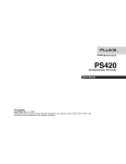
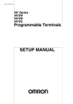
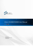
Chapter 5 GUI Installation and Operation In the Control Panel window, double click the "Add/Remove Program" icon. The following window will open. Find the GUIMGR icon as shown below. Figure 5.18 Add/Remove Programs window Click the "Change/Remove" button. Figure 5.18 Confirm application removal, click "Yes" to continue uninstall. Figure 5.20 Uninstall completed successfully, then click "OK". The GUIMGR computer program has now been completely uninstalled from your computer. The registry entries created by the GUIMGR installation are not deleted. The password used to operate the GUI software is stored in the registry at: HKEY_LOCAL_MACHINE/SOFTWARE/GUIMGR/config/Pass_word The default password is "1021". To remove all traces of the GUIMGR from the registry, delete GUIMGR under the HKEY_LOCAL_MACHINE/SOFTWARE location. 5-11 Chapter 5 GUI Installation and Operation 5.5. SNMP Card Configuration 5.51 Introduction The FRM301/401 SNMP card is an optional component, installed in the FRM301/401 chassis, and provides Telnet and SNMP access. The setting of the SNMP card is performed through the terminal console port of the FRM301/401. 5.52 HyperTerminal™ settings The settings for console port communication with the FRM301/401 are 38.4K baud, 8 bits, no parity, 1 stop bit and no flow control. In the HyperTerminal program terminal window click the "properties" icon and set the communication parameters as in the following graphics. Click the "Configure…" button in the properties window and set the port settings. When set properly, click "OK". Figure 5.21 HyperTerminal port settings for FRM301/401 5.53 Connecting to the FRM301/401 The console port of the FRM301/401 is an RS-232 interface (DCE) that utilizes a DB9F connector. Use the configuration cable that is supplied with the FRM301/401 or prepare a three wire DB9(F) to DB9(M) cable with the following pinout: DB9(M) 5 2 3 signal GND TD RD DB9(F) 5 2 3 5-12 Chapter 5 GUI Installation and Operation Figure 5.22 FRM301/401 main screen in console mode. Connect the PC running HyperTerminal to the FRM301/401 that has an installed SNMP card option. The above screen indicates successful communication with the FRM301/401. 5.54 FRM301/401 menu system Details of the menu system operation and meaning of menu items are described in detail in the FRM301/401 User's Manual. The following information is only for configuration of the SNMP option for use with a network management system. 5-13 Chapter 5 GUI Installation and Operation 5.55 SNMP Card settings From the main welcome screen, press "S" to enter the system configuration of the FRM301/401. ************************************************************** *** FRM-301 Fiber Optical Media Converter Rack Management *** *** V3.42 *** ************************************************************** System Configuration and TFTP Setup Menu: MAC Address : 0002AB025678 1:IP Address : 192.168.0.218 2:Subnet Mask : 255.255.255.0 3:Gateway IP : 192.168.0.254 4:TFTP Server IP : 192.168.0.45 5:TFTP Server Path : /300.bin Command Function Key: '1' to '5': Configure Setting 'R': Reset All Setting to Default 'S': Store Setting and Reboot 'T': TFTP and Flash 'ESC': Main Menu Figure 5.23 FRM301 main screen in console mode ************************************************************** *** FRM-401 Fiber Optical Media Converter Rack Management *** *** V3.22 P.6 *** ************************************************************** System Configuration and TFTP Setup Menu: MAC Address : 0002AB01FFFF 1:IP Address : 172.24.1.8 2:Subnet Mask : 255.255.0.0 3:Gateway IP : 172.24.190.254 4:TFTP Server IP : 172.24.1.126 5:TFTP Server Path : c:\f45v322.bin Command Function Key: '1' to '5': Configure Setting 'R': Reset All Setting to Default 'T': TFTP and Flash 'X': System Reset 'ESC': Main Menu (store and reboot if values are changed) Figure 5.24 FRM401 main screen in console mode 5-14 Chapter 5 GUI Installation and Operation 5.56 SNMP Agent Configuration The "agent" is the FRM301/401 SNMP. The IP address, subnet mask, default gateway, and TFTP server's IP address/path are all set within the System Configuration. Select "1" IP Address IP Address->172.24.1.3 Key-in the IP address for the SNMP agent in the FRM301/401. This IP address is also the Telnet IP address of the FRM301/401 rack. Select "2" Subnet Mask Subnet Mask->255.255.0.0 Key-in the subnet mask for the agent. Select "3" Gateway IP Gateway IP->172.24.190.254 Key-in the default gateway IP address. Select "4" TFTP Server IP TFTP Server IP->172.24.1.126 Key-in the IP address of a server running the TFTP protocol (trivial FTP) used for updating the SNMP firmware image in the SNMP card. Select "5" TFTP Server Path TFTP Server Path->d:\342.bin Review the settings and make any necessary corrections. If all entries are correct press "S" to Store Settings and Reboot the SNMP agent. 5-15 Chapter 5 GUI Installation and Operation 5.57 Manager Configuration From the SNMP main menu, select item "M", Manager Configuration Setup. Manager configuration is required to tell the agent (the SNMP card) who has authority to access the SNMP via "Get" commands (read) or "Set" commands (write) and where to send "trap" messages (unsolicited messages that are usually generated by alarms in the FRM301/401). ************************************************************** *** FRM-301 Fiber Optical Media Converter Rack Management *** *** V3.42 *** ************************************************************** Manager Configuration: Access Password: disable Community String #1 (Read/Write): public Community String #2 (Read Only) : * Access IP SNMP Community Trap =============== ============== ==== #1:* public Yes #2:* * * #3:* * * #4:* * * Command Function Key: '1': Edit Access IP#1 '3': Edit Access IP#3 '2': Edit Access IP#2 '4': Edit Access IP#4 '5': Edit Community#1 String (Read/Write) '6': Edit Community#2 String (Read Only) '7': User Password '8': Manager Password '9': Access Password ON/OFF 'R': Delete All Setting 'ESC': Main Menu 5-16 Chapter 5 GUI Installation and Operation The manager configuration has the ability to setup access for up to four (4) different management workstations. The community strings act like passwords in dealing with the device via SNMP protocol. By changing the community strings for read / write ('public' in this case) and read only (undefined here) access, and assigning a community string to an access IP, an administrator can control access to the FRM301/401. Enter the IP address of the management workstation that will be running the GUIMGR software, the access authority and whether or not it will be sent trap messages. Select "1": IP('*':disable) ->172.24.1.126 #IP of manager community '1' or '2'->1 #Manager has r/w privilege trap 'y'es or 'n'o->y #Manager will be sent trap messeges Here are the results of our management configuration. ************************************************************** *** FRM-301 Fiber Optical Media Converter Rack Management *** *** V3.42 *** ************************************************************** Manager Configuration: Access Password: disable Community String #1 (Read/Write): public Community String #2 (Read Only) : * Access IP SNMP Community Trap =============== ============== ==== #1:172.24.1.126 public Yes #2:* * * #3:* * * #4:* * * Command Function Key: '1': Edit Access IP#1 '3': Edit Access IP#3 '2': Edit Access IP#2 '4': Edit Access IP#4 '5': Edit Community#1 String (Read/Write) '6': Edit Community#2 String (Read Only) '7': User Password '8': Manager Password '9': Access Password ON/OFF 'R': Delete All Setting 'ESC': Main Menu When leaving the Manager Configuration menu, the changes are automatically saved. Note that in the above example, the management workstation with IP address 172.24.1.126 and using the community string 'public', has full read and write access and receives traps. If your management workstation has a different IP address, modify the above settings for your application. It is highly recommended that the read/write community string 'public' be changed using the menu selection '5'. Please also note that community strings are case sensitive. (public is not equal to Public) 5-17 Chapter 5 GUI Installation and Operation 5.6. GUIMGR Configuration and Operation 5.61 Introduction This chapter assumes that the GUIMGR application has already been installed on the workstation as in Chapter 1 and that the SNMP agent has been correctly configured as in Chapter 2. This chapter will detail the GUIMGR configuration and the operation of the software in monitoring and controlling the FRM301/401 multiplexer. 5.62 Configuration 5.62.1 Start the GUIMGR application Start the application by clicking the Windows "Start" button => Programs => SNMP GUIMGR => GUIMGR. A login password is required to enter the application. The password set from initial installation of the software is "1021". The user password may be changed via the "Config" pull down menu. Trial versions only need to click the "exe" file or shortcut and by default have no password set. Figure 5.25 GUI manager login Figure 5.26 GUIMGR first started 5-18 Chapter 5 GUI Installation and Operation The GUIMGR behaves just like any other Windows® application. The following graphic shows all of the areas that may be clicked for further configuration. Some items are 'greyed' out until the application has connected with an actual FRM301/401 unit. Trap Window Figure 5.27 Selectable features of the Main GUIMGR 5.62.2 Configure user password Click on "Config" from the window menu bar. Figure 5.28 Configuration Form Use this form to change the user password for the GUI. Note also that trap messages may be sent to a text file for logging, output to the default printer, and/or issue a warning beep on the PC. 5-19 Chapter 5 GUI Installation and Operation 5.62.3 Edit the SNMP Agent Click on "Edit" from the window menu bar to enter the Edit SNMP Agent Window. Figure 5.29 Edit the SNMP Agent The entries already entered are there by default if the software was just installed. They are just for reference as examples of how the format should be entered into the window. If we continue with our example from the previous chapters, then the FRM301/401 unit which we wish to manage (the agent) is at IP address 172.24.1.3 and the r/w community string is 'public'. So we will click in the lower window (or select the already entered text) and backspace over it until the window is empty. Then we will enter our own format string: 1 172.24.1.3 public FRM301 Then click the "Save" button. Now the GUIMGR is set to manage a FRM301/401 at IP address 172.24.1.3 with a community string of 'public' and our manager will display the rack name as FRM301. 5-20 Chapter 5 GUI Installation and Operation 5.63 Operation The interface for the GUIMGR program is a point and click Windows® application that requires little use of the keyboard. Trap Display Window Figure 5.30 Operational GUIMGR screen From the operational screen, the status of all rack units may be displayed. The Pwr and Fan indicators will display "green" when two power supplies are active and their fans are operating normally. Line card types are shown and link status displayed by color code: "Green" status indicates that both the fiber and copper are linked. "Yellow" indicates loss of link on the copper side. "Magenta" indicates loss of link on fiber side. "Grey" indicates neither copper nor fiber linked "Black" color indicates an empty line card slot or un-identified card. If all line cards are shown with "Red" color, it indicates a communication error. Possibly the configuration is not correct or there is a network error that prevents the manager from communicating with the agent. The trap window at the bottom displays trap messages, indicating the source IP address, the time stamping of the trap and the trap message itself. New messages are displayed from the top, down. The "Clear Trap" button will erase all of the traps displayed and stored in memory. 5-21 Chapter 5 GUI Installation and Operation 5.63.1 Rack Detail From this main display, we can view the details of any rack by clicking on the "Rack" button for that particular rack. Select the first device by clicking on the "Rack 1" button. A new window will open displaying the rack's front and rear panel details. Figure 5.31 Rack 1's GUIMGR screen Figure 5.32 FRM401 Rack GUIMGR screen The front panel graphic shows the operational state of all the installed line cards. The LED indications are shown in real time. Fan and power status are also displayed in "green". A "Red" indication on any of the fans, power supplies, or power supply fans indicates device or power failure. 5-22 Chapter 5 GUI Installation and Operation 5.63.2 Ethernet Line Card Settings Click the button marked "Chx". From this window we can display the individual line card's status, setup the card's working status, configure the UTP and fiber modes, get the remote unit's status or do loop back functions. Use the "Get" button to read the card's status. Use the "Set" button to write new status to the card. (The operations are all preformed via SNMP protocol.) Figure 5.33 Ethernet Line Card Settings (FRM301 & FRM401 shown) The card slot, type, address of machine and machine type are shown in the header information. The 'Command Set' window is used for channel enable/disable, UTP mode setting, Fiber mode setting, LLF function enable/disable, and normal or extended packet frame length setting. The settings may be set to default, loaded from a configuration file previously saved on the PC, or saved to PC. The 'Read' button will get all the settings for this card. The 'Modify' button will set the settings selected to the card. The 'Modify All' button will take the displayed settings and write them to every card of the same type in the rack. 5-23 Chapter 5 GUI Installation and Operation 5.63.3 Remote Functions The lower half of the window addresses the functions that can be performed when the fiber is connected to an FIB1-10/100 remote unit. Both of these functions are performed "in-band" and will cause a momentary loss of transmission in the link while they are being performed. The 'Remote Loop Back Test' button will test the fiber link by issuing a loopback code, sending pattern data, verifying the pattern data and then removing the loopback for normal transmissions. Figure 5.34 Loopback test with CPE The 'Get Remote CPE Status' button will attempt to identify and read all the settings in the remote CPE unit. Figure 5.35 Remote Status for CPE The card type, UTP and Fiber link status and other settings are all displayed for the remote side CPE. Click the "Close" button to close the Card Setting window. 5-24 Chapter 5 GUI Installation and Operation 5.63.4 Gigabit Ethernet Line Card Settings Click the button for a 1000Base line card to view and configure the local line card. Under the GUI, the card's status, Tx/Rx Duplex mode and LLF function may be read or modified. Figure 5.36 Gigabit Line Card Settings** The functions are very similar to those of the 10/100 Ethernet converter. When connected to an FIB1-1000, the loop back and get remote status functions may be used as well. **Not available for the FRM401. 5-25 Chapter 5 GUI Installation and Operation 5.63.5 E1/T1 Line Card Settings If an E1/T1 Line Card is installed in any slot, the status of the E1/T1 link, port settings and loop back functions may be viewed by clicking the channel button. Use the 'Get' button to read settings and the 'Set' button to send any modifications to the line card. Figure 5.37 E1/T1 Line Card Settings** **Not available for the FRM401. The command sets may be performed on the local converter in the rack or on the remote FIB1-E1/T1 fiber converter. The LEDs show the real time status of the card and remote converter. A full set of loop back functions are available. Figure 5.38 E1/T1 Loop Back Functions 5-26 Chapter 5 GUI Installation and Operation 5.7 Troubleshooting 5.71 Network Settings 5.71.1 Review Agent Settings During unit startup, the "SNMP" LED will light as the agent boots up, then it should blink at about one cycle per second after boot up and during normal operation. Refer to section 2.5.1 of the SNMP agent settings. Be sure you have a valid IP address for the attached network, that the subnet mask is properly set and that the default gateway is set if you wish to manage the FRM from a remote network. Attach a network cable to the FRM's front panel LAN/SNMP connector using a straight cable if connecting to a HUB or a cross over cable if connecting directly to another MDI device, such as direct connection to a workstation. The Link LED should be on or flashing. No link LED means no link. From any PC on the network, confirm the agent can be pinged. Figure 5.39 Ipconfig and Ping The "ipconfig" command from a command window in NT will display the workstation's IP, subnet and gateway settings. The "ping" command will send an ICMP protocol message to the agent, which in turn should reply. If no reply, double check all network connects, connect directly from a workstation to the FRM, or as a last resort replace the SNMP card of the FRM. 5-27 Chapter 5 GUI Installation and Operation 5.71.2 Review Manager Settings For the GUIMGR to connect to the FRM for management, the FRM's SNMP must be properly configured with the manager's IP address and authorized for read/write (via community string setting) and trap messages. Review the settings explained in 2.5.2. Review the "Edit" settings in 3.2.3 of the GUIMGR application, and confirm that the monitor mode is set to "1", IP address and community string for read/write match those as set from section 2.5.2. If the management workstation is on a remote network, ensure it can also pass the ping test. Figure 5.40 Ipconfig and Ping Remote Network Check with your network administrator to ensure that any firewalls in place will allow passing of SNMP protocol in order to connect with an FRM on a remote network. By default SNMP uses port 161. Always check all connections and double check all configurations. We have tested the FRM and GUIMGR extensively on local networks, on remote networks through bridges and routers and even over wireless links. You should not experience any problems if you follow each and every step in this guide. We hope you enjoy using the FRM with SNMP option and GUIMGR manager software. 5-28 Appendix A A.1 Alarm Messages You may see the description for the alarm message displayed at the alarm message area in the GUI main display menu. The "Bold" and "Italic" character is what you see on the monitor and normal character on the next line is the description for the alarm message. Slot xx Converter Card Inserted Æ Slot number xx was inserted with the converter card Slot Converter Card Removed Æ The converter card was removed from slot number xx Slot xx CH. xx Ethernet link up. Æ The Ethernet link is connected on the channel number xx of slot number xx Slot CH. Ethernet link down. Æ The Ethernet link is disconnected on the channel number xx of slot number xx Slot CH. Fiber link up. Æ The fiber link is connected on the channel number xx of slot number xx Slot CH. Fiber link down. Æ The fiber link is disconnected on the channel number xx of slot number xx Cool Fan NO. down. Æ The cooling fan number x (on the rear panel ) is defective Power Fan down. Æ The cooling fan number x (on the power card) is defective Power Card down. Æ The power card number x is defective Slot CH. Get Remote (CPE) Side data fail. Æ The result for the converter card on the slot number xx running the "get remote CPE status" has failed Slot CH. Get Remote (CPE) Side data success. Æ The result for the converter card on the slot number xx running the "get remote CPE status" has succeeded Slot CH. Loop Back test fail. Æ The result for the converter card on the slot number xx running the "loop-back test" has failed Slot CH. Loop Back test success. Æ The result for the converter card on the slot number xx running the "loop-back test" has succeeded User Login NMS Terminal . (usually the IP address comes in front of it) Æ The user of the specific IP address's rack logins in the NMS mode Illegal Login ! Æ The user of the specific IP address's rack logins in with the incorrect password Command err!! LBT or Get CPE is working ! Æ The user was trying to give another command while the system is already process the command of "loop-back test" or "get remote CPE status". The system won't take any more commands until the process is finished. A-1 Appendix A A.2 Trouble Shooting 1 No power ? Î Please examine an external 48-VDC outlet to a chassis ground connector, a negative (-) connector, and a positive (+) connector on the 48-VDC Power Supply Module 2 Already connected with the LAN cable but still no LAN connection ? Î Please check the push-button on the front panel, is it in the right position (MDI connection status). MDI-X (to PC) MDI (to HUB) 3 Already connected with fiber cable but the FX still no connection ? Î Please check the TX and RX sides for the right connections. 4 There is some loss generated during the transmitting the data ? Î Please check the optical fiber type is the right type for connection (single mode or multi-mode). And the fiber & power gain and the fiber connectivity. 5 After check the MDI status and the pin assignment of RJ-45 for MDI type, but still no connection ? Î Please check the configuration on the unit (n-way) or on the NMS. 6 The SNMP card has no connection. Î Please check the pin assignment of RJ-45 for MDI type with the following chart. RJ-45 Pin 1 2 3 6 MDI-X type Rx+ RxTx+ Tx- MDI type Tx+ TxRx+ Rx- 7 The "Terminal Mode" can't be connected. Î Please check the "Terminal Mode" setting procedure at section 4.4 on the manual. Carefully check the "Port Setting" 8 During the transmission, the LAN & Fiber Link LEDs are flashing. Does that means any wrong ? Î Please check the DIP switches on the PCB, the DIP switch#5 is the switch for setting the Link-Loss Forwarding, if the user enables the function, it will cause the LAN & Fiber Link LEDs are flashing. 9 The GUI SNMP Manager can't start. Î Please check the setting procedure for starting the GUI SNMP manger. See the "Client IP Setting" section start on the manual page 32. Choose the right procedure for your own platform version. 10 The duplex status & speed on the UTP port can't be modified Î Please check the DIP switch#2&3 on the PCB 11 The configuration for certain port can't be modified Î Please check the GUI SNMP Manager, on the chassis configuration menu, if the "Port Disable" is enabled, then it will freeze all the setting. A-2 Appendix B B.1 FRM401 Cards (Spec.) (all four converter interfaces per card are identical) 10BASE Media Converter Card Specifications Model 10M/ST2 10M/SC2 10S/ST14 Wavelength Fiber mode Connector Fiber cable Cable length 820nm Multi-mode ® ST type 62.5/125µm 2K meters 820nm Multi-mode SC type 62.5/125µm 2K meters 1310nm Single-mode ® ST type 9/125µm 14K meters 10BASE-FL models LED Indicator Details FX/RX FX/LINK UTP/RX UTP/LINK Flashing when Fiber Receive data activity On when Fiber Link OK Flashing when Ethernet Receive data activity On when Ethernet Link OK 100BASE& 10/100Base Media Converter Card Specifications Model 100M/ST2 100M/SC2 100M/MR2 100S/MR15 100S/ST30 Wavelength Fiber mode Connector Fiber cable Cable length 1310nm Multi-mode ® ST type 62.5/125µm 2K meters 1310nm Multi-mode SC type 62.5/125µm 2K meters 1310nm Multi-mode MT-RJ type 62.5/125µm 2K meters 1300nm Single-mode MT-RJ type 9/125µm 15K meters 1310nm Single-mode ® ST type 9/125µm 30K meters Model 100S/SC30 100S/MR40 100S/ST50 100S/SC50 100S/ST120 Wavelength Fiber mode Connector Fiber cable Cable length 1310nm Single-mode SC type 9/125µm 30K meters 1300nm Single-mode MT-RJ type 9/125µm 40K meters 1310nm Single-mode ® ST type 9/125µm 50K meters 1310nm Single-mode SC type 9/125µm 50K meters 1550nm Single-mode ® ST type 9/125µm 120K meters Model 100S/SC120 100W/SC20A 100W/SC20B 100W/SC40A 100W/SC40B Wavelength 1550nm Fiber mode Connector Fiber cable Cable length Single-mode SC type 9/125µm 120K meters Tx-:1310nm Rx:1550nm Single mode SC type 9/125µm 20K meters Tx:1310nm Rx:1550nm Single mode SC type 9/125µm 40K meters Tx:1550nm Rx:1310nm Single mode SC type 9/125µm 20K meters 100BASE-FX models LED Indicator Details FX UTP FULL On when Fiber link, flashing when data received On when Ethernet link, flashing when data received ON=Full Duplex, OFF= Half Duplex 100BASE-FX models Three Position Slide Switch Details FULL AUTO HALF Full Duplex Ethernet Mode Auto negotiation Half/Full Duplex Half Duplex Ethernet Mode 10/100BASE-FX models LED Indicator Details FX Link UTP Link FULL 100 On when Fiber link, flashing when data received On when Ethernet link, flashing when data received ON=Full Duplex, OFF= Half Duplex ON=100Base-TX, OFF=10Base-T 10/100BASE-FX models Two Position Slide Switch Details FULL HALF Full Duplex Fiber Mode Half Duplex Fiber Mode Environment Temperature Humidity 0 - 40C 10-90% non condensing Alarm relay contact ratings 125VAC 110VDC 30VDC 600mA 600mA 2A B-1 Tx:1550nm Rx:1310nm Single mode SC type 9/125µm 40K meters Appendix B B.2 FRM401-10 Card Receive data on fiber Ethernet Link status Fiber Link status Receive data on UTP Fiber Connection ST or SC Type FRM401-10 Card, 10Base-T to 10Base-FL Converters x 4 B-2 Appendix B B.3 FRM401-100 Card Full / Half Duplex Fiber Link/Data Reception UTP Link/Data Reception Fiber Connection ST, SC or MT-RJ Type Duplex Mode switch FRM401-100 Card, 100Base-TX to 100Base-FX Converters x 4 B-3 Appendix B B.4 FRM401-10/100 Card UTP Link/Data Reception UTP Duplex UTP Speed Fiber Link Fiber Connection ST, SC or MT-RJ Type The following DIP settings are followed if no SNMP card is in the system. 1 2 3 4 5 6 ON man half 10 LBT LLF 1536 OFF auto full 100 off off norm Default is all OFF. Fiber Duplex Mode switch FRM401-10/100 Card, 10/100Base-TX(auto) to 100Base-FX Converters x 4 B-4 Appendix B B.5 FRM401-10/100W (WDM) Card UTP Link/Data Reception UTP Duplex UTP Speed Fiber Link Fiber Connection SC Type WDM The following DIP settings are followed if no SNMP card is in the system. 1 2 3 4 5 6 ON man half 10 LBT LLF 1536 OFF auto full 100 off off norm Default is all OFF. Fiber Duplex Mode switch FRM401-10/100W Card, 10/100Base-TX(auto) to 100Base-FX Converters x 4 B-5 Appendix B B.6 Version Compatibility All compatibility issues for the FRM401 are dependant upon the SNMP hardware version used in the rack. There are two(2) hardware versions in service. The older SNMP, dubbed version 1, is based on the Intel I80188 CPU. The newer SNMP, dubbed version 2, is based upon the Samsung ARM7 CPU. The following is a physical representation of the two different SNMP versions. Version 1 SNMP does not support Telnet or TFTP upgrade functions. The terminal mode operation screens are different than those depicted in this manual. Please refer to the old version manual for this model. The final firmware versions for this model are: SNMP f/w ver.2.11 10Base-T Line card CPU f/w ver.1.00 100Base-TX Line card CPU f/w ver.1.00 GUI Manager s/w ver. 1.10 Version 2 SNMP, versions available as of this printing: (old model line cards may be upgradeable) SNMP f/w ver.3.22 10Base-T Line card CPU f/w ver.2.00 100Base-TX Line card CPU f/w ver.2.01 10/100Base Line card CPU f/w ver.2.10 10/100W (WDM) Line card CPU f/w ver. 2.10 GUI Manager s/w ver. 2.10 B-6 Appendix C C.1 FRM401 SNMP Upgrade Procedure The purpose of section is to outline the procedures and pitfalls in upgrading the SNMP of the FRM401. C.11 Preconditions The FRM401 must be using hardware version 2.0 SNMP card. Line cards in the rack must be using version 2.x CPU firmware version. If an SNMP option is being installed for the first time, now would be the time to upgrade the line card firmware. The line card CPU firmware upgrade is support by chip replacement only. The original version 2.0 hardware SNMP was released with SNMP code version 3.20 for the FRM401. The SNMP is upgraded by TFTP. The SNMP agent provides the ability to upload the new code, re-flash the flash memory and reboot with the new SNMP operational code. C.12 Items Required a. The FRM401 unit with SNMP option installed and network connection. Version 3.2X to be upgraded to version 3.22. b. A Windows® based PC with a network connection and with at least one free Com port, telnet and terminal emulation software (such as HyperTerminal). c. Serial console cable (DB9M to DB9F) d. Ethernet UTP cables e. SNMP ver. 3.22 binary image file f. CTC Union TFTP server for Windows® (or other TFTP server) C.2 Equipment Setup The upgrade procedure could possibly have effect on the traffic passing through an online FRM401 unit. It is recommended that the unit be taken offline for maintenance. Obviously, changing of Line Card firmware requires removing the cards. The procedure for removing Line cards or power modules is all outlined in the User's Manual and will not be repeated here. Two connections are required between the PC that will do the upgrade and the FRM401 that will be upgraded. First, a console connection, with terminal emulation program such as HyperTerminal with settings of 38.4K baud, 8 bits, no parity, 1 stop bit, and no flow control. The second connection is an Ethernet connection, either through a network or with a direct connection and crossover UTP cable. Check the Ethernet settings of the FRM401 through the console mode. Either change the settings to match the network settings of your PC or set the PC's settings to match the FRM401's network settings. In the following example, we are on a 172.24.0.0 network with a subnet mask of 255.255.0.0 and a default gateway of 172.24.190.254. Our PC is set with an IP address of 172.24.1.125 and our FRM401 has an IP address of 172.24.1.8. C-1 Appendix C C.21 Setup the FRM401 The following screens will show the detailed procedures to setup the networking for the FRM401 and prepare for TFTP upgrade of the SNMP. Once the console port is connected to a terminal, the following screen will display. ************************************************************** *** FRM-401 Fiber Optical Media Converter Rack Management *** *** V3.21 P.1 *** ************************************************************** password: Enter your password. If you forgot it, the super user password for terminal mode is '1021' (no quotes). ************************************************************** *** FRM-401 Fiber Optical Media Converter Rack Management *** *** V3.21 P.1 *** ************************************************************** Main Menu and Rack Status: 1:Slot #1 >> 10/100 Base << || 7:Slot #7 >> 10/100 Base << 2:Slot #2 >> 10/100 Base << || 8:Slot #8 >> 10/100 Base << 3:Slot #3 >> 10/100 Base << || 9:Slot #9 >> Empty << 4:Slot #4 >> 10/100 Base << || A:Slot #10 >> Empty << 5:Slot #5 >> 10/100 Base << || B:Slot #11 >> Empty << 6:Slot #6 >> 10/100 Base << || C:Slot #12 >> Empty << Command Function Key: '1' to '9', 'A' to 'C': I/O Cards Setting 'P': Show Fans and Powers Status 'R': Refresh Status 'Q': Command Mode 'ESC' Logout 'S': System Configuration and TFTP Setup 'M': Manager Configuration Setup Console:[On line] Telnet:[Off line] GUI:[Off line] The actions we must first take are to configure the TCP/IP settings of the FRM401, if they are not already set. Next, we will setup the information required to access the TFTP server. Lastly, once the TFTP server is running on our network, we will execute the TFTP upgrade. C-2 Appendix C Select item 'S', "System Configuration and TFTP Setup" ************************************************************** *** FRM-401 Fiber Optical Media Converter Rack Management *** *** V3.21 P.6 *** ************************************************************** System Configuration and TFTP Setup Menu: MAC Address : 0002AB01FFFF 1:IP Address : 172.24.1.8 2:Subnet Mask : 255.255.0.0 3:Gateway IP : 172.24.190.254 4:TFTP Server IP : 0.0.0.0 5:TFTP Server Path : Command Function Key: '1' to '5': Configure Setting 'R': Reset All Setting to Default 'T': TFTP and Flash 'X': System Reset 'ESC': Main Menu (store and reboot if values are changed) If the TCP/IP settings are not already correct, use menu items 1-3 to set the FRM401 for your network. For menu items 4 and 5, set the IP address for the TFTP server or the PC running the TFTP Server deamon. Enter the path and filename where the image file is placed on the TFTP server. Now press 'ESC' to store the results and reboot the SNMP agent. When the agent comes back up on our terminal, enter the password, if required, and again go to the "System Configuration and TFTP Setup" menu. ************************************************************** *** FRM-401 Fiber Optical Media Converter Rack Management *** *** V3.21 P.6 *** ************************************************************** System Configuration and TFTP Setup Menu: MAC Address : 0002AB01FFFF 1:IP Address : 172.24.1.8 2:Subnet Mask : 255.255.0.0 3:Gateway IP : 172.24.190.254 4:TFTP Server IP : 172.24.1.125 5:TFTP Server Path : e:\f45v322.bin Command Function Key: '1' to '5': Configure Setting 'R': Reset All Setting to Default 'T': TFTP and Flash 'X': System Reset 'ESC': Main Menu (store and reboot if values are changed) C-3 Appendix C Now we have the SNMP agent configured for the network and ready to be upgraded. Next we need to set the TFTP server. As you saw from the previous configuration, we have placed the upgrade binary file on our "E" drive, in the root directory. The file is called f45v322.bin. All that is needed now is to run the TFTP daemon program for Windows. It's a simple little proggy!! No configuration is required, just run it. Now your PC is a TFTP server! Here is what the TFTP server looks like when it is running. Now that we have our TFTP server set and the FRM401 ready, open up a command window on the PC and ping the FRM401, just to make sure the network connection is good. Go back through the terminal program and press 'T', to TFTP and flash the unit. Press it and at the prompt answer 'y' and press Enter. If you go to the TFTP server screen, you should see the server serving up the binary file to the IP address of the FRM401 and finish with an 'OK' Status. C-4 Appendix C The console (terminal mode), will display the following as the image file is uploaded, unit is flashed and then rebooted. ************************************************************** *** FRM-401 Fiber Optical Media Converter Rack Management *** *** V3.21 P.6 *** ************************************************************** System Configuration and TFTP Setup Menu: MAC Address : 0002AB01FFFF 1:IP Address : 172.24.1.8 2:Subnet Mask : 255.255.0.0 3:Gateway IP : 172.24.190.254 4:TFTP Server IP : 172.24.1.125 5:TFTP Server Path : e:\f45v322.bin Command Function Key: '1' to '5': Configure Setting 'R': Reset All Setting to Default 'T': TFTP and Flash 'X': System Reset 'ESC': Main Menu (store and reboot if values are changed) Are you sure? <y/n> y TFTP NOW, LOADING.... Loading ok! Please don't power off! Flashing now... oooooooooooooooooooooooooooooooo Flash completed! System reset! Please wait... Attached TCP/IP interface to secEnd unit 0 Attaching interface lo0...done Watch the 'Activity' LED of the SNMP on the front panel of the FRM401. When the LED returns to a constant 1 blink per second, the SNMP agent has rebooted. You may now 'Close' the TFTP server. OK, now let's verify the version number of the SNMP. To do that, just login to the terminal of the FRM401. ************************************************************** *** FRM-401 Fiber Optical Media Converter Rack Management *** *** V3.22 P.1 *** ************************************************************** Main Menu and Rack Status: 1:Slot #1 >> 10/100 Base << || 7:Slot #7 >> 10/100 Base << 2:Slot #2 >> 10/100 Base << || 8:Slot #8 >> 10/100 Base << 3:Slot #3 >> 10/100 Base << || 9:Slot #9 >> Empty << 4:Slot #4 >> 10/100 Base << || A:Slot #10 >> Empty << 5:Slot #5 >> 10/100 Base << || B:Slot #11 >> Empty << 6:Slot #6 >> 10/100 Base << || C:Slot #12 >> Empty << Command Function Key: This completes the SNMP upgrade procedure. C-5 Appendix C This page left blank intentionally. C-6 Fiber Series Units CTC Union Technologies Co., Ltd. Far Eastern Vienna Technologies Center (Neihu Technology Park) 8F, No. 60, Zhouzi St., Neihu, Taipei, Taiwan Phone:(886) 2.2659.1021 Fax:(886) 2.2.799.1355 E-mail: [email protected] http://www.ctcu.com