1
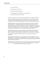
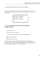
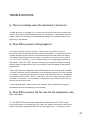
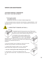
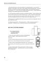
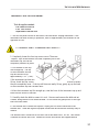
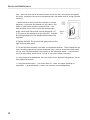
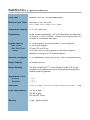
USER’S MANUAL
Air Vent
Caution Hot
Capillary
Tube
Modules
Keypad
Display
Screen
SAFETY AND REGULATORY INFORMATION
This symbol warns the user to operate the machine according to the
instructions provided in this manual. If used otherwise a potentially
hazardous situation could result.
This symbol highlights tips on how to operate this instrument more
efficiently.
This label is placed next to the fuse and power switch and alerts the user to
wait three seconds before restarting the instrument. It also contains the fuse
requirements for this machine.
Note: Always maintain this instrument in good working order. If the
instrument experiences an extreme environmental event, return it to Idaho
Technology for a complete service inspection. See Appendix A for return
instructions. If Rapid Cycler 2 is used in a manner other than described in
this manual, it may impair equipment protection and performance.
© Copyright 2004, Idaho Technology Inc.
Rapid Cycler® 2 Instrument User’s Manual - RCL2-PRT-0004, Rev 01
All rights reserved. Printed in the United States of America
Rapid Cycler is a registered trademark of Idaho Technology Inc. Patent pending
The information contained in this document is subject to change without notice.
Idaho Technology makes no warranty of any kind with regard to this material, including, but not limited to the
implied warranties of merchantability and fitness for a particular purpose. Idaho Technology shall not be liable for
errors contained herein or for incidental consequential damages in connection with the furnishing, performance
or use of this material.
PCR is a proprietary technology covered by several US patents including US Patent Nos. 4,683,195, 4,683,202 and 4,965,188, and by
issued and pending counterparts outside the U.S. These patents are owned by Roche Molecular Systems Inc (RMS) and have been sublicensed by PE Corporation (PE) in certain fields. Depending on your specific application you may need a license from RMS or PE to
practice PCR. Additional information on purchasing licenses
to practice the PCR process may be obtained by contacting the Director of Licensing at Roche Molecular Systems, 1145 Atlantic
Avenue, Alameda, CA 94501 or Applied Biosystems (a.k.a. PE), 850 Lincoln Centre Drive, Foster City,
CA 94404.
1
CUSTOMER AND TECHNICAL SUPPORT
Reach Us On the Web
Idaho Technology’s Web site is http://www.idahotech.com
We strongly encourage users to visit our Web site for answers to frequently
asked questions, additional Rapid Cycler 2 manuals, parts and accessories.
Reach Us By E-mail
Contact Idaho Technology by e-mail in the following areas:
[email protected] - Customer Support
[email protected] - General Support
Reach Us By Phone
Technical support is available during the following times:
8 a.m. to 5 p.m. - Mountain Standard Time
For technical support call:
1-800-735-6544 - United States and Canada
1-801-736-6354 - Utah
IDD Prefix-1-801-736-6354 - International
Reach Us By Fax
To contact Idaho Technology by fax, use the following numbers:
1-801-588-0507 - United States and Canada
IDD Prefix-1-801-588-0507 - International
2
CONTENTS
Safety and Regulatory Information .......................................................... 1
Customer and Technical Support ............................................................ 2
INTRODUCTION ................................................................................. 5
SETTING UP YOUR RAPID CYCLER 2 INSTRUMENT ......................................... 7
PROTECTING YOUR RAPID CYCLER 2 INSTRUMENT ........................................ 7
RAPID CYCLING WITH GLASS CAPILLARY TUBES ........................................... 8
1. SAMPLE PREPARATION................................................................. 8
2. LOADING SAMPLES INTO CAPILLARY TUBES ....................................... 8
3. CYCLING ............................................................................... 9
4. AFTER CYCLING ....................................................................... 9
PROGRAM MODES AND USER INTERFACE .................................................... 11
1. RAPID CYCLER FUNCTION: ........................................................... 11
2. USER INTERFACE: EDITING NUMBERS ............................................. 11
CYCLE MODE .................................................................................... 12
1. DESCRIPTION OF CYCLE MODE PARAMETERS....................................... 12
2. CHANGING BETWEEN AND EDITING PROGRAMS ................................... 13
3. A CYCLE PROGRAM MUST MEET THE FOLLOWING CRITERIA TO RUN .......... 13
4. RUNNING A CYCLE PROGRAM ........................................................ 14
HOLD MODE ..................................................................................... 15
1. CHANGING BETWEEN AND EDITING PROGRAMS ................................... 15
2. RUNNING A HOLD PROGRAM ........................................................ 16
3
LINK MODE ...................................................................................... 17
1. CHANGING BETWEEN AND EDITING PROGRAMS ................................... 17
2. RUNNING A LINK PROGRAM........................................................... 18
RAPID CYCLER’S MEMORY ..................................................................... 19
1. FACTORY-SET PROGRAMS ............................................................ 19
2. PROGRAM TABLES ..................................................................... 19
TROUBLE-SHOOTING ........................................................................... 25
Q. There is no display when the instrument is turned on? ......................... 25
Q. When RUN is pressed nothing happens? ........................................... 25
Q. When RUN is pressed, the fan runs but the
temperature does not increase? ................................................... 25
Q. There is unusual noise coming from the machine? .............................. 26
Q. The machine is slow to cool down
(>15 sec. from denaturation to annealing temperatures)? .................... 27
SERVICE AND MAINTENANCE .................................................................. 29
LIGHT BULB REPLACEMENT.............................................................. 29
ELECTRIC FUSE REPLACEMENT .......................................................... 30
THERMAL FUSE REPLACEMENT .......................................................... 31
PERIODIC MAINTENANCE LIST ........................................................... 33
Appendix A: Return and Decontamination Forms ......................................... 37
The following forms have been provided: ............................................ 37
Returned Equipment Procedure ........................................................ 38
Warranty & Upgrades .......................................................................... 43
Warranty ................................................................................... 43
Upgrades ................................................................................... 43
4
INTRODUCTION
The Rapid Cycler® 2 is a rapid
temperature cycling system
based on heat transfer by hot
air to samples contained in
Roche LightCycler® capillary
tubes. The Rapid Cycler was
specifically designed to quickly
amplify samples that can then
be analyzed on Idaho Technology’s HR-1™
instrument without opening the sample
vessel. Standard gel electrophoresis
methods can also be used to analyze
amplified products.
Temperature transition rates in most
thermal cyclers average approximately
1° C/sec when metal blocks or water are used for thermal equilibration and samples
are contained in plastic microfuge tubes. A significant portion of the cycle time is
spent heating and cooling the sample, as opposed to being spent at specific target
temperatures. Long reaction times of 2-6 hours are common, and slow transition
rates make it difficult to determine optimal temperatures and times for each stage of
the cyclic reactions. Instantaneous temperature changes are not possible because of
sample, container and cycler heat capacities. “Second generation” instrumentation can
complete 30-cycles in about one hour. It is unlikely any instrument based on samples
contained in conical tubes with heating and cooling through a metal block can achieve
faster cycles at any price. However, with capillary tubes and air heating, transition
rates of 5-10°C/sec are easily obtained. Complete 30-cycle reactions can be finished in
as little as 20 min.
The advantages of an air-cycling system include simplicity and rapid temperature
cycling. Air is an ideal heat transfer medium that can change temperature quickly
because of its low density. Temperature homogeneity problems are solved by rapidly
mixing air with a fan to provide homogeneous temperature exposure over the sample
containers. The sample container is just as important as the heat transfer medium. An
optimal sample container should be water-vapor tight and have:
5
Introduction
(i) Low thermal mass
(ii) Good thermal conductivity
(iii) Minimal internal condensation
(iv) Easy sample recovery without cross contamination
(v) No adverse effects on the reaction
Whatever the container material, temperature equilibration will always be achieved
faster if the sample volume is small, if the container wall is thin, and if the surfaceto-volume ratio of the sample exposed to the container wall is high. Problems with
condensation can be reduced by minimizing the free air space surrounding the sample.
Microfuge tubes are kept water-vapor tight by mechanical closure and, if necessary,
overlaid mineral oil. Thermal conductivity is poor because of the material and its
thickness (about 1 mm). Internal condensation can occur if mineral oil is not used and
particularly if different parts of the tube are at different temperatures. Sample mixing
by convection has been used in conical tube instruments. The temperature gradients
that cause convection are not ideal for a temperature-dependent reaction.
Glass capillaries conduct heat to the sample more efficiently than microfuge tubes
because of decreased wall thickness and a better surface-to-volume ratio. Dead air
space is minimized to prevent significant condensation. Different volumes of a sample
can be placed in the same diameter capillary tube so that rapid heat transfer is
maintained.
Decreasing the heat capacity of the cycling system can markedly decrease the total
time required for reactions that require temperature cycling. In addition, air cycling and
miniaturization can significantly decrease the costs of reagents and the personnel time
required to optimize reactions.
The high surface area to volume ratio of the capillary tubes and the use of the air as the
cycling medium can approach the kinetic limits of amplification reactions, making the
Rapid Cycler 2 one of the fastest thermal cyclers in the world.
6
SETTING UP YOUR RAPID CYCLER 2 INSTRUMENT
In choosing a location to set up your Rapid Cycler 2, remember that it uses room air
for cooling. Keep the Rapid Cycler 2 open on all four sides to allow air to flow into the
air intake beneath the machine. Also, do not set the Rapid Cycler 2 on any material
which may be sucked into or cover the intake.
NOTE: Placing the Rapid Cycler 2 on a lab bench covered with
absorbent paper should be avoided.
Heated air (up to 90°C) is expelled from the top rear of the Rapid Cycler
2, so it is important that the exhaust area be kept clear to avoid restricting
the airflow through the instrument. Be especially careful to keep the
exhaust area clear of anything that could be damaged by heat, particularly
volatile organic solvents.
PROTECTING YOUR RAPID CYCLER 2 INSTRUMENT
Plug the power cord into the Rapid Cycler 2 and into a grounded surge suppressor. The
Rapid Cycler 2, like all microprocessor controlled equipment, is sensitive to damaging
power fluctuations.
7
RAPID CYCLING WITH GLASS CAPILLARY TUBES
Using a capillary based air cycler is different from using a heat block instrument.
Following are instructions for sample preparation, loading samples into capillary tubes,
cycling and sample analysis.
1. SAMPLE PREPARATION
PCR reactions in glass capillary tubes should contain 250-500 mg/ml bovine serum
albumin to prevent surface denaturation of the enzyme. The same high surface-areato-volume ratio that allows rapid temperature cycling also provides many sites for
enzyme inactivation. We recommend three alternatives for adding adequate BSA to your
reaction:
1. Add 10X BSA (2.5 mg/ml) to your master mix. You can either make the solution
yourself, or purchase directly from Idaho Technology (10X 2.5 mg/ml BSA part
no. 1777, component of LCGreen™ I kit) .
2. Dilute your concentrated enzyme stock to a 10X enzyme solution with an
enzyme diluent containing BSA (10 mM Tris, pH 8.0, 2.5 mg/ml BSA). You can
make the diluent yourself or purchase directly from Idaho Technology (Enzyme
Diluent part number 1773, component of LCGreen I kit).
3. Acquire from Idaho Technology 10X buffers that already contain BSA. These
buffers are optimized for rapid cycling and include 10mM, 20mM, 30mM, 40mM
or 50mM MgCl2 buffers. (10, 20, and 30 mM MgCl2 buffers included in LCGreen
I kit)
2. LOADING SAMPLES INTO CAPILLARY TUBES
After the samples have been prepared, they
can be loaded directly into capillary tubes by
using a pipettor. After the tubes are capped,
insert them into the holes in the capillary
modules located in the instrument top. This
will place the sample column completely into
the air chamber. Program and operate the
cycler as detailed in section 4, Programming.
���������
��������
�����������
�����������
���������
�����������
���
����������
�������
���
�����������
�����������
8
RapidCycling with Glass Capillary Tubes
3. CYCLING
For information on how to enter and run a program see Section 4, Programming. The
choice of cycling protocols depends on many factors such as reaction volume and length
of product. Keep in mind that the Rapid Cycler 2 is optimized to run 10 µl reactions.
Larger reaction volumes will likely require longer hold times at each temperature to
allow for sample equilibrium.
4. AFTER CYCLING
After cycling is complete, remove capillaries from the modules and
place them on a rack for transfer. If samples are to be analyzed on the
HR-1 there is no need to open the sample vessel. Always wear gloves
when handling glass capillaries! Oils from hands can interfere with the
fluorescence properties of the HR-1 instrument.
To analyze samples using standard gel electrophoresis methods, remove
capillaries from the modules and place them on a rack for transfer. Once
ready to run samples on a gel, carefully remove the caps and invert
capillaries in 1.5 ml centrifuge tubes. Change gloves frequently as a
precaution for spreading amplicon. Perform a quick spin of centrifuge
tubes (for about 5 seconds) to draw out the samples from the capillaries.
Check to make sure that the entire sample is found at the bottom of the
centrifuge tube. Add a gel loading dye. Load samples into a gel.
Note: Store samples at 4ºC if they cannot be run on a gel
on the same day they were amplified.
9
RapidCycling with Glass Capillary Tubes
10
PROGRAM MODES AND USER INTERFACE
1. RAPID CYCLER FUNCTION:
When you switch the Rapid Cycler 2 on, a title
screen which contains the software version
number is displayed while the controller boots
up. After a few seconds, the RAPIDCYCLER
FUNCTION screen appears. This is the main
menu of the Rapid Cycler 2 To enter one of the
three operating modes of the Rapid Cycler 2
simply press the corresponding number:
RAPIDCYCLER FUNCTION:
1. CYCLE MODE
2. HOLD MODE
3. LINK MODE
To return to the RAPIDCYCLER 2 FUNCTION
screen from within the three modes, press the FUNCTION key. If you have pressed
RUN/STOP in any of the modes while you are running a program, you must first stop the
program by pressing RUN/STOP, then press FUNCTION to return to the RAPIDCYCLER 2
FUNCTION screen.
At start-up, program number 01 in each of the three modes is reset to the default
parameters found in the Program Tables at the end of this section. The other 98
programs in each mode retain whatever values have been entered by the user.
If you have not already done so, you may wish to familiarize yourself with the function
of the machine by entering each of the three modes and pressing RUN/STOP. Cycle
program C-01 will take about 15 minutes but can be stopped at any time by pressing
RUN/STOP. Hold program H-01 only takes a few minutes. Link program 01 runs hold
program H-01 and cycle program C-01 in sequence and can also be interrupted at any
time by pressing RUN/STOP.
2. USER INTERFACE: EDITING NUMBERS
Programming the Rapid Cycler 2 is easy. It is done by first entering Cycle, Hold, or Link
mode. Move the blinking cursor using the cursor keys (arrows), and enter the desired
values using the numeric keypad.
When editing a number, remember to type in the same number of digits as the number
you are editing. For example, if you want to change the program number from “01”
to “02”, type “0” and “2” - rather than just typing “2”. Programs 02 through 99 in
each mode will be retained by the Rapid Cycler even if the machine is turned off or
unplugged.
11
Program Modes and User Interface
CYCLE MODE
When you enter CYCLE MODE the screen should appear as follows:
CYCLE MODE
PROG#C01
TEMP
D94 A55 E72
TIME 0:00 0:00 00:15
SLOPE=9.9 CYCLES=30
1. DESCRIPTION OF CYCLE MODE PARAMETERS
PROG# C01: Program number C (01 THROUGH 99)
TEMP: Temperatures in °C (~30°C - 99°C)
D: Typically 90° - 96°
A: Typ. 40° - 68°
E: Typ. 70° - 74°
“D” - Denaturation, “A” - Annealing, “E” - Extension
TIME: Corresponding hold times in minutes and seconds
D: 0 sec for 10µl sample in capillary tube
A: 0 sec for 10µl sample in capillary tube and highest stringency
E: 1 sec/25 bp for products up to 2 kbp
1 sec/15 bp for products between 2-5 kbp
SLOPE: Ramp rate between A and E in °C/sec.
Typically 9.9 for highest stringency. Ramp rate between D to A,
and E to D is maxima, approximately 5º - 10º C/sec.
CYCLES: Number of cycles
12
Program Modes and User Interface
2. CHANGING BETWEEN AND EDITING PROGRAMS
Change to program #C03 by pressing 0 and 3. The parameters should all be null. Use
the cursor keys and numeric keys to enter the following temperatures, hold times, slope
and cycle count.
CYCLE MODE PROG#C03
TEMP D94 A65 E72
TIME 0:00 0:00 00:15
SLOPE=9.9
CYCLES=3
3. A CYCLE PROGRAM MUST MEET THE FOLLOWING
CRITERIA TO RUN
D must be greater than E
E must be greater than or equal to A
For two temperature cycling, set A=E with a 0 second hold at A
Slope must be greater than 0
Cycles must be greater than 0
Since there are many programs available it may be difficult to remember which
programs “belong” to whom. We suggest making copies of the Program Tables at the
end of this chapter and posting them near the Rapid Cycler 2. Name the Cycle, Hold,
and Link programs and thereby “claim” them as your own.
13
Program Modes and User Interface
������������������� �
����������
������������������������������������������
����������������������������������������
��������������������������������������
���������������� �
To edit a program, tab to the PROG# position and enter both digits of the program you
wish to modify. The program you were in will be saved automatically as you exit to the
new program number. Keep in mind that whenever you enter numbers, the program is
changed. If you edit a program that someone else routinely uses in a link program they
may not see the changes you have made and it may ruin their run.
4. RUNNING A CYCLE PROGRAM
After all required parameters are entered, you are ready to run the program. Press
“RUN/STOP” key to start the program. Should you want to stop the program before it
reaches completion, press the “RUN/STOP” to halt the program. The Rapid Cycler 2
will then return to the CYCLE MODE screen.
If you try to run a program that does not meet the criteria for a valid cycle program, the
Rapid Cycler 2 will display an error message and beep, then return to the program you
tried to run. See the “Changing between and editing programs:” section earlier in this
chapter for a list of the cycling criteria.
When running a cycle program the Rapid Cycler 2 displays the current temperature as
well as the cycle count. Line 3 of the display: “CYCLE 1 D OF 30” describes the cycling
status as being on the denaturation step of cycle #1 of 30 cycles.
After completion of a program, the Rapid Cycler 2 will display “PROGRAM
COMPLETED” and prompt you to “PRESS ANY KEY” to continue. While waiting for you
to press a key, the Rapid Cycler 2 will beep every thirty seconds to remind you that it
is finished. Once a key is pressed, the Rapid Cycler 2 will return to the CYCLE MODE
screen for the program you have just completed.
14
Program Modes and User Interface
HOLD MODE
When you enter HOLD MODE the screen should appear as follows:
HOLD MODE
PROG#H01
TEMPERATURE=94
TIME=00HR 00MN 15SEC
Description of HOLD MODE parameters:
PROG# H: Program number H(01 THROUGH 99)
TEMPERATURE: Temperature in °C (~30°C - 99°C)
TIME: Hold time in hours, minutes, and seconds
1. CHANGING BETWEEN AND EDITING PROGRAMS
Change to program #H03 by pressing 0 and 3. The parameters should all be null. Use
the cursor keys and numeric keys to enter a temperature of 94° and hold time of 15
seconds. The screen should appear as follows:
HOLD MODE
PROG#H03
TEMPERATURE=94
TIME=00HR 00MN 15SEC
Now create another hold program for an extended elongation period after cycling.
Select program 04 and enter 72° for 15 seconds.
The only requirement for a hold program to run is that the temperature can not be 0
or greater than 99, however, if a temperature below room temperature is entered the
machine will be unable to reach it.
15
Program Modes and User Interface
HOLD MODE
PROG#H04
TEMPERATURE=72
TIME=00HR 00MN 15SEC
2. RUNNING A HOLD PROGRAM
Press the “RUN/STOP” key to start the program. If you wish you may also press the
“RUN/STOP” to halt the program.
While running a HOLD MODE program the Rapid Cycler 2 displays the current
temperature and begins a count-down once the desired temperature has been reached.
After completion of a program, the Rapid Cycler 2 will display “PROGRAM
COMPLETED” and prompt you to “PRESS ANY KEY” to continue. While waiting for you
to press a key, the Rapid Cycler 2 will beep every thirty seconds to remind you that it
is finished. Once a key is pressed, the
Rapid Cycler 2 will return to the HOLD MODE screen for the program you have just
completed.
16
Program Modes and User Interface
LINK MODE
When you enter LINK MODE the screen should appear as follows:
LINK MODE
PROG#01
H01-C01-XXX-XXX-XXXXXX-XXX-XXX-XXX-XXX
Description of LINK MODE parameters:
PROG#: Program number (01 through 99)
10 LINK SEGMENTS
Up to 10 cycle or hold programs to be run sequentially. Cycle programs are designated
CXX and hold programs are HXX.
1. CHANGING BETWEEN AND EDITING PROGRAMS
Link mode can be programmed to run up to ten cycle or hold programs sequentially, but
the programs to be linked must fulfill all the criteria for cycle or hold programs for the
link program to run to completion. Segments are run in order from the upper left to
lower right. Empty segments are skipped.
Change to program #03 by pressing 0 and 3. The parameters should all be null, or 0.
Press the right arrow cursor key to enter the first link segment. To link hold or cycle
programs using a link program, you must enter 3 digits for each segment. The first digit
must be either a “1” or “2”, which represent a “C” for Cycle program or “H” for Hold
program respectively. Note that the “1” key has the word “CYCLE” on it and the “2”
key has the word “HOLD” on it. The next two digits represent the program number of
that cycle or hold program.
For example, if you want to link an extended denaturation to a cycle program then
finish with an extended elongation, enter hold program #03, cycle program #03, and
hold program #04 in sequence. Tab the cursor to the first segment (right arrow cursor
key) and type “203” for hold program #03. Tab to the next segment and enter “103” for
cycle program #03. Finally, tab to the third segment and enter “204”. Note that when
you tab away from a link segment, the first digit is changed from a “2” to an “H” or
from a “1” to a “C”.
17
Program Modes and User Interface
If you have not set up cycle program C03 and hold programs H03 and H04 as described in
the CYCLE MODE and HOLD MODE sections of this chapter, you may wish to modify them
now. Otherwise the link program will not run properly.
2. RUNNING A LINK PROGRAM
Press the “RUN/STOP” key to start the program. If you wish you may press the “RUN/
STOP” to halt the program and the Rapid Cycler 2 will return to the LINK MODE
screen.
Running a link program displays the appropriate screen (cycle or hold) for each
individual link segment and adds a fourth line to the display of each screen. This
additional line lets you know what link segment you are on.
Should you try to run a program that is not valid, the Rapid Cycler 2 will display an
error message, beep, and return to the failed program.
18
Program Modes and User Interface
RAPID CYCLER’S MEMORY
1. FACTORY-SET PROGRAMS
The Rapid Cycler 2 is preprogrammed with 32 cycle programs, 51 hold programs, and
10 link programs. For a description of these programs, see the accompanying pages.
These programs, in addition to any you may add, will remain in memory even when
the Rapid Cycler 2 is turned off. However, this means that once a preprogrammed
protocol is altered, the original program is lost and the altered program will remain
in memory. There is one exception, however. In each mode, program 01 is reset
to default values whenever the Rapid Cycler 2 is powered up. This means that
modifications to program 01 in cycle, hold, and link modes will not be saved when the
Rapid Cycler 2 is turned off.
2. PROGRAM TABLES
The tables on the following pages list the preprogrammed cycle, hold, and link
programs. Each table also includes space for you to add your own programs. We
recommend making copies of these tables and posting them near the Rapid Cycler 2
instrument.
19
Program Modes and User Interface
20
Program Modes and User Interface
21
Program Modes and User Interface
22
Program Modes and User Interface
23
Program Modes and User Interface
24
TROUBLE-SHOOTING
Q. There is no display when the instrument is turned on?
A. Make sure that it is plugged in, if so then check electrical fuses as per instructions
found in the Service and Maintenance section of this manual. If the problem persists,
please contact our customer service department using the information listed at the
beginning of this manual.
Q. When RUN is pressed nothing happens?
A. Be sure the proper protocol screen is visible on the LCD display as per the
instructions found in the Programming section of this manual. If the desired protocol
is being displayed, press the RUN/STOP button several times and watch the display.
The display should change with each press of the RUN/STOP button, shifting from a
“SET PROTOCOL” screen to a “RUN” screen as shown in the Programming section of
this manual. When the “RUN” screen is showing, the internal fan should be running
and the quartz halogen bulb will go on as needed to heat the sample to the desired
temperatures.
If the screen does not change back and forth between the two screens when the RUN/
STOP key is pressed, shut the instrument off and unplug the power cord for 30 seconds
to 1 minute. Then plug the cord back in and turn the instrument back on. Remember,
the protocols set at CYCLE 1, HOLD 1, and LINK 1 will reset to factory preset values if
the power is turned off. The remainder of the protocols will remain at their last set
values even after power loss.
If the problem persists, please contact our customer service department using the
information listed at the beginning of this manual.
Q. When RUN is pressed, the fan runs but the temperature does
not increase?
A. If the RUN/STOP key has been pressed and the display shows the “RUN” screen,
but the instrument is not heating up, first check the values of the protocol entered to
ensure the proper temperature shows on the running protocol. If the proper values
25
Trouble-Shooting
are displayed it is possible that the quartz halogen heating bulb has burned out. Check
the chamber for light before replacing the bulb. If the bulb has burned out, unplug
the machine and replace the bulb following instructions shown in the Service and
Maintenance section.
<< Be sure to ware gloves when handling the light bulb. >>
If the problem continues, it is possible the thermal fuse in the instrument needs to be
replaced. Unplug the machine and follow the thermal fuse replacement instructions
shown in the Service and Maintenance section of this manual. If the problem persists,
please contact our customer service department using the information listed at the
beginning of this manual.
Q. There is unusual noise coming from the machine?
A. First, check underneath the instrument to verify that the air intake fan is free of
obstruction. If there are no visible obstructions, go to a standard cycle protocol, put
on protective eye wear, remove the front module and press RUN. When the instrument
starts, the heating lamp will illuminate the chamber, allowing you to check for debris or
obstructions.
<< Do not reach into the instrument while it is running. >>
If an obstruction is seen, unplug the machine and remove the instrument cover (see
instructions for removal in light bulb replacement in Service and Maintenance). When
the cover is up and the chamber is accessible, check the cover for obstructions or
debris. If the interior requires cleaning, use only water or water-based cleaners. Care
must be taken not to bend or harm the thermocouple probe, which looks like a small
wire protruding 1/2” (1.25 cm) into the chamber from the side wall.
If there are no obstructions in the chamber, turn off the instrument, unplug the power
cord, lay the instrument on its side, and using pencil or pen, carefully turn the lower
fan blade; be very careful not to bend the lower blade. Check the lower fan blade for
contact with the fan guard. If the lower fan blade has one blade which contacts the
guard, carefully use the pencil or pen to gently bend the contacting blade slightly up. If
problems persist, contact our customer service department.
If no problem is found in the lower fan blade area and the noise problem persists, please
contact our customer service department using the information listed at the beginning
of this manual.
26
Trouble-Shooting
Q. The machine is slow to heat up?
A. If the instrument is taking an excessively long time to reach a set temperature, it is
possible there is an air leak from the reaction chamber. First, check to be certain that
all three of the sample modules are in place and firmly seated and screwed down. It is
not necessary for all of the modules to contain sample tubes, but the instrument cannot
operate correctly without all three modules in place.
If all modules are seated correctly, inspect the perimeter of the instrument top for
fit, and check the four corner screws securing the instrument top to ensure they are
tightened snugly. If the instrument top is not aligned correctly, undo the top and reset
in place following the instruction for top removal and replacement in the Service and
Maintenance section of this manual.
The other potential source for a leak is the solenoid operated door located at the
top of the rear air duct. If the door does not completely close when the instrument
is attempting to reach a denaturation temperature, look around the door for any
obstructions. If the door does not close and no obstructions are apparent, please
contact our customer service department using the information listed at the beginning
of this manual.
Q. The machine is slow to cool down (>15 sec. from denaturation to annealing temperatures)?
A. The Rapid Cycler 2 requires an unobstructed supply of room temperature air
around the entire base of the machine. Setting the machine too close to a wall or
surrounding it with books or other objects cuts off the air supply and slows the cooling
down. It is also important for the air outlet at the top rear of the machine to be
unobstructed.
If after clearing all obstructions the cool down is still slow, run a cycle protocol and
watch the solenoid activated door during the transition between denaturation and
annealing. The door is visible by looking through the grill at the top rear of the
instrument. If the door does not open roughly 2 cm, or if very little hot air is being
vented from the duct, please contact our customer service department using the
information listed at the beginning of this manual.
Q. The machine cycles normally but reactions are not working?
A. There are numerous factors influencing the outcome of reactions including reagents,
reaction kinetics, and secondary DNA or RNA structure. The most common mistakes
affecting the outcome of a reaction have been outlined in the Rapid Vol. 2, which can
be found on our web site at www.idahotech.com.
27
Trouble-Shooting
While Idaho Technology does not warrant the Rapid Cycler 2 for any specific
biochemical reaction, technical assistance for the instrument is available. For
assistance, call our service department at the appropriate number listed at the
beginning of this section.
Keep in mind that of the many factors influencing the outcome of a reaction, the Rapid
Cycler 2 affects only one - namely the temperature profile. If the temperature on the
display seems to indicate the sample is being cycled as expected, you can be confident
that the reading accurately reflects the sample temperature.
28
SERVICE AND MAINTENANCE
ACCESSING INTERNAL COMPONENTS
AND LIGHT BULB REPLACEMENT
Tools & supplies needed:
Flat blade screwdriver
Replacement Bulb (Ushio 500 W Mini-Candella halogen bulb)
1. Turn off the power switch on the back of the instrument. Unplug instrument. If the
instrument has been recently in operation, wait for approximately five minutes for the
light bulb to cool.
<< NEVER ATTEMPT TO REMOVE A HOT BULB >>
2. Completely loosen the four top corner screws. These screws
are “captive” style screws and do not come completely out of the
instrument top, but can be completely loosened in place.
3. Lift the back of the top duct straight up. The
top of the instrument and the top duct should lift
up approximately 7/16” (1 cm). If the instrument
top does not lift up, check the four corner screws to ensure they are
completely loose. If the top still does not easily lift up, gently pry up
the back of the instrument top near the
back duct.
4. After the instrument top lifts straight up, raise the front of the
instrument top up and back to allow access to the bulb.
5. Carefully check the bulb to ensure it is cool. Unscrew and
remove the old bulb, being careful to not break the bulb.
<< Be sure to ware gloves when handling the light bulb. >>
6. Insert new bulb. Do not touch the glass portion of the
new light bulb with bare hands. Use protective liner included with
bulb.
29
Service and Maintenance
7. While the top is open, check the chamber for foreign materials. If you clean the
chamber for any reason, only water or water-based cleaners should be used. Care must
be taken not to bend or harm the thermocouple probe, which looks like a small wire
sticking about 1/2” (1.25 cm) into the chamber from the side wall. It should be sticking
straight into the chamber and should not be disturbed.
8. Lift and tip the instrument cover back to a horizontal position. Then, holding the top
level, carefully align the top in place and press down. There is an electrical plug inside
the top cover which must mate into contacts in the instrument frame. If the top does
not fit in place easily, do not force. Lift up on the cover, realign, and press.
9. Once proper fit is established, the four corner screws should be retightened. Do not
over-tighten the screws.
10. Plug instrument back in. Turn switch back on. Check for proper operation of
instrument. If problems persist, contact our customer service department.
ELECTRIC FUSE REPLACEMENT
Tools & supplies needed:
Flat blade screwdriver
Replacement fuses
1. Turn off the power switch on the back of the instrument.
Unplug instrument. Locate fused switch on back of
instrument.
2. Insert a small flat bladed screwdriver in fuse tray release slot and
gently lift up. This will allow the fuse tray to be removed.
3. Replace fuses with appropriately sized new fuses. Fuse size and
style located on the instrument tag on back of instrument. Install fuse
tray.
4. Plug instrument back in. Turn switch back on. Check for proper
operation of instrument. If problems persist, contact our customer
service department.
30
Service and Maintenance
THERMAL FUSE REPLACEMENT
Tools & supplies needed:
Flat blade screwdriver
5/64” hex wrench
replacement thermal fuse
1. Turn off the power switch on the back of the instrument. Unplug instrument. If the
instrument has been recently in operation, wait for approximately five minutes for the
light bulb to cool.
<< NEVER ATTEMPT TO REMOVE A HOT BULB >>
2. Completely loosen the four top corner screws. These are
“captive” style screws and do not come completely out of the
instrument top, but can be
completely loosened in place.
3. Lift the back of the top
duct straight up. The top
of the instrument and the
top duct should lift up
approximately 7/16” (1 cm).
If the instrument top does not
lift up, check the four corner
screws to ensure
they are completely loose. If the top still does not easily lift up, gently pry up the back
of the instrument top near the back duct.
4. After the instrument top lifts straight up, raise the front of the instrument top up and
back to allow access to the bulb.
5. Carefully check the bulb to ensure it is cool. Unscrew and remove the bulb and set
it aside, being careful to not break the bulb. Do not touch the glass portion of the light
bulb with bare hands.
6. The thermal fuse is inside the top duct. Unplug the two wires connected to the
thermal fuse. These are regular slip spade connections and should be relatively easy to
remove.
The thermal fuse is connected to the duct with a hex head screw. A 5/64” hex wrench
is needed to remove the screw. Remove the screw and remove the tripped thermal
31
Service and Maintenance
fuse. Insert the new fuse in the same location as the old fuse, and replace and tighten
the screw. Reconnect the wires to the thermal fuse, and ensure that all wiring is placed
correctly.
7. While the top is open, check the chamber for foreign
materials. If you clean the chamber for any reason, only
water or water-based cleaners should be used. Care
must be taken not to bend or harm the thermocouple
probe, which looks like a small wire sticking about 1/2”
(1.25 cm) into the chamber from the side wall. It should
be sticking straight into the chamber and should not be
disturbed.
8. Replace the bulb. Do not touch the glass portion of the
light bulb with bare hands.
9. Lift and tip the instrument cover back to a horizontal position. Then, holding the top
level, carefully align the top in place and press down. There is an electrical plug inside
the top cover which must mate into contacts in the instrument frame. If the top does
not fit in place easily, do not force. Lift up on the cover, realign, and press.
10. Once proper fit is established, the four corner screws should be retightened. Do not
over-tighten the screws.
11. Plug instrument back in. Turn switch back on. Check for proper operation of
instrument. If problems persist, contact our customer service department.
32
Service and Maintenance
PERIODIC MAINTENANCE LIST
DAILY
1. Make sure power switch is off after use (not required but recommended).
2 Make sure nothing is underneath the machine blocking the air intake. Look
under the instrument to inspect the fan guard on the bottom of the instrument
to ensure there is nothing blocking the air flow.
MONTHLY
1. Inspect chamber for debris.
Remove the four screws that hold the top down. Lift the top straight up about
one inch, then swing towards the back of the machine, being careful not to
touch the halogen bulb. Make sure there are no broken tubes or debris on the
foam.
2. Inspect the thermocouple for damage.
The thermocouple protrudes horizontally from the chamber wall halfway
between the top and bottom of the chamber at the 5 o’clock position.
3. Inspect halogen bulb for debris and darkening around the mount.
Slight discoloration around the base of the halogen bulb is normal. Using a dust
free cloth, remove any dust or lint that may have collected around the bulb
mount. Do not touch the bulb with bare fingers as any residue can shorten the
bulb life.
MONTHLY MAINTENANCE, CONTINUED
1. Inspect fan blade for fatigue at collar attachment point and tighten set screw.
Inspect the area where the fan blade attaches to the mounting collar for any
bending or cracking. Check the tightness of the set screw in the fan collar.
2. Inspect and clean chamber including fan blade, foam and modules.
Wipe the entire chamber down with a damp cloth (light soap and water)
including the chamber fan blade. Be careful not to bend the thermocouple.
33
Service and Maintenance
3. Inspect the condition of the duct foam and the door foam.
Inspect the foil-covered foam and make sure it is not beginning to peel off the
duct sides or top. Make sure the black high temperature foam on the chamber
door is not binding with the movement of the door.
4. Clean Keypad with damp cloth.
EVERY SIX MONTHS
1. Inspect lower (cooling) fan blade and dust if necessary.
Lay the machine on its side and inspect the lower cooling fan and fan guard for
anything blocking the air path. If necessary, remove the four screws on the fan
guard and wipe the fan blade to remove excessive dust. Also ensure that there
is nothing rubbing on the fan blade and it does not hit anything.
2. Tighten all exterior screws and clean all surfaces.
Using a hex driver, tighten all of the exterior screws and wipe the surface of the
instrument with a damp cloth.
3. Tighten thermal fuse screw.
Remove the four screws that hold the top down. Lift the top straight up about
one inch, then swing towards the back of the machine being careful not to
touch the halogen bulb. With the hex driver, tighten the screw holding the
thermal fuse (Brown rectangle with two wire connectors) located next to the
bulb mount on the duct sidewall.
4. Inspect door motor and hinge for friction
Remove the four screws on the rear duct and swing it up. Move the door hinge
assembly and make sure that it moves freely and does not bind. If it binds on
the leverage arm oil the connecting points with light machine oil -
DO NOT OIL THE NYLON HINGE.
34
Service and Maintenance
Notes:
35
Service and Maintenance
36
APPENDIX A: RETURN AND DECONTAMINATION FORMS
If you are returning a machine or product to Idaho Technology for replacement or
repair, follow the basic guidelines for the decontamination and return your machine.
Once the forms have been filled out and the appropriate steps have been taken, fax or
e-mail them to Idaho Technology at: fax (801) 588-0507 or [email protected].
The following forms have been provided:
• Equipment Return Procedure
• RMA Return Fax
• Return & Repair Form
• Decontamination Labels
Additional forms can be found on our Web site www.idahotech.com. For assistance
please contact us by phone: (801) 736-6354 or 1-800-735-6544.
37
Appendix A: Return and Decontamination Forms
Returned Equipment Procedure
Equipment returned to Idaho Technology for repair and other reasons must be handled
in a manner which will ensure minimal risk to the personnel involved in packing the
unit for return; and those responsible for receipt, unpacking and processing at Idaho
Technology Inc.
Note: To ensure there is no loss of data any computers being retuned must be backed up prior to
shipment. Idaho Technology is not responsible for any lost data.
ALL UNITS MUST BE DECONTAMINATED PRIOR TO BEING RETURNED TO IDAHO
TECHNOLOGY INC.
The person responsible for the return must thoroughly survey the instrument for
radioactive contamination and ensure its’ compliance to regulations. A licensed person
must complete the necessary forms and follow standard procedures by law.
Chemical Lab
If a chemical lab makes the return, the customer must thoroughly clean chemical contamination
from the instrument.
Clinical Lab
If the instrument was used in a clinical lab, the person responsible for the return must thoroughly
decontaminate the unit wiping it down with 0.5% NaOCl (chlorine bleach diluted 1 part bleach to
9 parts water). Use care not to mix with other chemicals (mixture with acid will liberate chlorine
gas). Since the solution is somewhat caustic, gloves and a face shield are recommended when
preparing and using the solution. When corrosion by NaOCl may be a problem, a flush with water
is permissible after the NaOCl has remained in contact for a minimum of 10 minutes.
Decontamination Labels
After the above steps have been completed, the person responsible for the return must complete
and sign two Decontamination Labels and attach one to the instrument and the other to the exterior of the shipping container. Complete and sign the Decontamination Form; a photocopy should
be made for your records and the original must be returned with the instrument. Additional forms
and labels can be found at our Web at www.idahotech.com.
NOTE: A Return Materials Authorization Number (RMA#) must be obtained from Idaho
Technology prior to shipment and the RMA# and Decontamination Labels must be visible on the exterior of the shipping container.
Idaho Technology reserves the right to return and or refuse receipt of any materials at the
customers expense, that do not meet these requirements.
38
Appendix A: Return and Decontamination Forms
PG.
RETURN MATERIALS AUTHORIZATION FAX
From: ______________________________________
1
OF
2
Pages: _____________
Attn: _______________________________________
Ship to:
Idaho Technology Inc.
390 Wakara Way
Salt Lake City, UT 84108
USA
Warranty:___________
Non-Warranty:_______
Date: ______________________________________
RMA#: _________ (Return Materials Authorization*)
Company: __________________________________________________________
Department:____________________________ PO# ________________________
Phone: _________________________________ Fax: _______________________
Instrument: _________________________________ Serial No. _____________
Notes: ______________________________________________________________
Declaration of Decontamination
Please read and completely fill out the Return Equipment and Decontamination Forms found at www.
idahotech.com/product_sup/forms.htm. The decontamination form and labels must be completed before the
machine is returned to Idaho Technology. In the event the unit is returned without documentation it will be
shipped back to you at your expense. Non-warranty charges are currently $70/hr. with a 2 hr. minimum charge
plus parts and shipping charges. In the event the unit cannot be repaired, it will either be returned to you or
disposed of upon your request. Thank you for your business and support of the health and well being of our
employees.
Signature:___________________________________ Date: ____________
*User must contact Idaho Technology prior to returning the instrument to receive an RMA#
39
Appendix A: Return and Decontamination Forms
RETURN MATERIALS AUTHORIZATION FAX
PG.
2
OF
2
If you return an item to Idaho Technology, you will be responsible for all
return shipping charges. Please note that your item must be returned with an
Idaho Technology assigned RMA# and Decontamination documentation.
Prior to returning the item you must contact Idaho Technology for an RMA
number and also fax copies of all necessary Decontamination Forms to:
Fax: (801) 588-0507
Attn: Customer Support
All returns should be sent to the following address:
Idaho Technology, Inc.
390 Wakara Way
Salt Lake City, UT 84108
USA
I hereby agree and accept all terms listed above:
Name: ______________________________________________________________
Title: _______________________________________________________________
Signature: __________________________________________________________
Date: _______________________________________________________________
40
Date: ____/___/____
Signature: ____________________________________________________________________
______________________________________________________________________________
Customer Address: ______________________________________________________________
Customer Name: _______________________________________________________________
Idaho Technology Return Authorization (RMA#): _____________________________________
This Product has been decontaminated per Return Equipment policy: _________________
Decontamination Notice:
Appendix A: Return and Decontamination Forms
DECONTAMINATION LABELS
P G. 1
OF
2
Please complete these
Decontamination Labels and affix
one to the product and the other
to the exterior of the shipping
carton. Failure to decontaminate
before shipping to Idaho
Technology Inc. will result in the
immediate return of the unit at
your expense.
Cut out label and attach it to
shipping container.
41
42
Date: ____/___/____
Signature: ____________________________________________________________________
______________________________________________________________________________
Customer Address: ______________________________________________________________
Customer Name: _______________________________________________________________
Idaho Technology Return Authorization (RMA#): _____________________________________
This Product has been decontaminated per Return Equipment policy: _________________
Decontamination Notice:
Appendix A: Return and Decontamination Forms
DECONTAMINATION LABELS
P G. 2
OF
Cut out label and attach it to
shipping container.
2
Please complete these
Decontamination Labels and affix
one to the product and the other
to the exterior of the shipping
carton. Failure to decontaminate
before shipping to Idaho
Technology Inc. will result in the
immediate return of the unit at
your expense.
WARRANTY & UPGRADES
Warranty
Idaho Technology Inc., warrants the Rapid Cycler 2 instrument against defects in
material and workmanship for a period of one year from the date of purchase.
If problems occur with your instrument, a replacement machine will be shipped
immediately via next day air.
In the event of machine failure, please contact us at 1-800-735-6544 to arrange for the
return, repair and temporary replacement of your machine.
Upgrades
Due to the modular nature of Rapid Cycler 2, it will be possible to upgrade the
performance of both the hardware and software. Any such upgrades will be offered at a
reasonable cost with minimal time disruption.
43
RapidCycler® 2 Specifications
Cycle Time
Between 25-60 sec. for most applications
Minimum Cycle Times
Less than 25 sec. per cycle
94ºC/ 0 sec.: 65ºC/ 0 sec.: 72ºC/ 5 sec.
Temperature Ramping
10°C/ sec. peak rate.
Programming
Single screen programming. All cycle parameters are displayed
on a single 4 x 20 LCD screen. Sixteen button keypad with cursor keys for convenient user input.
Program capacity
Max. Cycles
Max. Hold Times
Linking
99 cycle programs, 99 hold programs, 99 link programs
99 per cycles program
99 hours, 59 min 59 sec
Up to ten cycle or hold programs can be linked together.
Capable of storing up to 99 linked programs
Maximum Throughput
1,152 samples per 8 hour day (20 min. runs of 48 samples each)
Sample Capacity
48 samples per run
Sample Handling
The Roche LightCycler® 1.5 mm Capillary tubes (5-20 µl) are
packaged with standard microtiter plate spacing making multi
channel pipetting possible.
Temperature Profile
Accuracy
Resolution
±
Dimensions
12 x 9 x 15 inch / 30 x 23 x 37 cm (h x w x d), 26.5 lbs. / 12 kg
Power Requirements
100 VAC 8 Amp
120 VAC 6 Amp
220-240 VAC 4 Amp
Warranty
1 year, parts and labor
1.0 °C
1.0 °C
390 Wakara Way, Salt Lake City, UT 84018
1-800-735-6544 · ph: 801-736-6354 · fx: 801-588-0507
[email protected]
www.idahotech.com