1
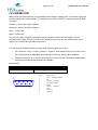
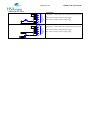
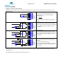
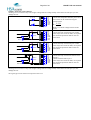
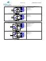
HSA Systems ApS Page 51 of 61 HSAJET-CU user manual Output 1 Active low (open collector) Warning: Do not connect a relay with a higher voltage than the voltage already connected to the VIO pin1 you will damage the unit. LED indicator 1 VIO R VALUE 6 IN1 Connect the components between pins 2 and 8 2 5V The R value can be calculated using the 7 12V 3 IN2 equation below 8 OUT1 4 9 5 1N4001 DIODE RELAY 1N4001 DIODE 3-33VDC EXTERNAL SOURCE 1N4001 DIODE GND EXTERNAL SOURCE STSW OUT2 GND R 5 Ud Id Where Ud is diode voltage and Id is diode current 5V DC relay Connect the relay coil between pins 2 and 8 Some relays have a built in diode, if not please also mount the protection diode on the coil connections. 1 6 2 7 3 8 4 9 5 VIO IN1 5V 12V IN2 OUT1 STSW OUT2 GND 1 6 2 7 3 8 4 9 5 VIO IN1 5V 12V IN2 OUT1 STSW OUT2 GND 12V DC relay Connect the relay coil between pins 7 and 8 Some relays have a built in diode, if not please also mount the protection diode on the coil connections. 1 6 2 7 3 8 4 9 5 VIO IN1 5V 12V IN2 OUT1 STSW OUT2 GND 3-33V DC relay with external power source Connect the relay coil between external VCC and pin 8 Connect external GND to pin 5 Some relays have a built in diode, if not please also mount the protection diode on the coil connections. Warning: Do not connect a relay with a higher voltage than the voltage already connected to the VIO pin1 you will damage the unit. The signal type can be selected in setup menu on the CU.