1
X100
Digital Video Recorder
and Product Family
Instruction Manual
© 11th August 2005 [V1.51m]
X100
Digital Video Recorder
and Product Family
Instruction Manual
CONTENTS
Contents..................................................................................................................................... 2
System Overview ....................................................................................................................... 5
X100 Digital Video Recorder ...................................................................................................... 6
Installation............................................................................................................................ 7
Mounting Diagram ......................................................................................................... 7
Rear Panel .................................................................................................................... 8
Front Panel....................................................................................................................9
Connector Specifications ............................................................................................. 10
Alarm Connector, Din Connector .......................................................................... 10
X100 Modem Connector ....................................................................................... 10
X100 RJ45 (Reviewer) Connector......................................................................... 10
Cable Specifications .................................................................................................... 11
X100 RJ45 Reviewer Socket to PC Cable ............................................................ 11
X100 Modem Socket to GSM/PSTN Modem Cable .............................................. 11
X100 to Reviewer Cable ....................................................................................... 11
Anti-Vibration Kit (T406)..................................................................................................... 12
Programming ..................................................................................................................... 16
Help Screens ..................................................................................................................... 16
Software Updates .............................................................................................................. 17
X100 & Hard Disk Cartridge LED Indicators ...................................................................... 18
Operation ........................................................................................................................... 21
Playback & Recording ................................................................................................. 21
Camera Switcher ......................................................................................................... 22
Zoom, Search and Help............................................................................................... 23
Jump to Time............................................................................................................... 24
File System ........................................................................................................................ 25
Loop Recording ........................................................................................................... 25
Single Pass Recording ................................................................................................ 25
Example - day long files .............................................................................................. 26
Example - hour long files ............................................................................................. 27
Example - 10 minute files ............................................................................................ 28
Write-Protection........................................................................................................... 29
Putting footage back onto an X100.............................................................................. 30
JPEG Compression ..................................................................................................... 31
PC Access Precautions ............................................................................................... 31
Permitted on a PC................................................................................................. 31
Not Permitted on a PC .......................................................................................... 31
Permitted with Caution on a PC ............................................................................ 31
2
Watermark ......................................................................................................................... 32
Watermark Definition ................................................................................................... 32
Accessing Watermark.................................................................................................. 33
Watermarks and PCLink Split Utility ............................................................................ 33
Hard Disk Cartridge ........................................................................................................... 33
Thermal Design ................................................................................................................. 34
Forced Ventilation Within Enclosures .......................................................................... 34
Low Temperatures....................................................................................................... 35
The Menu System ................................................................................................................... 36
Help Screens............................................................................................................... 36
Default Settings ........................................................................................................... 36
Menu Navigation ......................................................................................................... 37
Main Menu................................................................................................................... 38
Normal Recording Menu.............................................................................................. 39
Recording time, disk size and recording rate......................................................... 41
Timer Recording Menu ................................................................................................ 42
Timer Menu ................................................................................................................. 43
Alarm Recording Menu................................................................................................ 44
Recording History (Files) Menu ................................................................................... 46
File Listing............................................................................................................. 46
Voluntary Write-Protection .................................................................................... 46
Jump to File .......................................................................................................... 46
Alarm Input Menu ........................................................................................................ 47
Alarm Output Menu ..................................................................................................... 48
Video Switcher Menu................................................................................................... 49
Other Menus................................................................................................................ 50
Password Menu........................................................................................................... 51
Hints...................................................................................................................... 51
Examples .............................................................................................................. 52
Monitor Menu .............................................................................................................. 53
Camera Text................................................................................................................ 54
Current Date Menu ...................................................................................................... 55
Statistics Menu ............................................................................................................ 56
Advanced Menu .......................................................................................................... 57
Low Power Standby Mode .................................................................................... 57
File System Menu........................................................................................................ 60
Check Files Menu........................................................................................................ 62
Reset System Menu .................................................................................................... 63
SMS Message Menu ................................................................................................... 64
Sending emails via a gateway............................................................................... 66
X101 Reviewer......................................................................................................................... 67
Mounting Diagram.............................................................................................................. 68
Operation ........................................................................................................................... 69
Camera Tester................................................................................................................... 69
Using the X201 Reviewer with the X100 ............................................................................ 70
Accessing / Storing Images ...................................................................................................... 72
PCLink V2.21..................................................................................................................... 72
Introduction.................................................................................................................. 72
V2.21 enhancements over V2.1 .................................................................................. 72
Minimum Requirements............................................................................................... 72
Installation ................................................................................................................... 73
Starting PCLink ........................................................................................................... 73
Installing Cartridge....................................................................................................... 73
PCLink v2.21 Quick Reference.................................................................................... 74
Operating PCLink ........................................................................................................ 75
Camera Buttons .................................................................................................... 75
Camera Display Mode Buttons.............................................................................. 76
3
Camera Windows.................................................................................................. 76
Zoom..................................................................................................................... 76
Play Controls......................................................................................................... 76
Timeline Selectors................................................................................................. 77
Timeline Marker Flags........................................................................................... 77
Video Information Panel ........................................................................................ 78
Speed Control ....................................................................................................... 78
Watermarks........................................................................................................... 78
Password .............................................................................................................. 79
File Transfer ................................................................................................................ 79
Pasting Image to Art Package ..................................................................................... 80
RemoteLink V1.1.2 ............................................................................................................ 81
Introduction.................................................................................................................. 81
Overview ..................................................................................................................... 81
Hardware Required ..................................................................................................... 82
Specification of Cabling ............................................................................................... 82
RJ12 Power Cable ................................................................................................ 82
RS232 Serial Cable............................................................................................... 82
Installation ................................................................................................................... 83
1 Configure the SIM card ..................................................................................... 83
2 Insert SIM card into modem .............................................................................. 84
3 Load V1.5 software onto X100 system.............................................................. 84
4 Connect modem equipment .............................................................................. 84
5 Install Remote Link V1.1.2 onto PC................................................................... 84
Running RemoteLink ................................................................................................... 85
Selecting a modem...................................................................................................... 86
Entering / managing phone numbers........................................................................... 87
Contacting a remote unit ............................................................................................. 88
Remote operation ........................................................................................................ 89
Removing RemoteLink ................................................................................................ 89
OBA to AVI File Converter V1.1.2...................................................................................... 90
Introduction.................................................................................................................. 90
Usage.......................................................................................................................... 90
Transferring Files to PC ..................................................................................................... 92
USB Interface Kit (T403-USB) ..................................................................................... 92
FRAME Interface Kit (T403-FRM)................................................................................ 92
Transferring Images to Video Tape.................................................................................... 92
Appendix .................................................................................................................................. 93
Safety ................................................................................................................................ 93
X100 EMC Conformity (CE Mark) ...................................................................................... 93
X100 EMC Conformity (E Mark)......................................................................................... 93
X100 EMC Conformity (Specification 5)............................................................................. 94
Guarantee.......................................................................................................................... 94
Specifications..................................................................................................................... 95
X100 Digital Video Recorder ....................................................................................... 95
Removable Hard Disk Cartridge .................................................................................. 96
X101 Reviewer ............................................................................................................ 96
Troubleshooting ................................................................................................................. 97
Error Messages and Other Messages ......................................................................... 97
Possible Problems and FAQ's ................................................................................... 100
X100 ................................................................................................................... 100
X101 ................................................................................................................... 100
T406.................................................................................................................... 101
4
SYSTEM OVERVIEW
The X100 is a digital video surveillance recorder for use in covert, portable and mobile
applications.
Recordings are made on a removable hard disk cartridge inserted in the X100. After the hard
disk cartridge has been removed, the recordings can be accessed by connecting the cartridge
to a PC, using either USB or Frame Interface Kits, which includes PCLink, a proprietary reading
and archiving software package.
The use of Hard Disk Cartridges other than those supplied by Timespace Technology
will invalidate the warranty of the X100 recorder, and will constitute a breach of the X100
operating software copyright.
The X101 Reviewer is used to program the menu settings on X100, to check camera views and
to review recordings on the installed X100 hard disk cartridge. Recording will continue during
this reviewing process.
The X100 and X101 are available in either PAL or NTSC models.
The 24-hour clock is used for all times and settings.
WARNING: The X100 Recorder must always be mounted so that there is a free flow of air
around it. If it is mounted in an enclosure, it is essential that adequate ventilation is
provided, and it is recommended that a fan is incorporated in the enclosure design.
WARNING: If the X100 Recorder is mounted in a vehicle, or otherwise subject to
vibration, suitable damping must be built into the mounting.
WARNING: Hard disk cartridges are sensitive to shock, vibration and humidity.
5
X100 DIGITAL VIDEO RECORDER
6
Installation
The X100 can be used free-standing or it can be mounted on a wall or bulkhead.
Power can be applied to X100 either via 12V DC jack socket (use PSU supplied with X100), or
12V screw terminals. NB: Do not use both power inputs simultaneously.
The Hard Disk Cartridge (supplied separately) with lock on the front in "Off" position should be
inserted into receptacle in front panel of X100 and gently but firmly pushed into place, then lock
switched to "On" position.
Mounting Diagram
4 x threaded holes are available in the back panel of the X100 for mounting:
7
Rear Panel
Video Out
Video In (BNC)
Video In (DIN)
DC Power Socket
DC Power terminals
Alarm Inputs
Alarm Output
Modem
For connection to external monitor
Connect cameras 1 to 4 to these sockets
Connect cameras 5-8, using 5 pin 180° DIN locking plug
(Deltron part 590-0500; Farnell order code 590-0500).
For PSU supplied only (use DC power terminals where possible)
1 x pair screw terminals to be used in preference to Socket
4 x pair screw terminals (cameras 1 to 4 only)
1 x pair screw terminals
For connection to GSM modem
8
Front Panel
Main Bay
On/Off
Power LED
Recording LED
Disk Status LED
Reviewer
Insertion of hard disk cartridge
Power to X100 (menu enabled)
Flashing in low power standby mode,
On all the time for normal operation
On when recording
On when disk full (applies to single pass recording only)
Connection to X101 Reviewer (power, video and keypad control)
9
Connector Specifications
Alarm Connector, Din Connector
8
5
6
7
GND
DIN SOCKET
CONNECTIONS
(looking at rear panel)
Video inputs 5 to 8
X100 Modem Connector
Arranged as per IBM PC 9 pin serial port. The connector is a 9 way D-Type female connector.
1
2
3
4
5
6
7
8
9
DCD
RD
TD
DTR
GND
DSR
RTS
CTS
RI
IN/OUT
IN
IN
OUT
OUT
IN
OUT
IN
not connected within X100
X100 RJ45 (Reviewer) Connector
The pin configuration of the RJ45 connector is proprietary. It must not be connected to an
Ethernet network.
Pin 1 is the pin closest to the centre of the X100 front panel.
1
2
3
4
5
6
7
8
Video Out
Use 1 and 2 for Video Out
GND
GND
RD
IN
(serial connection RS232)
TD
OUT
(serial connection RS232)
Reviewer detect, pulled up to 5V internally. Connect to GND for Reviewer
GND
3 and 7 power / RS232 ground
+12V DC output
This is directly connected to the +12VDC input on the X100
10
Cable Specifications
X100 RJ45 Reviewer Socket to PC Cable
This cable is used to connect a PC to the X100 RJ45 (Reviewer) socket.
9 way D-Type female connector to RJ45 plug.
[Typically use a standard CAT5 cable [EIA/TIA 568B wiring standard (straight 1-8 to 1-8
connection)] and cut and wire onto the D type connector]
Connect pins as follows:
RJ45 Cable
Modem Plug
1
White with orange stripe
2
Orange (with white stripe)
3
White with green stripe
Pin 5
4
Blue (with white stripe)
Pin 3
5
White with blue stripe
Pin 2
6
Green (with white stripe)
7
White with brown stripe
Pin 5
8
Brown (with white stripe)
Cable wires 1, 2, 6 and 8 can be cut back (not connected)
X100 Modem Socket to GSM/PSTN Modem Cable
9 way D-Type female to 9 way D-Type male connectors.
Connect all pins straight through
1-1
2-2
3-3
4-4
5-5
6-6
7-7
8-8
9-9
X100 to Reviewer Cable
Standard CAT5 cable (shielded) [EIA/TIA 568B wiring standard (straight 1-8 to 1-8 connection)]
11
Anti-Vibration Kit (T406)
Please adhere to the following instructions for the installation of the Anti-Vibration Kit. Failure
to do so may result in the Mounting System not working correctly.
Section A – Inventory Of Parts
The Anti-Vibration Kit consists of the following parts QTY
4
1
8
Description
Wire Rope Mounts
Stabiliser Coupling
Zinc Plated M4 x 10mm Counter-Sunk Hex-Head Screws.
In addition you will require a standard ‘L’ shaped hex key. This is essential, as when all of the
other screws have been tightened, there is no room for any other tool to tighten the front lower
pair of screws.
Section B - Mounting Surface/Enclosure Preparation
Mounting Hole Preparation
Drill four mounting holes to attach the Wire Rope Mounts. If you intend to use the M4 x 10mm
screws into blind holes, then the holes will have to be drilled and tapped to accept an M4
screw, with a thread depth of no less than 8mm.
If mounting the Wire Rope Mounts through a metal plate, then longer screws may have to be
used in order to allow a washer and nut to be attached on the other side of the plate. The
length of these screws will have to be chosen depending on the thickness of the plate and the
height of the washer and nut.
Please note that any screw used for mounting the wire rope mounts to an enclosure surface
must have an M4 thread and have a counter-sunk hex-head.
Please refer to Diagram B1 for details of blind and through-hole mounting.
Diagram B1
Mounting Hole Location – X100
The mounting holes must be drilled on 126mm and 88mm centres. This is shown in diagram
B2.
12
Diagram B2
Total Mounting Volume Required – X100
It is necessary to allow a minimum clearance of at least 10mm around the body of the X100
when mounted on the T406 Anti Vibration Kit. This is to allow free movement of the X100 on
the anti vibration mounts and to prevent collision with either the enclosure or peripheral
systems due to vertical and lateral movement under extreme shock and vibration conditions.
Please refer to diagram B3 for exact dimensions.
Diagram B3
Please note that when installing cables to the rear of the X100 it is important not to
arrange or clamp them in such a way as to impede the free movement of the rear antivibration mounts. Please refer to diagram B4 on the following page.
13
Diagram B4
Section C - Installation Procedure
It is advised that some form of thread-lock compound should be used on the screws
securing the wire rope mounts to both the X100 and mounting surface. This is in order
to prevent loosening due to vibration.
1)
Attach the Wire Rope Mounts to the X100 with four of the countersunk M4 hexhead screws provided and L-shaped hex key. When attaching the rear pair of
mounts please ensure that the stabilizer is ‘sandwiched’ between the mounts and
the X100 by aligning the stabilizer holes with the mounting holes in the X100.
Please refer to diagram C1.
Please note that the ‘open’ end of the C-shaped plastic stabiliser should be attached to
the rear wire rope mounts and face backward as shown in diagram C1.
2)
Once all of the Wire Rope Mounts have been securely attached to the X100, use a
pair of countersunk M4 hex-head screws to attach the bottom ‘feet’ of the front
Wire Rope Mounts to the mounting surface/enclosure.
3)
Secure the lower ‘feet’ of the rear Wire Rope Mounts to the mounting
surface/enclosure using the remaining pair of countersunk M4 hex-head screws
and a standard L-shaped hex key. Ensure that the stabilizer is ‘sandwiched’
between the lower feet and the mounting surface/enclosure by screwing through
the Wire Rope Mount feet, then the stabilizer and into the mounting
surface/enclosure.
Diagram C1
14
Orientation of Unit
The X100 should be mounted in the following horizontal orientation as per diagram C2.
This is strongly advised for maximum vibration and shock isolation.
Diagram C2
If it is not possible to mount the X100 in the horizontal orientation then the following vertical
orientation as detailed in diagram C3 may be used.
It must be noted however that this vertical orientation is not as effective at isolating the
X100 from vibration and shock as the horizontal orientation as shown in diagram C2.
The position of the plastic stabiliser, screw types and assembly order remain the same for this
mounting orientation.
The X100 must never be mounted by hanging it upside down from a horizontal surface when
using this mounting system.
Diagram C3
15
Programming
The configuration of the X100 is by the menu system.
Connect Data Link Cable (supplied with X101 Reviewer) from socket marked "Reviewer" on
X100 to socket marked "To Recorder" on X101. This connection will provide power and video
to X101 from X100.
WARNING: When X101 is connected to X100 the power supplied to X100 must be 12V+/1.2V. An additional PSU can be connected to "Power In" socket of X101, but to view
X100 a BNC cable must be linked from "Out" socket on rear panel of X100 to "Video In"
socket on top panel of X101.
To enter Menu System press
menu key.
Help Screens
Throughout the menu system, every item that the cursor points to has a Help screen. Place the
cursor on the line requiring explanation and press "Help" key on X101 front panel. Use any
key to cycle through the screens for that line. No Help screen is available for Statistics Menu.
16
Software Updates
Occasionally software improvements are made to X100 and a new version of software is made
available. Follow these steps to download new software:
Ensure X101 Reviewer is not connected to X100 Recorder.
Connect serial link cable from "Reviewer" socket on X100 front panel to serial port on PC.
With hard disk cartridge inserted and switched on, hold in "On/Off" button on front panel of
X100 then connect power to X100. Release On/Off button. All three LED's on X100 front panel
should now be illuminated. Alternately, maintain power to X100, and switch off hard disk
cartridge. Hold X100 On/Off button in and switch on hard disk cartridge.
When all three LED's on X100 front panel illuminated, the Recorder is ready for download.
NB: Full reset will delete all existing recordings on hard disk.
Wait 40 seconds after download until LED on hard disk cartridge changes from amber to green.
17
X100 & Hard Disk Cartridge LED Indicators
The following section describes the normal operation of the front panel LED indicators on the
X100 and hard disk cartridge. It may be useful in order to confirm normal operating conditions
and situations where a problem may have occurred.
X100 With Hard Disk Cartridge Inserted
1) When an external 12V DC power supply is connected to the X100.
i)
The ‘Power’ LED will illuminate to indicate that 12V DC power is being supplied to the
X100 via either of the rear panel inputs. The ‘Power’ LED will remain illuminated until
the power supply is removed or the unit is placed into low power standby mode as
detailed in section 4 following.
If the ‘Power’ LED is dim and/or the hard disk cartridge does not follow the sequence as in
section 2 following, then there may be insufficient voltage to supply the X100.
Please note that the X100 and hard disk cartridge require a 12V +/-1.2V DC power supply.
2) When a hard disk cartridge is inserted and switched on.
i)
ii)
The hard disk cartridge LED will illuminate green and flash amber intermittently as
operating code is loaded into X100.
The ‘Recording’ & ‘Disk Status’ LED’s will illuminate simultaneously for approximately 1
second and then switch off.
3) Whilst recording.
i)
ii)
The ‘Recording’ LED will illuminate and remain lit for the duration of the recording.
The hard disk cartridge LED will remain illuminated in green but will intermittently flash
amber as data is recorded to the hard disk. The frequency of the amber flashes will
depend on the chosen recoding parameters.
18
4) When the unit is placed in low power standby mode.
In the default setting the X100 is placed into low power standby mode by pressing the front
panel ‘On/Off’ button whilst the unit is in normal operating mode.
This feature may be software configured by accessing the menu system via the X101 reviewer.
To change the low power standby mode setting, go to ► Other Menus ►Advanced, and use
the ‘Pushbutton Switches’ option. The various options are detailed in the ‘Low Power Standby
Mode’ section of the manual.
i)
ii)
iii)
The ‘Power’ LED will flash intermittently.
The hard disk cartridge LED will switch off.
The ‘Recording’ LED will switch off and recording will cease if the X100 is placed into
low power standby mode whilst recording.
Please note that the X100 will switch back to normal operation from low power standby mode if
the front panel ‘On/Off’ switch is pressed, the X101 reviewer is attached or the state of an alarm
input changes.
Low power standby mode is not accessible unless a hard disk cartridge is inserted and
switched on.
5) If the ‘Disk Status’ LED is illuminated.
The ‘Disk Status’ LED indicates one of the following conditions.
i) The hard disk cartridge is full of write-protected files.
In this situation an attached X101 will show the current camera output determined by the video
switcher, and the menu system will be accessible as per normal.
The hard disk cartridge will be full due to the options in the X100 ‘File System’ menu having
been set to write-protect certain types of recordings (any combination of Normal, Timer &
Alarm). The X100 will not re-record (Loop recording) over write-protected recordings and will
therefore not make any new recordings once the disk is full of write-protected recordings
(Single pass recording).
In order to change the write-protection settings, access the X100 menu with the X101 reviewer
and go to ► Other Menus ► File System. At the top of the ‘File System’ menu is ‘Write
Protection For’. Write-protection can then be enabled or disabled for each type of recording as
required.
Please refer to the ‘File System’ section in the manual for more details on which settings to use.
Please note that in its default setting the X100 automatically write-protects Alarm recordings but
not Normal or Timed recordings.
ii) If it has been established that the hard disk cartridge is not full of write-protected files.
In this case the illumination of the ‘Disk Status’ LED may indicate that the operating code was
not loaded from the hard disk cartridge to the X100 correctly when the external 12V DC power
supply was last connected and the hard disk cartridge switched on.
In this situation an attached X101 will show ‘snow’ on the screen and the menu system will not
be accessible.
In order to reset the system and reload the operating code, either switch the cartridge to the off
position and wait at least 5 seconds before switching back on or disconnect the external power
supply from the X100 and wait at least 5 seconds before reconnecting.
19
If the ‘Disk Status’ LED remains illuminated after reset, then the operating code on the hard
disk cartridge may be corrupted, there may be corrupted recording files on the disk or the hard
disk itself may be damaged.
If the ‘Disk Status’ LED remains illuminated after resetting the system as described previously,
then please contact the equipment supplier.
6) If the ‘Recording’ & ‘Disk Status’ LED’s flash twice, instead of once, when the hard
disk cartridge is switched on.
If this occurs instead of the usual sequence as described in section 2 previously, then the X100
has entered a mode reserved for Timespace Technology engineers to adjust factory settings.
To exit this mode, either switch the cartridge to the off position and wait at least 5 seconds
before switching back on or disconnect the external power supply from the X100 and wait at
least 5 seconds before reconnecting. If the same situation reoccurs after the external 12V DC
power supply has been reconnected, then please contact the equipment supplier.
7) If the ‘Recording’ & ‘Disk Status’ LED’s remain illuminated when the hard disk
cartridge is switched on.
If this occurs it indicates that the hard disk cartridge is ready to download new operating
software. Please refer to the ‘Software Updates’ section in the manual for the correct
procedure for downloading software to a hard disk cartridge.
If this state has been triggered accidentally, either switch the cartridge to the off position and
wait at least 5 seconds before switching back on or disconnect the external power supply from
the X100 and wait at least 5 seconds before reconnecting. This will re-start the X100 and hard
disk cartridge in normal operating mode.
20
Operation
To set up and operate the X100 an X101 Reviewer is required.
Playback & Recording
Rewind through recorded footage. The normal wind interval is 1 minute. Pressing the
button again increases the wind interval to 5 minutes. Repeated presses increase the
interval to 10 / 20 and finally 60 minutes. This rapid scan mode enables fast, flickerfree searching through recorded material. If the LED above the stop button is lit the
unit is in jog mode and the rewind button will rewind through recorded footage frame by
frame, with intervals of 1 minute.
Reverse-play through recordings. If the LED above the stop button is lit (jog mode),
the reverse-play button will jog to the previous frame. If the oldest frame has been
reached, reverse playback will stop. Note that reverse play only operates on images
that have been first played in a forward direction.
Stop playback. If playback is already stopped, pressing this button again lights the LED
above and the unit is in jog mode, allowing frame-by-frame playback.
Play recorded footage. Pressing play for a second time switches to fast play enabling
all the footage to be played through at the fastest rate. If the LED above the stop button
is lit, the play button will jog to the next frame. If the most recent frame has been
reached, playback will stop.
Fast-forward through recorded footage. If the LED above the stop button is lit the unit
is in jog mode and pressing the fast-forward button will jog forward. Similarly to rewind,
repeated presses of the fast forward enable rapid scan in 5 / 10 / 20 / 60 minute
intervals.
Record start or stop. If not currently recording (red LED off), pressing this button will
begin recording from the end of the most recent footage, using the settings specified in
the Normal Recording menu (see page ). If the unit is currently recording (red LED on),
this button will stop recording.
21
Camera Switcher
1-8
Switch the view to camera 1 to 8. When playing back recorded footage, pressing
buttons 1 to 8 changes playback to that camera. If the AUTO LED is lit, buttons 1
to 8 change the live camera being viewed. This camera is held on the main
monitor.
AUTO
Activate the auto switcher mode. In this mode, the monitor will show a live view
and the cameras are cycled as specified in the "Video Switcher" menu. Press the
AUTO button again to deactivate the auto switcher mode. If any of the buttons
numbered 1-8 are pressed while in auto switcher mode, the camera switching is
stopped, and the selected camera view is held on screen.
DELETE
When using menus this button is used to delete numbers.
Control of the auto switcher does not affect any recording in progress.
22
Zoom, Search and Help
ZOOM
Zoom in on a frame from recorded footage (in black & white). Use the menu
navigation buttons (see next page) to pan around the enlarged image. Press the
ZOOM button again to return to original size. When the zoom function is active,
the ZOOM button will be lit.
HELP
Applies when using any menu. Pressing this button will produce a help screen.
Continue pressing any key to cycle through help screens until menu returns.
SEARCH
Go to a specific time and date in the recorded footage. Pressing this button will
enter the "Jump to Time" screen. If the footage on a given camera cannot be
found (it may not have been recorded), a "NO CURRENT IMAGES ON CAMERA"
message will be displayed. If there is no footage at the time specified a jump is
made to the nearest footage to the time given.
See the next page for further information on Jump to Time.
MOTION
This key is reserved for future use.
23
Jump to Time
JUMP TO TIME
-----------TIME: >14:45:00
DATE: >17/08/98
>JUMP TO TIME ABOVE
>JUMP TO OLDEST
>JUMP TO LATEST
EXIT
This is the "Jump to Time" menu, which is displayed after pressing the SEARCH button, and
allows instant access to any time (on the minute) and date in recorded footage.
•
TIME - Type a time using the numbered buttons.
•
DATE - Type a date using the numbered buttons.
•
JUMP TO TIME ABOVE - Hit the right arrow menu key to jump to the time entered in the
time and date fields.
•
JUMP TO OLDEST - Jumps to the oldest recordings on disk.
•
JUMP TO LATEST - Jumps to the newest recordings on disk.
If the footage cannot be found for a particular camera (the camera may not have been
recording at that time / date), a NO CURRENT IMAGES ON CAMERA "n" message will be
displayed ("n" being the selected camera view).
If there are no recordings available at a current time specified the JUMP TO TIME function will
jump to the nearest available footage. A jump can only be made to a full image and the JUMP
TO TIME function will jump to the nearest available full image (key frame).
You must use leading zeros for the time and date where necessary, e.g. 09:45 and 04/07/98.
24
File System
Any disk removed from the X100 recorder can be viewed on a PC and recording files
(proprietary format .oba files) are displayed. The disk can be connected to the PC using two
interfacing methods:
Interface
1 IDE/USB
2 IDE (ATA)
Details
Easy connection; 12Mbit/sec transfer
rate is adequate for PCLink playback
Disk is inserted into PC
fastest data rate, but technical PC knowledge
required to install frame.
Product code
T403-USB
T403-FRM
Once the disk has been connected, the disk shows up as a drive letter (typically D:) on the PC.
Recording files can be viewed using Windows Explorer and three examples are given on the
next pages.
Loop Recording
By selecting no write-protection on the recorder:
FILE SYSTEM
----------WRITE PROTECTION FOR:
NORMAL RECORDING: >NO
TIMER RECORDING:
NO
ALARM RECORDING:
NO
it automatically loops deleting oldest recordings first. The record position is stored and any play
back will not affect the current record position (this is in contrast to a VHS tape).
Single Pass Recording
By selecting full write-protection on the recorder:
FILE SYSTEM
----------WRITE PROTECTION FOR:
NORMAL RECORDING: >YES
TIMER RECORDING:
YES
ALARM RECORDING:
YES
it records until it is full and then stops. The disk status LED is lit when it is full. Files may be
un write-protected to free up space or else the recordings may be deleted in the RESET menu.
Write-protection can be used to keep Alarm recordings but loop the background (Normal)
recording.
25
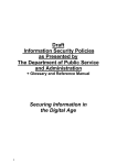
Example - day long files
In the above example the contents of the X100 hard disk cartridge are displayed (D:). 12 files
have been recorded one for each day from 7th Aug to 18th Aug. Before this recording period and
within this recording period 4 alarm events were generated and these are stored in event files
"ALARM …. .oba" . Alarm events have been automatically write-protected (R character
meaning READ ONLY) and will never get overwritten by the recorder. The other non writeprotected files are overwritten oldest first in a looping manner automatically by the recorder.
The FILESYSTEM menu on the X100 (OTHER MENUS -> FILE SYSTEM MENU) controls the
way the files are written to the hard disk. Please see the Menu System chapter for more
details. The above disk was generated using the following menu settings:
FILE SYSTEM
----------WRITE PROTECTION FOR:
NORMAL RECORDING: >NO
TIMER RECORDING:
NO
ALARM RECORDING:
YES
FILE LENGTH FOR:
NORMAL / TIMER
RECORDING:
ALARM RECORDING:
1 DAY
EVENT
26
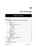
Example - hour long files
In the above example the contents of the X100 hard disk cartridge are displayed (D:). 16 files
have been recorded one for each hour. Recording started at 14:15:34 on August 19th and
carried on till 05:06:23 on August 20th. The time shown indicates the start time of the file
(ignoring the seconds). If the user stopped recording during any hour and then started
recording again in that hour, the information would be included in the single hour file. 4 alarms
were also triggered over the recording period but the alarm recording has automatically been
included in the hour files (file length for alarm recording was not set to EVENT but to the same
setting as Normal / Timer recording, in this case 1 HOUR)
This example indicates how alarm triggered recordings can be grouped together into hour long
files. Alarm recordings can be grouped together into 10 minute files or day long files as
selected in the File System menu. The following menu settings were used on the recorder:
FILE SYSTEM
----------WRITE PROTECTION FOR:
NORMAL RECORDING: >NO
TIMER RECORDING:
NO
ALARM RECORDING:
NO
FILE LENGTH FOR:
NORMAL / TIMER
RECORDING:
ALARM RECORDING:
1 HOUR
1 HOUR
27
Example - 10 minute files
In the above example the contents of the X100 hard disk cartridge are displayed (D:). 12 files
have been recorded covering a period from 9:02:15am to 10:55:12am. Within this recording
period 4 alarm events were generated and these are stored in the event files "ALARM ….
.oba" . No write-protection has been selected for the alarm recording or normal recording so
the oldest files will be overwritten first.
The following menu settings were used on the recorder:
FILE SYSTEM
----------WRITE PROTECTION FOR:
NORMAL RECORDING: >NO
TIMER RECORDING:
NO
ALARM RECORDING:
NO
FILE LENGTH FOR:
NORMAL / TIMER
RECORDING:
ALARM RECORDING:
10 MINS
EVENT
Please refer to the Menu System chapter for further information of the above menu.
28
Write-Protection
Any file can be write-protected or un write-protected on the X100 or the PC. The recorder will
not overwrite write-protected files. To change the protection of a file on the X100 please see the
menu section of the manual. To change the protection on the PC, right click on the file and
select properties. Then tick or untick the Read-only flag of the file. Read-only (R) corresponds
to Write-protected (W) in the X100 recording history menu. If a file is write-protected on the
PC, and the disk is re-inserted back into the recorder, the recorder will treat it as write-protected
and not overwrite it.
Right click file and select file properties
Change the read-only flag as required.
29
Putting footage back onto an X100
In certain circumstances it may be necessary to put files back onto a cartridge so that they may
be replayed by the X100. The following steps should be taken:
1 Put cartridge in an X100 and run a full reset (menu and recordings)
2 Connect disk via USB to PC (not forgetting to unplug and plug the USB connector as a last
step in the connection for each disk). The PC should pick up the disk containing two hidden
files SYSTEM and SYSTEM_B
3 Run Scandisk on the drive. This corrects the free disk size (which shows full on Windows
98, ME, XP) and allows files to be copied to the disk. To run scandisk right click the disk drive
letter of the cartridge (in the picture below the D: on the left hand side) then going to Properties>Tools->Check Now->Scandisk and using a Standard Test press start. Correct the single error
message that appears (reported free space not correct).
4 Drag the source .oba file(s) into the disk as shown below.
The disk will now be playable on the X100.
Dragging a file into D: the X100 cartridge
30
JPEG Compression
The JPEG standard and corresponding file extension .jpg is designed for single images. The
X100 uses JPEG compression to store images but requires the storage of multiple images and
also the incorporation of conditional refresh. The proprietary .oba file extension is used to
encompass these additional requirements and the resultant file type is proprietary. The
following summarises the .oba file format:
1 JPEG compression algorithm
2 JPEG blocks omitted as required to encompass conditional refresh
3 Multiple full or conditional images written back to back
4 Additional information such as watermark data and control information is incorporated into
the protocol.
PC Access Precautions
It is important to understand that the X100 filesystem is a subset of the PC FAT32 filesystem.
The PC will access the X100 disk cartridges with no problems but the X100 will not be able to
read every FAT32 filesystem written by the PC.
Permitted on a PC
Reading the .oba files
Modifying the write-protect status of files
Performing disk utilities that read the disk (e.g. Scandisk but do not modify disk)
Not Permitted on a PC
All write accesses to the disk if it is to be reused in an X100. These include:
Formatting the disk on PC
Defragmenting the disk
Deleting system and system_b hidden files
Deleting other files
Renaming files
Generating new files
Creating a recycle bin on the disk
Permitted with Caution on a PC
The process of putting files back onto the disk for playback on X100 as described in the
previous section.
31
Watermark
The disk is divided into files. Each file consists of a number of image sets and for each image
set there is a block of attached information. A pictorial example of two files is shown below:
File 1 "28 Jan 2002 time 12:00;00.oba" containing:
Image set 1
Information about images set 1
Image set 2
Information about images set 2
Image set 3
Information about images set 3
……
Image set 60
Information about images set 60
File 2 "28 Jan 2002 time 13:00;00.oba" containing:
Image set 1
Information about images set 1
Image set 2
Information about images set 2
……
Image set 60
Information about images set 60
A new image set is created at the interval selected by the menu option shown below which is
typically 1 minute:
FULL UPDATE EVERY:
1 MIN
The information block holds amongst other things a watermark for the image set.
Watermark Definition
The X100 uses a fragile watermark. Any modification to the image data e.g. changing faces,
lighting, contrast or other modifications will destroy the watermark. The image data that makes
up the image set is passed though a function that generates a "magic number" or hash code
from the images. The terms hash code and watermark are synonymous. A hash code is
created automatically by the X100 for each image set and is stored in the information block.
The hash code is a number between 0 and 1.84 x 10^19 (i.e. 18.4 million million million) (64 bit
number) . The hash code can be regenerated at any time by passing the image data back
though the function (i.e. in a watermark checking program). If the hash code thus obtained
matches the hash code stored in the information block, the image data has not been altered or
modified in any way. The watermark is "destroyed" when the hash code stored in the
information block and the hash code of the data do not match.
32
Accessing Watermark
When reviewing recordings made on the X100 digital video recorder, the fragile watermark can
be displayed to prove the images have not been tampered with.
The hard disk cartridge is removed from the X100 digital recorder. The cartridge is connected
to a PC via USB port. Proprietary software called PCLink (freely available to Police forces) is
used to access the recordings (a password can be entered to prevent unauthorised access),
and a menu option activates and de-activates the display of the watermark. A valid watermark
is shown as a green "W", whereas an invalid watermark is displayed as a red "W" with an "X"
through the symbol.
Watermarks and PCLink Split Utility
A single archive can be extracted from a long file or multiple files using the PCLink software on
a PC ("save video between markers" button). Watermarks are left intact as PCLink splits off
images in minute multiples and the watermark for each minute is also copied to the new file.
See above for verifying the watermarks.
Hard Disk Cartridge
The X100 records onto a 2.5" IDE hard disk contained in a cartridge (T401-series).
The cartridge contains custom electronics. All menus and software are stored on the hard disk.
Only T401-series hard disk cartridges can be used with the X100.
The use of Hard Disk Cartridges other than those supplied by Timespace Technology
will invalidate the warranty of the X100 recorder, and will constitute a breach of the X100
operating software copyright.
WARNING: Hard disk cartridges are sensitive to shock, vibration and humidity.
33
Thermal Design
The X100 may be operated in ambient temperatures from 5°C to 40°C. This specification
applies in still air, with the X100 mounted horizontally and ambient temperature measured at
15cms above the centre of X100.
If the X100 is to be mounted in an enclosure is important that the internal temperature inside
the enclosure does not exceed the specification above and any new enclosure design should
be tested. A simple but effective test is to place a thermocouple inside the enclosure and one
outside and measure the operating temperature difference. This difference must be deducted
from the X100 40°C maximum.
Example
Temperature outside enclosure 25°C
Temperature inside enclosure 35°C
Difference
10°C
Maximum inside enclosure
Maximum outside enclosure
40°C (X100 max)
30°C (40°C-10°C)
In the above example the 40°C max spec has been derated to 30°C due to the effect of the
enclosure.
Forced Ventilation Within Enclosures
It is advisable to include a fan integral to any enclosure design. The goal of the fan is to
remove air heated by the X100 and replace it by air at the outside temperature. The
temperature difference shown in the above example of 10°C can be reduced to a few degrees
using a small fan. Two small fans are typically better than one due to failsafe. Fans do need
checking periodically and can draw in large amounts of dirt and dust if air conditions are not
good. Dirt and dust should be removed periodically. To reduce dirt ingress a fan may typically
be run slower than rated by reducing the voltage from that specified. This can typically be done
with a single resistor in series with the fan. Alternatively air filters may be used but these
impede airflow and require careful system design. The X100 is limited from problems of dirt
ingress as it does not incorporate a fan but instead uses an internal switch-mode power supply
to reduce power consumption (and therefore heat).
Fans offer two immediate benefits:
1 Changing the air inside the case makes the air temperature inside the case within a few
degrees to that outside.
2 If the airflow is channelled around the top surface of the X100 so that air is draw particularly
over the two sides and the top, further thermal improvement is gained and an X100
specification of 5°C to 45°C may be used. (The difference between the surface X100 case
temperature and ambient temperature is typically 5°C and this is the extra maximum benefit)
34
Low Temperatures
Specific low temperature design normally goes hand in hard with providing a large thermal
range. Insulating the X100 (e.g. inside an enclosure) and leaving it powered up (but not
necessarily recording) will allow it to be used at sub zero temperatures. The insulation works
against the user as the outside temperature rises above 10°C. To offer the best performance in
low and high temperature environmental conditions, an insulated case can be used with a fan,
which is thermostatically controlled to switch on when the temperature rises above 10°C.
Better still, the fan speed can be ramped up and slowed down based of a thermal feedback
circuit (analogue thermostat).
35
THE MENU SYSTEM
The menu system is used to configure the X100 and gives control over recording resolution,
camera sequencing, timer settings and alarm triggering and alarm triggered recording. There is
also access to monitor options and password functions along with many other parameters.
A menu can contain the following types of entry:
• Sub-menu heading - press the right arrow menu key and the sub-menu is entered.
• Function - press the right arrow menu key and the function is performed (e.g. Reset
System).
• Selection - press the left and right menu keys to cycle through the choices.
• Numeric item - input numbers 0 to 9 on the keypad (e.g. entering a time) and use the DEL
button to correct mistakes.
Any changes made to the menu system have immediate effect on the operation of the system.
Any changes to a menu are stored after 3 seconds of no keys being pressed. The menu is
stored on the hard disk. To revert to the factory settings run a RESET MENU TO THE
FACTORY DEFAULT STATE function in the RESET SYSTEM menu.
All the menus listed are shown in their factory default state.
Help Screens
Every menu apart from the Statistics Menu, and every item within the menu has a separate
help screen. Place the cursor against the chosen item and press the HELP key. Cycle
through the pages of the help screens by using the right arrow menu key.
Default Settings
Factory default settings are used in the illustrations in the following section.
36
Menu Navigation
The menu system on the X100 can be accessed by using the X101 reviewer. Connect the
dedicated 8 way (Ethernet style) cable (supplied with X101) to the recorder and consult the
instructions for X101 Reviewer.
Press any of the 4 menu buttons to enter the main menu. Once in the menu system, their
function is as follows:
Move up to the next menu item. If the pointer is currently at the top of the menu, pressing
the up button will exit the menu.
Move down to the next menu item. If the pointer is currently at the bottom of the menu,
pressing the down button will exit the menu.
If the pointer is currently at a menu selection
(e.g. RESOLUTION: > HIGH),
pressing the left button will cycle the value backwards,
(e.g. to RESOLUTION: > MEDIUM),
If the pointer is currently at a menu selection
(e.g. RESOLUTION: > LOW),
pressing the right button will cycle the value forwards,
(e.g. to RESOLUTION: > MEDIUM).
If the pointer is currently at a sub-menu title
(e.g. > OTHER OPTIONS).
pressing the right button will enter this sub-menu.
If the left and right menu keys have no effect, then numerical entry using keys 0 to 9 is
required. The DELETE key can be used to delete numerical entries.
If the zoom function (note: monochrome zoom only) is active, the up, down, left and right
buttons pan around the enlarged image. The default position of the pointer is show on the
menu by the arrow character ">".
37
Main Menu
MAIN MENU
--------> NORMAL RECORDING
TIMER RECORDING
ALARM RECORDING
RECORDING HISTORY
ALARM INPUT
ALARM OUTPUT
VIDEO SWITCHER
OTHER MENUS
EXIT
Further sub-menus can be accessed here:
•
•
•
•
•
•
•
•
NORMAL RECORDING - default recording set-up activated by the record on/off button.
TIMER RECORDING - recording set-up activated by the inbuilt weekly interval timer.
ALARM RECORDING - recording set-up activated by the alarm inputs.
RECORDING HISTORY - lists the files stored on the hard disk and allows a jump to the file
in question. The write-protection (i.e. protection from deletion due to the disk looping round)
of any file can also be set or reset.
ALARM INPUT - sets the normally open / closed / inactive conditions for each of the 4
alarm inputs
ALARM OUTPUT - governs the operation of the alarm output relay.
VIDEO SWITCHER - allows the dwell times of the video switcher to be controlled.
OTHER MENUS - leads to the other menu items.
Use the up / down buttons to select a sub-menu and the right button to enter a sub-menu.
38
Normal Recording Menu
NORMAL RECORDING
---------------INTERVAL:
>MAX RATE
RESOLUTION: HIGH
FORMAT:
COND. REFRESH
FULL UPDATE EVERY: 1 MIN
ORDER: 1
EXIT
There are three recording modes:
• Normal Recording - This is triggered by pressing the
record button or is switched on
after timer recording (see timer menu).
• Timer Recording - This is active during or outside the working hour times of the inbuilt
timer.
• Alarm Recording - This is triggered by making / breaking a circuit across the Alarm In
terminals.
Write-protection and 10minute/1 hour/1day file size selection is described in the file system
menu. These are further options for normal recording.
The following details the Normal Recording menu options:
• INTERVAL - This can be specified in one of three ways:
12, 24, 48, 72, 168, 480, 960 HOUR - This sets the number of hours the unit will record for.
The X100 automatically loops round and will have the most recent recordings available for
view (it deletes the oldest first). The previous 1 / 5 / 10 minutes recording are used to
estimate an appropriate update rate (selectable in the advanced options menu). The update
rate depends on the file size of the recorded images. If each image only takes up a small
fraction of the disk space, more images per second can be recorded for a given total
recording interval. Image file size depends on the composition of the scene being recorded
as well as the amount of motion in a scene (if conditional refresh is selected). The algorithm
used ensures that typically 100% to 140% of the number of hours specified is available at
any one time. If the record timer is used then the hours specified refers to the total recorded
hours: e.g. if the timer is set up to only record for 1/2 of the week, a 168 hour setting will
give 168 hours recording, spread over the previous two weeks.
Allow at least 10 minutes for the recording rate to settle once an hour mode has been
selected. The statistics page shows the actual update rate and bytes per minute for user
verification.
MAX RATE, 1/5, 1/4, 1/3, 1/2, 1, 2, 5, 10, 20, 30, 60 SECS - This specifies the time interval
between image captures from each camera in the ORDER list. Choose MAX RATE to
record at maximum update rate. With this form of specification the unit has a fixed update
rate, but a variable total recording time (dependant on image file size).
39
7 / 14 / 21 / 28 / 35 / 42 CAL. DAYS - This specifies the record time as a period of calendar
days. The X100 will record for a fixed calendar period and "make the most" of this period.
These settings are useful if the amount of recording time over a period is not known or
variable. A user for example may want to record for 28 days but the X100 may only be
actively recording for between 4 and 20 days over this period. Further details are given in
the Advanced menu section.
• RESOLUTION - This can be set to:
LOW - This sets the highest compression level - images recorded with visible blocking
artefacts.
MEDIUM - This sets the medium compression level - images with little loss of quality,
adequate for most applications.
HIGH - This sets the lowest compression level - high quality images with good reproduction.
The actual size, in pixels, of a recorded images is 624(h) × 280(v) PAL and 624(h) x 240 (v)
NTSC (non square pixels) regardless of the RESOLUTION setting. See overleaf for
approximate file sizes.
• FORMAT - This can be set to:
COND. REFRESH - In this mode, the recorder only saves the areas of the image that
change due to motion from image to image (conditional refresh). The rest of the image can
be restored from previous frames. This can help to reduce image file size and therefore
increase recording times especially in static or low-motion scenes (such as car parks,
offices etc.). Conditional refresh format is the preferred choice for normal recording.
FULL UPDATE - In this mode, each image is saved as a full compressed image.
• FULL UPDATE EVERY: 10/20/30 SECS, 1 MIN
This line only appears if conditional refresh format is selected. Conditional refresh format
only stores image changes, but a full image is required at intervals on the recorded
cameras. This full image is sometimes referred to as a keyframe. All playback starts from a
keyframe as the first reference point. Also the fast forward / rewind operations only play
back keyframes. The pros and cons of selecting short / long keyframe intervals are as
follows:
10 seconds:
Easy to find footage in wind or rewind because start points exist every
minute BUT expensive on disk space as full images may take up to 10 x the equivalent hard
disk space of conditional refresh images. This is especially significant in 168 / 480 / 960
hour modes.
1 minute:
Slightly more difficult to find footage because start points every 1 minutes,
BUT efficient on disk usage as full images are infrequent.
The keyframe rate defaults to 1 minute
• ORDER - This determines the order in which images are grabbed from the cameras. During
recording the LEDs on the reviewer indicate the camera sequence to the operator. Use the
buttons numbered 1-8 to include cameras, and the DELETE button to remove them from the
list.
40
Recording time, disk size and recording rate
The following table allows the calculation of recording time in days and other parameters shown
in bold below. Basically fill in 4 out of the 5 entries A to E and find the missing entry.
Number of cameras
A____________
Number of images / sec for each camera
B____________
Conditional Refresh percentage screen update
Enter 100 Full Format
Enter 50 High Motion (Cond. Refresh)
Enter 20 Bus market (Cond. Refresh)
Enter 10 Low motion (Cond. Refresh)
C____________
Disk size in Gbytes
D____________
Amount of time in days
E____________
Assumption 50k per full image (i.e. high resolution setting).
Amount of time in days
E = (23.2 x D) / (A x B x C)
Disk size if you know the time
D = A x B x C x E x 0.0432
How much % motion
C = (23.2 x D) / (A x B x E)
No of images on disk
(2,000,000 x D) / C
41
Timer Recording Menu
TIMER RECORDING
-------------->DISABLED
INTERVAL:
48 HOUR
RESOLUTION: HIGH
FORMAT:
COND. REFRESH
FULL UPDATE EVERY: 1 MIN
ORDER: 1234
WHEN TIMER STOPS:
STOP RECORDING
JUMP TO TIMER MENU
The timer recording menu applies when recording is activated during or outside working hours.
Write-protection and 10minute/1 hour/1day file size selection is described in the file system
menu. These are further options for timer recording.
Menu options are summarised below:
• DISABLED / DURING WORKING HOURS / OUTSIDE WORKING HOURS - By default,
timer recording is disabled. Press the right menu key to select timer recording to operate
either during working hours or outside working hours. These hours are specified in the
Timer menu which can be entered by the JUMP TO TIMER MENU line.
• INTERVAL / RESOLUTION / FORMAT / FULL UPDATE EVERY / ORDER - These settings
are the same as described in the normal recording menu, except they apply only during
timer recording.
• WHEN TIMER STOPS: STOP RECORDING / DO NORMAL RECORDING
At the end of a period of timer recording the X100 can either stop recording until the next
period or else switch to Normal recording. For example cameras 1,2 and 3 could be
recorded normally but only cameras 1 and 2 during working hours - for this have:
ORDER: 123 in the normal recording menu,
ORDER: 12 in the timer recording menu, and select DURING WORKING HOURS
recording plus WHEN TIMER STOPS: DO NORMAL RECORDING.
• JUMP TO TIMER MENU - jump to the menu with the timer on/off times for Monday to
Sunday. This is menu is described on the next page.
42
Timer Menu
TIMER
----DEFINE WORKING HOURS...
MON: >09:00
TUE: 09:00
WED: 09:00
THU: 09:00
FRI: 09:00
SAT: 09:00
SUN: 09:00
TO
TO
TO
TO
TO
TO
TO
17:00
17:00
17:00
17:00
17:00
17:00
17:00
EXIT
The period of timer recording is set in the timer menu. Alarm recording can also be enabled
and disabled between these times.
Use the up / down buttons to choose a day, and the right / left buttons to switch between start
and finish times. Enter a time using the numbered buttons - this will replace the previous time.
To engage the timer, go to the "Timer Recording" menu.
You must use leading zeros for the time where necessary, e.g. 09:45.
To omit any day, leave both entries blank with NO numeric characters.
The example below shows how the X100 can be made to record from 9am Monday through to
9am Friday. Note that many of the fields have been left intentionally blank.
MON:
TUE:
WED:
THU:
FRI:
SAT:
SUN:
09:00
00:00
00:00
00:00
00:00
:
:
TO
TO
TO
TO
TO
:
:
:
:
09:00
:
:
43
Alarm Recording Menu
ALARM RECORDING
-------------->DISABLED
INTERVAL:
MAX RATE
RESOLUTION: HIGH
FORMAT:
FULL UPDATE
ORDER: 1234
USE ORDER ABOVE
TRIGGER:
SEE ALARM INPUTS MENU
POST-TRIG RECORD: OFF
The alarm recording menu applies when recording is triggered by the alarm-in relay inputs.
There is 1 alarm input for each of cameras 1 to 4.
Write-protection and Event/10minute/1 hour/1day file size selection is described in the file
system menu. These are further options for timer recording. By default alarm recordings are
write-protected (see file system menu).
Menu options are summarised below:
• DISABLED /
DURING WORKING HOURS /
OUTSIDE WORKING HOURS /
ENABLED AT ALL TIMES Alarm recording is disabled by default. It can be enabled during or outside the times
specified in the timer menu (see previous page) or enabled at all times.
• INTERVAL / RESOLUTION / FORMAT / FULL UPDATE EVERY / ORDER - These settings
are the same as described in the normal recording menu, except they apply only during
alarm recording.
• USE ORDER ABOVE - When any of the alarm inputs are active the X100 records using the
camera order given above. Other options are:
ONLY ALARMED CAMERAS - Which means that only alarmed cameras will be recorded.
PRIORITISE ALARMED CAMERAS - The basic camera order used is taken from the
normal recording menu. Alarmed cameras are recorded along with these other cameras but
given priority. For example if the Normal Recording order is 1234 an alarm event on
camera 1 will activate recording in the order 121314 121314 e.t.c. Camera 1 is effectively
prioritised over the other cameras.
• TRIGGER: SEE ALARM INPUTS MENU - alarm recording is triggered by the alarm inputs.
An automatic jump can be made to the alarm inputs menu from this line.
• POST-TRIG RECORD:
OFF/5/10/20/30/45 SECS.
1/2/5/10/20/30/45/60/120 MINS.
This specifies how long to carry on alarm recording on any given camera after an alarm has
finished. The post-trigger time is used for all cameras and it is not possible to set different
times for different cameras.
44
All alarm recordings are marked with the character A (Alarm) embedded into the recording and
a log is placed in the recording history list.
When the alarm event occurs, the unit will begin recording as specified by the Alarm Recording
Menu. After the post-trigger time has elapsed, the unit will return to normal / timer recording if it
had been recording before the alarm event, or else it will stop recording.
If another alarm event occurs during an alarm recording the recording period is extended and
the whole period is classed as one event.
45
Recording History (Files) Menu
RECORDING HISTORY (FILES)
------------------------A = Alarm event
W = Write protected
W A 22:07:54 09/08/01
W A 22:05:23 09/08/01
22:30:00 09/08/01
W
22:20:00 09/08/01
22:10:00 09/08/01
22:00:00 09/08/01
>21:50:00 09/08/01
DEL to change W, ` to exit
The recording history menu lists the files that are recorded on disk (up to 10,000 files
supported), allows the user to write-protect or unwrite-protect any file and provides instant jump
to any file.
File Listing
The file listing shows any alarm event files (marked with “A” for alarm) most recent first,
followed by all normal and timer recording files also most recent first. In the above menu
example there are 5 normal recording files at 10 minute intervals and 2 alarm event files. Nine
files can be shown on one page and by scrolling up and down further pages of files are made
visible.
Voluntary Write-Protection
Any file can be write-protected to avoid it being erased on loop recording. For example there
may be some critical footage that needs to be kept but the user may want to continue recording
on the same disk once he has protected this file. To write protect any file press the DEL key
and “W” appears next to the file showing that it is protected. Write-protection can be removed
by pressing the DEL key again. In the above example the file 22:20:00 has been voluntarily
write-protected. Pressing DEL again removes write-protection (DEL toggles the write protect
status). Write-protected files appear as write-protected (read only) on the PC. You can change
the write-protect status either on the PC or as explained on the X100. Any files that are not
write-protected on the X100 get overwritten (oldest first) during the process of recording. The
percentage of write-protected recordings on disk is given in the statistics menu.
Jump to File
Press the right menu button to jump to the start of the file indicated by the arrow cursor.
The DELETE ALL RECORDINGS ON DISK option in the reset menu can be used to delete all
files in one operation.
46
Alarm Input Menu
ALARM IN
-------TRIGGER ALARM RECORDING
AND/OR VIDEO SWITCHER
WHEN ALARM IN
REC TRIG
1 >IGNORED
2 IGNORED
3 IGNORED
4 IGNORED
EXIT
The alarm input menu sets the normally open/closed relay state for each of the alarm inputs.
Alarm inputs 1 to 4 control cameras 1 to 4 respectively. Cameras 5 to 8 do not have alarm
inputs.
Each of the alarm inputs can be set to operate as follows:
•
IGNORED
The alarm input is ignored
•
GOES CLOSED
An alarm input trigger is generated on the instant that the alarm input goes closed. The
post-trigger record time governs the duration of recording.
•
CLOSED
An alarm input trigger is maintained for the duration of the closed contact. Alarm recording
operates throughout the closed state and for the post-trigger time once the contact is
opened.
•
GOES OPEN
An alarm input trigger is generated on the instant that the alarm input goes open. The posttrigger record time governs the duration of recording.
•
OPEN
An alarm input trigger is maintained for the duration of the open contact. Alarm recording
operates throughout the open state and for the post-trigger time once the contact is closed.
The column TRIG indicates the current status of the alarm inputs. For CLOSED and OPEN
selections the T indicates an active state on the alarm input. For GOES CLOSED and GOES
OPEN selections the T only briefly flashes as the alarm trigger is only momentary.
The column REC indicates the current status of the alarm inputs (TRIG column) extended by
the post trigger time specified in the alarm recording menu. If alarm recording is enabled an R
character in this column indicates that this camera is currently recording. If alarm recording is
disabled the alarm inputs may still be used for video switching and the R character shows what
is being fed to the video switcher section. The control of the video switcher using alarm inputs,
is an option in the video switcher menu.
47
Alarm Output Menu
ALARM OUTPUT
-----------ALARM OUTPUT: >CLOSED
WHEN...
CAMERA DISCONNECTED: NO
HARD DISK 90% WRITE PROT
RECORDING:
NO
ALARM INPUT ACTIVE:
NO
ALARM OCCURRED:
NO
EXIT
The alarm output menu controls the alarm output relay.
• ALARM OUTPUT - This can be set to:
• CLOSED - The circuit across the Alarm Out terminals will be closed if any of the
conditions set to YES on this menu occur, and open otherwise.
• OPEN - The circuit across the Alarm Out terminals will be open if any of the conditions
set to YES occur, and closed otherwise. The alarm input must be held active for a
minimum of 0.6 second to ensure valid triggering. When the alarm is active a message
is displayed on the main screen indicating the alarm source. Press any key to delete the
message.
• CAMERA DISCONNECTED - If set to YES, the alarm output is activated when a camera
is disconnected from the unit during recording. The unit has to be recording on a
disconnected camera to generate this alarm. A blank screen is recorded with a camera
disconnected message into the footage so that on playback the user is reminded that the
camera had been disconnected at the time specified. 5 seconds after the camera is
reconnected the alarm will cease. The message still needs to be cleared by pressing any
key.
• HARD DISK 70% / 80% / 90% / 95% / 100% WRITE PROTECTED / DONT CARE - The
alarm output goes active if the hard disk is a certain percentage or more full up with write
protected events. At 100% write protected the unit will not record. The alarm can be
used to detect an impending fully write protected state and warn the user. If write
protection is not used then the unit just does loop recording. This is the default
configuration and in this case the % write protected alarm will never happen. If you do
not want to be informed via alarm of a full up condition then select DONT CARE.
• RECORDING - If set to YES, the alarm output is activated when any recording is taking
place. The alarm output follows the state of the record LED. This setting could be used
to switch on cameras during timer recording - an external power relay would be required.
• ALARM INPUT ACTIVE - If set to YES, the alarm output is activated when any of the 4
Alarm In terminals are active. For example if alarm inputs are set in the Alarm input
menu to an active CLOSED condition and the alarm output is active CLOSED, then if
any of the alarm inputs go closed the alarm output will be closed. If all alarm outputs are
open then the alarm output will be open (in this example).
• ALARM OCCURRED - If set to YES, the alarm output is activated if an alarm event has
occurred. A battery and bell may be connected to the alarm out relay so the user is
informed if any alarm has occurred. The alarm condition is cleared when the user enters
the recording history menu.
48
Video Switcher Menu
VIDEO SWITCHER
-------------CAMERA
DWELL TIME (SECS)
1:
>2
2:
2
3:
2
4:
2
5:
SKIP
6:
SKIP
7:
SKIP
8:
SKIP
SHOW ALARMED CAMERAS:>NO
EXIT
The video switcher menu controls the automatic switching of cameras when the unit is in AUTO
mode.
The dwell time specifies the duration spent on a camera before switching to the next camera.
Use the up / down buttons to choose the camera, and the right / left buttons to increase /
decrease the dwell time. The dwell time for a camera can be set to SKIP, so the camera is
ignored (this may be done if fewer than the maximum number of cameras are connected). A
dwell time of 2, 5, 10, 20 or 30 seconds is selectable.
If SHOW ALARMED CAMERAS: > YES is selected and an alarm is active then the video
switcher ignores the timing entries in the above menu and instead displays the view of the
alarmed camera. If more than one alarm inputs are active at the same time, the lowest alarm
number and corresponding camera is displayed. If no alarms are active then conventional video
switching, as described above, is performed. Other parameters that affect the SHOW
ALARMED CAMERAS feature are the post-trigger time in the alarm recording menu (this
extends the length of time the alarmed camera is displayed after the alarm), and the alarm
inputs which need to be set to typically OPEN or CLOSED active states in the alarm inputs
menu. Note also that it is not necessary to enable the alarm recording to use SHOW
ALARMED CAMERAS. In software version V1.5 there is an instantaneous switch on alarm
input change.
49
Other Menus
OTHER MENUS
----------> PASSWORD
MONITOR
DATE
STATISTICS
ADVANCED
FILE SYSTEM
RESET SYSTEM
EXIT
The "other menus" menu provides access to further menus:
• PASSWORD - Password protection set-up.
• MONITOR – Timestamp options and camera text.
• DATE - Change the system time and date plus summer time correction.
• STATISTICS - General recording statistics.
• ADVANCED - Advanced options.
• FILE SYSTEM - File organisation and file health check.
• RESET SYSTEM – Reset recordings. Reset menu to factory default state.
50
Password Menu
PASSWORD
-------PASSWORD PROTECTION FOR:
MENU:
>NO
RECORDING: NO
PLAYBACK: NO
SWITCHER: NO
MODEM:
NO
CHANGE PASSWORD
EXIT
The password menu restricts user access to the four key parts of the system. Here is a
summary of the menu selections available:
• MENU - If set to YES, access to the menu system is password protected.
• RECORDING - If set to YES, the record button is password protected.
• PLAYBACK - If set to YES, the controls to review recorded footage are password
protected. The zoom function is also password protected.
• SWITCHER - If set to YES, the button to activate auto switcher mode is password
protected.
• MODEM - If set to YES, then any GSM modem access is password protected.
If the user tries to access a protected function, he is asked to type in the password. The default
password is 0000 when shipped. On correct password entry (four digits e.g. 3524 or 8912) the
password protection is temporarily disabled. It is reinstated after 1 minute of no key presses.
Protection is also automatically reinstated when leaving the password menu.
• CHANGE PASSWORD - The supervisor who knows the password is requested to type in
the old password, followed by the new one. He is then requested to retype the new
password. If he has done this successfully the new password is made the current one and
the password protection is activated.
Hints
It is intended in a password protected system to at least protect the menu system. This
ensures that important operating settings cannot be tampered with. Other protection may be
required e.g. the record on / off button may be disabled. Some examples are given overleaf.
51
Examples
Selection
Set to
MENU
YES
YES
YES
RECORDING
YES
YES
NO
PLAYBACK
YES
NO
NO
SWITCHER
YES
NO
NO
Result:
Full protection - no
functions available.
Allow the user to
review footage and
look at live cameras
only.
Allow the user to
carry out basic
functions, but without
access to any menus.
The password for the unit when the unit is shipped is 0000. This may be changed as described
previously.
In the event of complete password lockout contact your installer / distributor for a code for the
X101 reviewer. The user can enter a code on the X101 reviewer which will enable him to reset
the unit and reset the password.
52
Monitor Menu
MONITOR
------TIMESTAMP:
>YES
TIMESTAMP
POSITION:
BOTTOM-LOW
CAMERA TEXT
EXIT
The Monitor menu governs the timestamp and optional camera text. Please note that the
timestamp and camera text are buried into the image and CANNOT be removed in any way
after recording. Changing monitor parameters retrospectively will have no effect on the
timestamp or camera text of old recordings.
• TIMESTAMP - If set to YES images will be stored with an embedded time / date stamp.
See below for a description of the time stamp.
• TIMESTAMP POSITION - The position of the timestamp can be moved to either bottom low/bottom-mid/bottom-high which are 3 positions below the main image or top-low/topmid/top-high which are 3 positions above the main image.
A typical time stamp is shown below with camera text:
Camera Text
JKN456Y DOOR
C1
12:00:00
Camera
Number
Time
27/07/01
A
Date
Alarm
Recording
During an alarm event, an "A" will appear at the end of the time stamp. The camera number
indicates which camera grabbed the image, and the time and date indicate when the image
was grabbed.
• CAMERA TEXT - voluntary text for each camera can be entered. The text appears above
the timestamp. Details are given overleaf.
53
Camera Text
CAMERA TEXT
----------1>JKN456Y DOOR
2 JKN456Y REAR
3 JKN456Y FRONT
4 JKN456Y DECK1A
5 JKN456Y DECK1B
6 JKN456Y DECK2A
7 JKN456Y DECK2B
8 JKN456Y
DUPLICATE TEXT FROM 1)
EXIT
Allows up to 25 optional digits of text per camera. For instance vehicle registration number,
branch name, location in building etc., can be displayed on recordings, in addition to the
timestamp.
This menu is entered from the OTHER MENUS -> MONITOR MENU. Camera text can be
entered for each camera. Use the menu arrow keys to move the cursor around the page and
the number keys to enter numbers or text. Lower numbers (1, 2..) do the lower letters and
higher numbers (..8,9) do the higher letters. More specifically the number keys map to
numbers / characters in the following way:
Key
1
2
3
4
5
6
7
8
9
0
Number/Characters
A B C 1 (space)
D E F 2 (space)
G H I 3 (space)
J K L 4 (space)
M N O 5 (space)
P Q R 6 (space)
S T U 7 (space)
V W X 8 (space)
Y Z “ 9 (space)
. ? @ 0 (space)
Keep pressing keys 0 to 9 until the desired character appears. For example pressing key '1'
gives the 'A' character, pressing again, the 'B' character, again the 'C' character, again the '1'
character and finally the SPACE character. The sequence repeats.
The camera text will appear above the time stamp on each image. Like the time stamp it is
embedded into each image and cannot be removed from the image.
Use the DUPLICATE TEXT FROM 1) function to copy text for camera 1 into text for cameras 2
to 8. This avoids repeat typing of vehicle registration numbers or other common text. To
produce the example above the registration was typed into line 1). This was then duplicated
into lines 2 to 8. Then camera specific text was added.
54
Current Date Menu
CURRENT DATE
-----------TIME: >12:24:00
DATE: 01/12/98
(DAY/MONTH/YEAR)
DAY:
MONDAY
SET THE DATE
SUMMER TIME ADJUST:
COUNTRY: UK
ON
EXIT
The current date menu sets up the date time and seasonal correction.
• TIME - Type a time using the numbered keys. Invalid times are prohibited
• DATE - Type a date using the numbered keys. Invalid dates are prohibited
• DAY - Select a day using the left / right keys.
• SET THE DATE - Press the right key to set the time, date and day as entered above.
You must use leading zeros for the time and date where necessary, e.g. 09:45 and 04/07/98.
The unit is shipped from the factory with date and time set to GMT (UCT).
• SUMMER TIME ADJUST - Set this ON if you would like the unit to automatically correct for
daylight saving time.
• COUNTRY - the current selections are UK / CENTRAL EUROPE / USA
UK - At 1:00 am on the last Sunday in March the clock is put forward 1 hour (summer time)
At 2:00 am on the last Sunday in October the clock is put back 1 hour
EU - At 2:00 am on the last Sunday in March the clock is put forward 1 hour (summer time)
At 3:00 am on the last Sunday in October the clock is put back 1 hour
USA- At 2:00 am on the first Sunday in April the clock is put forward 1 hour (summer time)
At 3:00 am on the last Sunday in October the clock is put back 1 hour
Summer Time Adjust is automatically applied even if the unit is switched off during the time at
which the clocks go forwards or backwards. In the latter case correction is applied on powerup. A message is displayed indicating to the user that the time has been modified.
55
Statistics Menu
STATISTICS
---------OPERATING SYSTEM V1.4
HARD DISK:
29.92 SIZE IN GIGABYTES
1 % WRITE PROTECTED
3 % USED
RECORDING:
2077 KBYTES/MIN
295 IMAGES/MIN
7.04 KBYTES/IMAGE AVE.
#090000
The statistics page gives the operating system version number, disk size and percentage used
and percentage write-protected. Recording statistics are updated every minute and are
intended to be used for monitoring a camera system and to provide an indication of the
capacity of the X100 in different recording environments.
The KBYTES/MIN entry indicates how many thousand bytes have been recorded in the most
recent minute
The number of images recorded in the last minute is indicated.
The KBYTES/IMAGE is produced by dividing KBYTES/MIN by IMAGES/MIN.
The number following the # character on the bottom of the statistics menu is the engineering
code of the unit and is held on the X100 itself.
Engineering Code Spec
The six engineering code digits are:
hardware version digit 1
hardware version digit 2
NTSC flag
Serial Address (modem port only) (ignored in V1.4 and above: serial address = 0)
Language (English 0, American 1)
Serial Rate (ignored in V1.4 and above - fixed at 115200)(0=115200, 1=1200,…4=9600…).
No help screen for the Statistics Menu is provided on the X100 recorder.
56
Advanced Menu
ADVANCED
------->PUSHBUTTON SWITCHES
UNIT OFF
RECORDING RATE BASED ON
PREVIOUS: 10 MINS
USE REC. STATE AT PWR OFF
SHOW IMAGE INFO: NO
DISABLE ALARM MESSAGES YES
RESET CALENDAR RECORDING
D
% T
% F
The advanced menu provides control over more sophisticated X100 functions:
Low Power Standby Mode
• NOTHING SWITCHES UNIT OFF /
PUSHBUTTON SWITCHES UNIT OFF /
NOT RECORDING SWITCHES UNIT OFF /
ALARM INPUT 4 SWITCHES UNIT OFF
The above settings control the way the unit can switch to low power standby mode.
The first setting disables the pushbutton switch on the front of the X100. The unit will never
go into low power mode.
The second setting enables the pushbutton on the front of the unit. The unit may be
switched off (into low power mode) by pressing the button.
The third setting means the unit will enter low power state if it is not recording. The unit
must also have had 1 minute or more of no key presses.
The fourth setting allows alarm input 4 to control the power on/off state of the unit. Set
alarm input 4 to either active OPEN or active CLOSED settings in the alarm input menu.
Once in low power mode the following always powers up the unit:
• Plugging in an X101 reviewer
• Changing the state of any of the 4 alarm inputs
• Pressing the on/off button on the front of the recorder
• 24 / 48 / ... HOUR MODE RECORDING RATE BASED ON PREVIOUS…
This controls the hour mode optimisation algorithm. Essentially when the unit is recording in
an hour mode such as 48 hour mode or 168 hour mode it uses the previous n minutes of
recording as an estimate for the recording rate for the next minute. The value of n is
selectable.
An n of 1 minute gives a system that is very responsive - the next minute's recording rate is
based on the previous 1 minute's statistics. Any short term fluctuations will cause the
system to rapidly recalculate the recording rate. 1 minute should be selected for systems
that require no less than the number of hours specified by the hour mode.
57
Choosing an n of 1 hour gives a system that smoothly adjusts its update rate based on the
previous hour. This avoids any short term fluctuations in rate but can in extreme cases
cause less recording on disk than is specified by the hour mode. The user should select a
value of n to suit the recording requirements.
If you are not using hour mode recording you need not consider this setting. The default of
10 minutes is a useful general purpose setting. Please allow 10 minutes for the unit
recording rate to stabilise.
• USE REC. STATE AT PWR OFF /
RECORD ON POWER UP /
DONT RECORD ON POWER UP
The default setting USE REC. STATE AT PWR OFF means that if the unit was recording
when it was switched off it will record when it is switched back on. Also if the unit wasn’t
recording when it was switched off it won’t be recording when it is switched on. This setting
is generally convenient for covert use where recording is switched on and off by pressing
the record button and the unit continues the way it left off.
The RECORD ON POWER UP setting should be used if the unit is always to do normal
recording on power up. This is important in vehicle applications where the user may have
inadvertently switched the unit off in a non-recording state (e.g. he has just been playing
back some footage and he switched off recording to make this easier). With this setting
whatever the user does and however the unit is left at switch off, it will record the next time it
is powered up.
The final option DON’T RECORD ON POWER UP is useful if manual adjustments need to
be made to the menu settings every time the unit is switched on prior to recording. Note
that the unit will not do normal recording after a loss of power e.g. in a power cut so this
setting should be used with caution.
• SHOW IMAGE INFO
If this is selected the file size in bytes for each image or partial image (in conditional refresh
format) is displayed along with the percentage of the screen that has been updated. The
display is overlaid (not embedded) into each image that is played back. In full update
recording the latter is always 100% whereas in conditional refresh recording the percentage
may drop down to around 1% in a still scene. Note that the time is embedded in the
recorded image and will provide some motion content on the screen.
• DISABLE ALARM MESSAGES
If no is entered then alarm messages occur on the screen when an alarm happens. The
message indicates what the cause of the alarm out active condition is.
• RESET CALENDAR RECORDING
This is used for calendar recording (see Normal Recording Menu (Interval) and Timer
Recording Menu (Interval)). Resetting calendar recording resets the calendar time period
(7/14/21/28/35/42 calendar days) to start from the current point in time. A full disk of
recordings will be available in 7/14/21... days time and in multiples of this time period
thereafter.
EXAMPLE
If the user inspects the unit every week use 7 calendar day recording and reset calendar
recording when setting up the unit (the first inspection). If inspections are made at the same
time every week following on from this a full disk of footage will be available for review over
the 7 day period. The RESET CALENDAR RECORDING function need not be done at
each inspection but is advised if there is any variability in the time of inspection or if the day
of inspection is changed.
58
Disk status under calendar recording is given at the bottom of the advanced menu with
three numbers, for example:
D 40.00% T 50.00% F 1.5
D is the percentage of disk used so far in the period
T is the percentage of time used so far of the period
F is a rate factor that increases the current recording rate and gives improved performance
when using calendar recording. F can be viewed as a "benefit factor".
[F=T*(100-D)/(D*(100-T))]
59
File System Menu
FILE SYSTEM
----------WRITE PROTECTION FOR:
NORMAL RECORDING: >NO
TIMER RECORDING:
NO
ALARM RECORDING:
YES
FILE LENGTH FOR:
NORMAL / TIMER
RECORDING:
ALARM RECORDING:
10 MINS
EVENT
CHECK FILES MENU
The File System menu controls how files are laid onto the disk.
• WRITE PROTECTION FOR:
NORMAL RECORDING: YES/NO
TIMER RECORDING:
YES/NO
ALARM RECORDING: YES/NO
The above settings indicate whether new files created during normal / timer / alarm
recording will be write-protected or not. Not that it only affects file creation and is not
retrospective on files that currently exist. Write-protection means that a file is protected from
over-write (deletion) when the X100 loops back over the hard disk. The write-protect status
of any file can be changed at any time from the recording history menu.
Examples: Normal : Timer : Alarm recording
NO:NO:NO - standard loop recording. No write-protection whatsoever. In any
circumstance the unit will never fill up with write-protected files. Oldest recordings are
deleted first.
YES:YES:YES - single pass recording. When the disk is full recording automatically
stops. Disk status LED indicates that the disk is 100% full (help screen on recorder V1.4 software is
in error here).
NO:NO:YES – loop recording with write-protected alarms. This is the default state. All
alarm recordings are write-protected. The disk will fill up with write-protected recordings if
alarm recording is done frequently and the user should check that the percentage of writeprotected recordings (see statistics menu) on the unit from time to time. The recording
space for normal / timer loop recording is obviously affected and say if the disk is 90% full of
write-protected files then the loop recording space would reduce to 10% of the disk. The
X100 will not record if it is 100% full of write-protected files, and some files will need to be
un write-protected in the recording history menu and thereby deleted to free up space. You
may alternatively want to erase all files in the reset system menu.
60
• FILE LENGTH FOR NORMAL AND TIMER RECORDING: 10 MINS / 1 HOUR / 1 DAY
This controls how often new files are created. In revisions of software prior to V1.4 a new
file was created typically every minute (more accurately at the FULL IMAGE EVERY rate for
normal / timer / alarm recording) with has the side effect of producing large numbers of files
on the hard disk when viewed on a PC. Set the file length as appropriate. The 1 day setting
is useful if you are recording over say 30 days and 30 files is the easiest to mange or
archive. The 10 minute setting gives more files but each is of a small size. PCLink can
wind and rewind through any file at the FULL IMAGE EVERY interval (see normal / timer /
alarm recording menus), so this gives a random access capability.
If a file already exists it will always be appended to if possible, so intermittent recording on a
1 day setting will always add onto a single file for that day.
• FILE LENGTH FOR ALARM RECORDING: 10 MINS / 1 HOUR / 1 DAY / EVENT
This controls how often new files are created during alarm recording.
10 MINS / 1 HOUR / 1 DAY - this is as per normal and timer recording. Using these
settings means that alarm events get grouped together in files of 10 minute / 1 hour and 1
day. This may be convenient where the user just does alarm recording only (e.g. recording
people entering and exiting an office via PIR sensor). All footage is stored and replayed
back-to-back and can be rapidly reviewed on a PC Link. In this case the wind and rewind
keys on the X100 recorder and on the PCLink player will wind through each alarm event
within the file and are a very convenient way of scanning though possibly many thousands
of alarm events. This would in nearly all cases be more practical than generating 1000
separate files (see EVENT option below). Note that normal, timer and alarm recording all
get put into the same files as the alarm recordings in this case. Alarm events are only
differentiated from normal recordings by the “A” character buried into each image.
If one of the 10 MINS / 1 HOUR / 1 DAY settings is used for alarm file length it is advised to
use the same setting for normal / timer file length.
EVENT – A separate file for each alarm event is created. The file name starts with the
characters “ALARM” so is readily differentiated on PC review. In the recording history on
the X100 the “ALARM” letters are shortened to the “A” character, but events are still
separated off and appear at the bottom of the recording history. Up to 10,000 files can be
created on the X100. If more events than this are anticipated then the user is advised to
use the 10 MINS / 1 HOUR / 1 DAY setting described above. This is in most cases
preferable as it is very difficult to deal with more than a few 1000 files on a file system.
Certainly on the X100 going through 1000 files or more in the recording history menu would
be a lengthy process.
More details on the V1.4 filesystem as viewed on a PC are given at the start of the V1.4
X100 manual under a section title Filesystem.
CHECK FILES MENU - A jump can be made to the check files menu where the file system
can be checked for integrity and corrected if necessary. See the next page.
61
Check Files Menu
CHECK FILES
----------CHECK FILES NOW
CHECK FILES PLUS
DELETE BAD FILES NOW
CHECK FILES PLUS
DELETE BAD FILES
AT POWERUP:
NO
(Note: This may take 5 mins)
• CHECK FILES NOW
This is a non destructive check of the filesystem. The following tests are performed:
1 All oba files are valid
2 No oba files overlap
3 All oba files are positioned within the disk volume.
If any of the above errors are encountered the user is informed by a brief message.
• CHECK FILES PLUS DELETE BAD FILES NOW
This checks the files as above but deletes any that are bad. It also rewrites the FAT area so
if you are experiencing any difficulty in reading a cartridge on the PC, use this option. Also
use RESET NOW in the reset menu with entries NO and NO in the options on this page.
This will rewrite the boot sector and volume partition information.
• CHECK FILES PLUS DELETE BAD FILES AT POWEUP: NO/YES
This performs the above when the unit is switched on (power applied to it). Note that the
system may take up to 10 minutes to perform this task so ensure that you are happy that no
recording is to take place within the first ten minutes after the unit is switched on.
62
Reset System Menu
RESET SYSTEM
-----------1) DELETE ALL
RECORDINGS ON DISK >NO
2) RESET THE MENU TO
THE FACTORY DEFAULT
STATE WITH...
NO
LANGUAGE ENGLISH
QUIT
DO THE ABOVE NOW
• DELETE ALL RECORDINGS ON DISK
Removes all recording files including write-protected files. Set this to yes and then run DO
THE ABOVE NOW. Note that there is no undo option.
• RESET MENU TO FACTORY DEFAULT STATE WITH LANGUAGE
ENGLISH/AMERICAN
This reset the menu to the factory default state and sets up for other languages if required.
Note that if the X100 is NTSC then only AMERICAN language should be used. Set this to
yes and then run DO THE ABOVE NOW. Note that there is no undo option.
WARNING
Choosing a full reset i.e. by putting YES into 1) and 2) selections will reset the X100 to
the factory shipped configuration. All menu settings will revert to factory defaults,
and any recording on the hard disk (including write-protected images) will be deleted.
Only the password remains unchanged. There is no undo option.
63
SMS Message Menu
SMS MESSAGE
----------PHONE NUMBER:
393334774753
SMS MESSAGE:
>EMAIL FRED.BLOGGS@SOMECOM
PANY.CO.UK
.THIS IS THE SUBJECT OF
THE EMAIL SENT BY X100
.VEHICLE ABC929W
HEALTH CHECK PASSED
SEND: NEVER
The SMS Message menu in V1.51m of the X100 software allows the user to configure the X100
to send a SMS text message during its power-up sequence when using the Siemens TC35
GSM modem terminal. This feature requires the same hardware as when using the
RemoteLink software in order to remotely operate the X100.
Please refer to the chapter RemoteLink V1.1.2 in this manual for a description of the necessary
hardware and instructions on how to install and configure the GSM modem and SIM card.
Most SIM cards as used in the GSM modem terminal require that a outgoing chargeable event
such as sending a text message takes place every 3-6 months in order for the card to remain
active. The X100 is able to perform this activity automatically at a user defined interval.
Please note however that this will require the use of a SIM card which has enough credit
available to send the outgoing SMS text message at the intervals determined in the menu.
• PHONE NUMBER
This field is used to determine the number of the mobile phone or gateway that the message
is to be sent to. Use the X101/201 reviewer to input the number using the keys numbered
0-9 on the keypad. Use the ‘Delete’ key on the X101 (‘AUTO’ on the X201) to remove the
last digit typed.
The X100 will automatically insert ‘00’ before any number that is entered so it is necessary
to use the two digit country code of the mobile phone or gateway that is to be used. For
example a UK phone number 07949xxxxxx would be entered as ‘447949xxxxxx’.
• SMS MESSAGE
This is the main body of text to be sent as an SMS text message.
Use the numbered keys on the X101/201 reviewer to cycle through the available characters
for that key and the left & right ‘MENU’ arrow keys to move the highlighted cursor to the
previous or next character respectively. Please note that the right arrow key is used to
move to the next character to be entered, otherwise pressing the numbered keys will
overwrite the currently highlighted character. Use the up and down ‘MENU’ arrow keys to
move to the previous or next line of text.
64
Each of the numbered keys have 4 characters attached to them. The fifth character on
each key is a blank space; use this to delete any unwanted characters. Pressing the
‘Delete’ key on the X101 keypad (‘AUTO’ on the X201) will delete the entire current line of
text.
The number keys map to numbers / characters in the following way:
Key
1
2
3
4
5
6
7
8
9
0
Number/Characters
A B C 1 (space)
D E F 2 (space)
G H I 3 (space)
J K L 4 (space)
M N O 5 (space)
P Q R 6 (space)
S T U 7 (space)
V W X 8 (space)
Y Z “ 9 (space)
. ? @ 0 (space)
There are six lines in total containing 25 characters on each line in which to type a
message.
If a line of text ends with a space then the X100 will automatically insert a space in the
message before the next line of text and remove any spaces at the end of the previous line.
If however the line ends with a character then the X100 will not insert a space and the text
will run continuously from one line to the next. Therefore if a word runs from the end of one
line to the beginning of the next then it will be displayed correctly in the text message with
no spaces contained within it.
• SEND
There are 5 options used to determine how often the X100 sends the SMS text message on
power-up. The message is sent during the X100’s power-up sequence and therefore
requires the unit to power down and up in order to send the message. If the X100 is
continuously powered up then it will not be able to send the message.
‘NEVER’ (default)
The X100 will never send the text message on power-up.
‘MONTHLY’
The X100 will send the message once a month on power-up.
‘1st 10 20 30th OF MON’
The X100 will send the message on the next power-up after each of these dates.
‘DAILY’
The X100 will send the message once a day on power-up.
‘ON POWER ON’
The X100 will send the message every time on power-up.
Please note that when the X100 is sending the message during its power-up sequence it will
‘lock’ for approximately 15 seconds after its normal sequence before becoming operational
as usual.
65
Sending emails via a gateway
There are a number of companies which provide so called ‘gateways’ which can be used to
convert an SMS text message into an email. These can be used to send a message from the
X100 to an email address instead of a mobile phone.
It is usual that the message entered into the ‘SMS MESSAGE’ section of the menu will have to
use specific syntax in order for the gateway to recognise it. Instructions for the format of the
message required can usually be found on the website of the gateway concerned along with
the telephone number to which it must be sent.
It is essential that the syntax of the message is correct otherwise the email may not be sent.
Timespace Technology cannot offer any specific advice when making use of one of the
gateways available. Please direct any enquiries to the gateway company concerned.
66
X101 REVIEWER
Adjustment for
Brightness ->
Contrast
->
Colour
->
Top View
Video in
Power in
To X100
Self Contained Camera
Tester
67
Mounting Diagram
68
Operation
The X101 is used to program the menu settings on X100, to check camera views and to review
recordings on the installed hard disk cartridge.
Connect Data Link Cable (supplied with X101 Reviewer) from socket marked "Reviewer" on
X100 to socket marked "To Recorder" on X101. This connection provides power and video
from X100 to X101.
When power (12V ±1.2V) is applied to the X100 the LED on the rear panel of the reviewer is
illuminated.
The X100 display will be shown on the X101 monitor.
Press the buttons on the X101 to control the X100.
WARNING: When X101 is connected to X100 the power supplied to the X100 must be
12V+/-1.2V. An additional PSU can be connected to "Power In" socket of X101, but to
view X100 a BNC cable must be linked from "Out" socket on rear panel of X100 to "Video
In" socket on top panel of X101.
The X101 monitor has been factory preset but if adjustment is necessary, using a suitable
trimmer tool the following adjustments can be made:
To Adjust the Brightness, carefully turn the top preset on the left side of the X101.
To Adjust the Contrast, carefully turn the middle preset on the left side of the X101.
To Adjust the Colour, carefully turn the bottom preset on the left side of the X101.
The X101 is supplied with a 2 metre length data link cable (straight-through type);
Camera Tester
The X101 can be used as a general camera tester, independent of the X100.
Connect the Video Out from the camera to the ‘Video In’ connector on the X101.
Connect power (12V ±1.2V) to the ‘Power In’ connector (centre positive) on the X101.
The camera view will be displayed on the X101 monitor.
69
Using the X201 Reviewer with the X100
Although the X201 Reviewer is fully compatible with the X100, some of the keys and
connections do not perform the labelled functions when used with the X100. The numbered
points highlighted in the diagram below describe any operational differences.
1)
The X201 key marked AUTO, MENU & EXIT performs the AUTO & DELETE functions
when used with the X100, as per the corresponding key on the X101. It will not perform
either the MENU or EXIT functions as marked.
2)
The X201 key marked 9-16 & HELP performs the ZOOM & HELP functions when used
with the X100, as per the corresponding key on the X101.
3)
The horizontal row of 8 camera selection buttons marked 1-8 have the same function as
the corresponding buttons on the X101. The numbers 9 -16 printed below the same row
of buttons have no relevance when used with the X100.
4)
The Vol. & Phones controls at the base of the X201 do not have any function when used
with the X100.
5)
The socket marked Recorder, used to connect the cable linking the X201 Reviewer to
the X100, is located on the base of the X201 as opposed to the top of the X101.
70
6)
The X201 has 5 picture adjustment pots situated at the bottom of the left-hand side of
the reviewer; these should not under most circumstances need adjusting from the factory
settings. If however an adjustment is necessary then please ensure that an appropriate
plastic trimmer tool is used in a gentle manner.
These 5 picture adjustment pots are classified as follows.
i)
ii)
iii)
iv)
v)
NTSC Tint (colour balance when using an NTSC feed)
Colour
Brightness
Contrast
Sharpness (image pixel sharpness/smoothness adjustment)
Please note that unlike the X101, the X201 does not have a separate Video In & Power In
connections. The X201 is only able to take power and video signals from the X100 via the
proprietary data link cable included with the X201. Therefore the X201 is unable to act as a
stand-alone camera tester.
All other keys and connections perform as labelled, and as per the corresponding ones on the
X101. Please refer to the Operation & Menu System sections of the X100 manual for
instructions on how to use the reviewer with an X100 Digital Video Recorder.
71
ACCESSING / STORING IMAGES
PCLink V2.21
Introduction
PCLink v2.21 is a Windows based application that will allow .oba video footage files to be
viewed on a PC. These files are automatically created by the X100 recorder on its removable
disk cartridge. The cartridge must be connected to the PC to access the files on the cartridge.
Playback options include play, forward-wind, rewind, single frame skip, jump to markers, time
line jumping and stop.
Screen shots can be written to the Windows clipboard and pasted into most art packages in the
BMP (Windows standard) image file format or saved directly to a BMP format disk file.
Sections of video footage can be selected and saved directly to an independent .oba disk file.
V2.21 enhancements over V2.1
•
•
•
•
V2.21 has a "print selected camera window" option in the File menu. This allows the user
to print an image to his local printer.
Copy image to clipboard with watermarks enabled caused a crash in V2.1 - fixed.
Double clicking an oba file can be made to select PCLink V2.21 program. (Open with
\Program Files\PCLink V2\PCLinkV2_21.exe) . If this assignment is made then double
clicking an oba file will cause PCLink to load up and the file selected to open.
V2.21 fixes the "white blocks" issue on V2.2 - occasionally white blocks appear in the dark
areas of the pictures.
Under Windows 98 automatic loadup may not be possible immediately. Go to:
Start->Settings->Folder Options->File Types (menu tab) then select oba file then edit, click open (in the actions
box) then edit and use for the application to perform action "C:\Program Files\PCLink V2\PCLinkV2_2.exe" "%1"
or equivalent. Note the speech marks and space between the two sets of speech marks.
Minimum Requirements
PCLink v2.21 runs on Windows 95, 98, 98SE, Millennium, NT4 Service Pack 1+, 2000 and XP.
Windows NT does not support USB so a frame kit is required to access cartridges and a
FAT32 driver is required for NT (it cannot deal with FAT32 natively). Timespace have not
tested FAT32 drivers for NT. NT will play back oba files stored on CDs.
Windows 95 does not support USB so a frame kit is required to access cartridges.
Although PCLink v2.21 will run on most PC systems it is recommended that the minimum
system be a 200Mhz system. Video playback speeds are dependent on processor speed.
Screen Resolution of 800x600 or higher is recommended.
Hard disk space: 2MBytes used by installation and when running. Recommend 100MBytes
free for uploading Archive files.
72
Installation
To install PCLink v2.21 execute the install file
“SETUP_PCLink_V2_21.exe”
The default directory for the PCLink V2 software will be.
“Program Files -> PCLink V2”
The installation directory may be change without any affect on the execution of the software.
PCLink v2.21 will install itself to a directory which will not affect any existing version of PCLink
that are installed on the machine.
Starting PCLink
To start running PCLink click Start on the bottom left of the Windows screen and then follow
Start>Programs>PCLink V2>PCLink. Note that this location is only valid if the default settings
were used during installation.
Installing Cartridge
Remove cartridge with recordings by unlocking slider on front of cartridge and pulling from the
recorder.
To access recordings on cartridge, take to PC with PCLink already installed on PC. Connect
cartridge to PC using USB Interface Kit, or load into bay if Frame Kit has been installed.
73
PCLink v2.21 Quick Reference
•
•
•
•
•
•
•
Watermarks in Green.
Click on hour or day select cursors to access recordings - no files to wade through.
Zoom activated by dragging the mouse in a window.
Double clicking gives single camera view. Double click again to go back to multi-camera view
Green areas on hour and day select bars show available footage
Replay speed adjustable
Standard playback control buttons
74
Operating PCLink
Loading .oba files can be accomplished in 4 ways.
1. If the configuration option “Auto Load From Cartridge” has been selected and a cartridge is
attached to the system, then the entire .oba contents of the cartridge will have been loaded
when PCLink v2.21 was executed.
2. “Load OBA File” from the file menu. (see Quick Reference illustrations
This will display a file selection box and allow a single .oba file to be selected and loaded.
3. “Load Multiple OBA Files” from the file menu. (see Quick Reference illustrations)
This will display a file selection box and allow the selection of the .oba files required to be
selected. When the correct files have been found selecting any of the .oba files from the
directory will cause the entire contents of the directory to be loaded into PCLink 2.21.
4. If a cartridge is attached to the system then the menu option “Load From Cartridge” (see
Quick Reference illustrations) will become available. Selecting this option will cause PCLink
v2.21 to load the entire .oba contents of the attached cartridge.
Camera Buttons
When video footage has been loaded the camera buttons will be configured to match the active
cameras contained within the .oba files.
1
2
3
1. Selected buttons represents a present camera which is being viewed.
2. Non-selected buttons represents a present camera but not viewed.
3. Greyed out button represent a camera which is not present in the .oba file.
These buttons are also represented with menu options under the View menu.
Short cut keys 1-8 will also work to activate / de-activate the camera buttons.
75
Camera Display Mode Buttons
Three camera display modes are available.
1. Single camera mode:
This will only display a single camera window. To select different camera window use the
camera buttons to change the visible camera window.
2. Multiple camera mode:
This will display all the camera windows which are active within the .oba files.
3. User defined camera mode:
The user defined camera display mode displays only the cameras which the user specifies.
Clicking a camera button will add / remove a camera window from the view window. Changing
to another camera display mode and back to the user defined camera display mode will not
affect which cameras were activated in the user defined mode.
In all 3 camera display modes the user can double click the left mouse button in any given
camera window to display this window in full screen mode. Double clicking the left mouse
button in the camera window again will return the display mode to its original status.
Camera Windows
All camera windows which have been selected for display with the camera buttons will appear
on the screen. The camera window which is the selected window has a red border whereas
the others have a grey border. To change the selected camera window click the left mouse
button in the window to be selected. The selected camera window can be used for “copy
camera to clipboard” or “copy camera to file” from the file menu or toolbar buttons. See section
on copying to clipboard / disk file for more information.
Zoom
Zooming in on a section of video is achieved by holding down the left mouse button at a
position in the camera window and dragging the mouse (with left button held down) until the
required area for zoom is reached. A white bounding box will show the area which will be
zoomed into. Releasing the left mouse button will then activate the zoom mode.
To return to un-zoomed mode a left mouse button click in the zoomed window will clear the
zoom. Alternately the “Clear All Zooms” button
windows to un-zoomed mode.
on the toolbar will return all zoomed
Play Controls
1
2
3
4
5
1. Key frame skip backwards.
2. Stop
3. Frame skip forwards.
4. Play.
5. Key fame skip forwards.
The buttons work as radio buttons. This means that one will cancel out the other. If for
example you are in play mode and the key frame skip forwards button is pressed then that
becomes the new mode and the play button is stopped.
In any of the modes, when the beginning or the end of the video is reached the pointer will be
placed at the end or start accordingly.
76
Timeline Selectors
The timeline is designed to show periods of time which the .oba video files occupy. The
timeline is split into two sections, hour selector and day selector. The day selector shows
which dates have footage in and the hour selector shows the times of that day that have
footage. Both selectors display the same information but the hour selector will be more
accurate when certain times of the day need to be selected. The green areas of both selectors
are the areas where footage actually exists. To skip around the footage just click the left
mouse button over the green area of the time required. If a selection is made which is outside
of the green used areas then the current position will be set to the nearest time in which
footage exists. Selecting a position on the day selector will adjust the hour selector to match
that day of the footage selected.
The day selector can be set to display 1, 2, 3, 4 or 5 week periods. If the footage that is loaded
uses up more than then selected number of weeks displayed in the day selector then the week
skip buttons will appear
week) forwards or backwards in time.
to allow the day selector to be moved (week by
Timeline Marker Flags
The timeline markers are used to save a section of video. The generated file will be saved as a
single .oba file and contain all the video footage between the start and end markers.
To set the start and end markers, place the current video position to where the footage is to
begin and select the “Set Start Marker” button
marker by selecting the “Set End Marker” button
from the toolbar. Do the same for the end
from the toolbar.
To save the footage click the “Save OBA File” button
from the toolbar and enter a file
name for the new .oba file to be generated in the save file window.
77
Video Information Panel
The video information section displays the information for the currently loaded video footage.
Start: Start time and date for the entire video footage.
End: End time and date for the entire video footage.
Current: The time and date of the current position in the video footage.
File: Is the file name of the .oba file which is currently playing.
Speed Control
Video footage can be played back at 5 levels of speed. On Max level the footage will play back
at the fastest rate that the system it is running on can accommodate. The four other levels of
speed are percentages of the max speed.
Watermarks
1
2
The watermarks can be activated and de-activated with the configuration menu option
“Display Watermark”.
A valid watermark for video footage is a green indicator (image 1.) and invalid footage will
display a red indicator (image 2.).
In some cases the screen location of the watermark indicator may need to be changed (in
cases of the image appearing on top of footage to be viewed); in this case the toolbar button
“Change Watermark Position”
can be used to rotate the watermark indicator around the
four corners of the camera window.
78
Password
PCLink can have password protection on entry into the system. If no password is
required then the password entry will not appear. If no password is active and one is
required then using the menu option “Configuration->Change Password” will allow a
password to be specified for the system. The password can also be changed at any time
with the same menu option. Passwords can contain up to a maximum of 30 characters
in length and comprise any of the keyboard character set.
File Transfer
There are two methods of accessing on a PC files stored on an X100 disk cartridge:
1. USB Interface Kit (T403-USB).
2. Frame Interface Kit (T403-FRM).
When the T401-series hard disk cartridge is connected to the PC via the appropriate interface
kit, the proprietary .oba video files can be copied onto the PC using a program such as
Windows Explorer. With Windows Explorer running, locate the connected hard disk cartridge
and view the contents. To copy files to the PC, select the files on the hard disk cartridge
required and select the copy option from the Explorer menu. “Edit -> Copy”.
Now select the required destination directory on the PC and select the option “Edit->Paste”.
The video files are now ready for viewing. Alternatively, access the cartridge directly from
PCLink.
The X100 hard disk cartridges work with a standard Windows filing system, however,
low- level disk operations should NOT be used. "Format" and "defragmentation" on the
cartridge will result in permanent loss of recordings. Do not write or modify data on the
cartridge other that changing the Write Protection status of files. Do not attempt to write
to the removable disk cartridge or any delete files stored onto it.
79
Pasting Image to Art Package
The following example uses Windows Paint to demonstrate this function. In most cases the
option for pasting an image from the Windows Clipboard will come under the menu option “File>Paste”, but for some applications refer to the applications user manual for an explanation on
this feature.
Before an image can be pasted into an art package, it first needs to be placed into the Windows
clipboard by using the menu option:
“File -> Copy Camera to Clipboard”
or with the toolbar button
“Copy Image To Clipboard”
This will copy the contents of the window with the red border into the paste buffer. Now run
Windows Paint which can be found in the Windows “Start” menu under:
“Start -> Programs -> Accessories -> Paint”
Note: This may vary for different version of the Windows Operating System; please refer to
your Windows User Manual for more information.
The Paint menu option “Edit -> Paste” will now paste the contents of the Windows clipboard
into a new image which can be saved to a disk file:
80
RemoteLink V1.1.2
Introduction
RemoteLink allows the user to connect via a modem to a remote X100 unit equipped with a
GSM modem, and control it as if using an X101 Reviewer. All features of the X101 Reviewer
are supported, but image display is slow due to the speed limitations of the GSM network.
Menus can be accessed and modified, live video displayed and recorded footage viewed.
Overview
If the user is familiar with setting up the X100 using an X101 reviewer there is little further to
learn - you have the same functionality but remotely. The software allows the PC to dial up an
X100 unit and once the connection is made the control as the reviewer.
It is important to bear in mind that the data rate is 920 bytes per second (a typical full image is
50,000 bytes) so playing back images, or displaying a live view takes time.
The hardware of a remote link system consists of an X100 connected to a GSM modem
(Siemens TC35) and a PC with internal or external telephone modem (PSTN) connected to a
telephone socket. For every X100 you need a GSM modem, but you may only require one PC
to access a number of X100 remote systems.
RemoteLink PC software will run on Windows 98, 98SE, ME, 2000, XP, and NT4 Service Pack
6+. RemoteLink does not work on Windows 95.
81
Hardware Required
TC35T Siemens GSM modem (Dual-band model suitable for UK and European use)
Vodaphone SIM card (pre-inserted into GSM modem above)
Antenna
Serial cable (see specification below)
Power cable (to connect modem to X100 power circuit) (see specification below)
X100 and cartridge with V1.5 software
Further items required for PC side
PC with in-built modem
SETUP_RemoteLink_V1_1_2.EXE
Software download cable for X100 + X100V1_5.EXE (X100 V1.5 software loader) (only if V1.5
needs to be downloaded to cartridge)
Specification of Cabling
RJ12 Power Cable
Pins
1
2
3
4
5
6
Connect to
12V
12V
GND
12V
GND
GND
Function on modem
+V
free
PD_IN (reset input active high)
IGT_In (Ignition input active high)
free
GND
RS232 Serial Cable
Female Connected Male
X100
to
Modem
End
End
DType9
DType9
1
2
3
4
5
6
7
8
9
1
2
3
4
5
6
7
8
9
DCD
RX
TX
DTR
GND
DSR
RTS
CTS
RI
82
Installation
1 Configure the SIM card
A SIM card needs to be plugged into the GSM modem for it to work. The SIM card provides
the GSM modem its identity i.e. its phone number and any account information that may be
needed. You may need a mobile phone to configure the SIM card . Timespace have only used
Vodaphone SIMs and all the information below relates to UK Vodaphone SIMs valid on Sept
2003.
UK Vodaphone SIM Card Example @ Sep 2003
Register the Vodaphone SIM card with Vodaphone and obtain from Vodaphone an analogue
data number for the SIM. The SIM can then be put into the GSM modem. The analogue data
number is what Remote Link dials to access the GSM unit. Remote Link cannot use the
normal mobile phone number that comes with the SIM, but needs a specifically assigned
data number provided by Vodaphone.
Insert SIM into a generic mobile phone (not Virgin or branded phone). Insert batteries. Charge it
up fully (it may take up to 15 hours). Find out SIM telephone number (Typically dial *#100# on
the mobile and the number will appear on the screen. You can also find this by ringing or
sending a text message to another mobile). Write the number in i) below.
Enter the following information:
i) Mobile Phone number (SIM number) (see 4)
_______________________
ii) Contact Name__________________________________________________
iii) Contact Address________________________________________________
iv) Password _____________________________________________________
(choose one - there is minimal security implications on this password)
Make a call to Vodaphone (typically on 0870 0776655). Go to phone registration (I used
extension 5). Register each SIM by providing the information above and ask for an "Analogue
Data Number" for the SIM. You may be asked for other information. You can get analogue
data numbers for several SIMs on the same phone call if you wish.
The analogue data line team should be able to provide an analogue data number while you
wait. Note - you cannot use the normal mobile phone number of the SIM for GSM modem use.
You may also be given a fax number and a digital data number (ISDN number). Neither can be
used for the RemoteLink application.
Analogue Data Number__________________________________
You need to put the SIM into the mobile phone and make a call to any phone number.
Someone should pick up the call. This initiates the SIM into activity. If you used the mobile
phone for part d. then you have activated the SIM already and you do not need to do step 5.
If you are dealing with multiple modems it is recommended that you keep a list for each SIM of
the SIM number (written on the SIM, 24 - digit) and analogue data number and normal phone
number. If a modem doesn't answer, Vodaphone may be at fault - to fix it they will need this
information.
Some SIM cards may expire after 3 months or 6 months if no outward calls have been
made. It is essential that either the SIMs you are using do not expire or the SMS
Message menu (V1.51m software) is used to configure the X100 to send an outgoing
SMS text message at the necessary intervals to keep the card active.
st
Further Notes: Vodaphone SIM Card Park, currently @1 Nov 02, £30 from Vodaphone shop. Non Vodaphone
SIMs may be used but only Vodaphone SIMs have been tested by Timespace. (Orange SIMs and Virgin SIMs are
known not to currently facilitate analogue data numbers and so should be avoided).
83
2 Insert SIM card into modem
Press in the little button on the side of the SIM tray using a pen. This pushes the SIM tray out.
Remove the SIM from the mobile phone and place it into the SIM tray and slide the tray back
into the TC35.
3 Load V1.5 software onto X100 system
You need an X100 with a cartridge and a software download cable.
Insert CD provided by Timespace into a PC.
Run X100v1_5.exe software download utility.
Follow instructions on screen - note that the modem serial cable cannot be connected to the
PC - you need a software download cable (null cable with TX/RX lines crossed).
4 Connect modem equipment
Connect the modem equipment as shown in the diagram below:
Timespace Proprietary
Modem Power Cable
12V
DC
Serial
Cable
Antenna
TC35
Modem
with SIM
card
installed
X100
The TC35 GSM modem comes supplied with a mains power adaptor should you wish to use
this power option. The proprietary power cable provided is indicated in the above diagram.
The X100 system can now be switched on. It is ready for dial up.
5 Install Remote Link V1.1.2 onto PC
Insert CD provided by Timespace into a PC.
Run SETUP_RemoteLink_V1_1_2.EXE which will install the remote link software on your PC.
You will need a modem connecting your PC to an external phone line to make the connection
to the GSM enabled X100 system.
N.B. If you currently have a previous version of RemoteLink installed you should uninstall that
version before installing the new one. To do this, follow the instructions as shown in “Removing
RemoteLink” on the following pages.
Once the installer has prepared the files ready to install it will give you a few options to
customize the installation. It is recommended that you use the default at each stage unless, for
example you wish to install RemoteLink in a particular directory, or put it’s icon in a particular
place in the START menu.
84
Running RemoteLink
The RemoteLink main screen is a facsimile of the X101 Reviewer that it emulates, complete
with screen, buttons and LEDs. All reviewer functions can be performed including the access
and control of menus, live video display and recorded footage playback.
Menu
bar
Main
screen
Status bar
85
Selecting a modem
Before you can dial up any remote you units, you must first select the modem to use. This must
be a modem that MS Windows recognises as one that it can use. It may be an internal or
external version, but you must have installed the drivers that came with it and it must be visible
in the list of installed modems. To check this list, open the Start menu and choose
Settings>Control Panel. From the Control Panel list choose “Modems” or “Phone And Modem
Options”
In RemoteLink, choose Tools>Options… from the main menu. The following dialog will appear:
Click on the list box to see the available modems, and choose one. The highlighted modem will
be used from now on. Click on OK to confirm you selection.
If you do try to connect to a remote unit without first selecting a modem in this way, RemoteLink
will not be able to place the call, and will remind you to select a modem.
86
Entering / managing phone numbers
RemoteLink maintains a list of phone numbers of your remote units. When you contact a
remote unit, you choose one of these numbers from a list. This avoids mistyping a number.
To Add numbers to the system, choose Tools>Manage Numbers… from the main menu. This
will open the Manage Numbers Dialog. If you click on the Add New… button, the Add Number
dialog will open and you can enter the new number and a description of that unit.
Any phone number you enter must only contain digits and optionally spaces. The unit
description should be kept concise and will be used to show the user which unit is being
accessed. Click OK to confirm the new number or Cancel to abort.
To edit and existing number, select it in the Manage Numbers dialog, and click on the Edit.
You may edit the existing phone number and unit name. The same rules apply as for adding a
new number. Click OK to confirm the changes, or Cancel to abandon the editing.
To delete a phone number, select it from the list and click on Delete. You will be asked for
confirmation of this action.
87
Contacting a remote unit
Once a modem has been selected and there is at least one phone number stored in the
system, RemoteLink will be able to dial a remote unit. To do this choose File>Connect… from
the main menu. This will open the Connect dialog:
To select the number to dial, click on the down-arrow on the Phone Number drop-down box.
This will show you all the numbers available.
Click on the desired number and the drop-down box will close with that number selected. Click
on the Connect button to start dialling.
The status bar at the bottom of the RemoteLink window shows that it is attempting to connect
to the remote unit as shown:
Upon successful connection the status changes to Connected, along with the unit name:
To close the connection choose File>Disconnect from the main menu. The call may take a
second to close down, at which point the status change to Not Connected.
88
Remote operation
Once a connection has been successfully made to a remote unit, the keyboard, LEDs and
screen will be active, as if you are using an X101 Reviewer attached to the unit. Live video and
stored footage can be viewed on the screen, all menus edited and parameters set. There is a
noticeable delay when video is being transferred - please wait for any video to be uploaded.
Keypresses are registered with the X100 after video upload.
Removing RemoteLink
To remove RemoteLink from your PC, either because it is no longer needed, or you wish to
install a newer version, open the START menu and choose Settings>Control Panel, then open
Add/Remove Programs. In the Add/Remove Programs dialog, find the RemoteLink entry and
click on the Change/Remove button.
You will be asked to confirm the removal of the program. Answer Yes. The old version will then
be removed.
The above screen shot is taken from Windows 2000. Windows 95, 98, ME and XP have a
similar interface.
Important Note.
It is recommended that PABX extensions should not generally be used for modem connections
as common in office environments, as they are known to be incompatible. Some PABX lines
may be configured for use with PC modems, but if this is not available then always use a
dedicated external line for modems.
89
OBA to AVI File Converter V1.1.2
Introduction
The X100 and OmniBase digital video recorders record proprietary .oba files which can only be
played back by PCLink. The OBA to AVI conversion utility allow users to convert the
proprietary OBA file recordings into standard AVI video files for viewing or editing using industry
standard tools.
To install this program run SETUP_OBA2AVI_V1_1_2.exe and follow the instructions.
Note: It is important to understand that the watermark information held in the OBA file is not
maintained in the converted AVI file. If the video information is to be used as legal evidence it is
important that the original OBA file is retained as the primary evidence.
The OBA to AVI converter may be run on Windows 95, 98, 98SE, ME, 2000, XP and NT4
Service Pack 6+.
Usage
When running the program you will be presented with a dialog box, as shown:
Select the input OBA file, by clicking the Browse button next to the OBA filename. This will popup a standard file selector dialog, and allow you to navigate through the file system to select the
OBA file you wish to convert.
Next, enter the Camera Number of the camera view within the OBA file you wish to use. Also
enter the number of frames per second you recorded the video at.
Now, select the Output Folder where you wish the AVI file(s) to be created. You may do this by
clicking the Browse button to select a folder on your computer, or type the location of the
directory, directly into the Output folder text entry section.
90
Note: it is important that the Output Folder is not on an X100 drive cartridge. It is not permitted
to create or modify files on any X100 cartridge if that cartridge is to be reinserted into an X100
for further use.
Finally, click Convert and the system will display a progress bar indicating percentage of
conversion completed so far.
The AVI files produced will normally be larger than the original OBA file. When an AVI file
reaches 620 Megabytes a new AVI file is created. The files are limited in size to 620 Megabytes
so that they can be easily copied onto a CD ROM if required. The AVI files will be named
filename-01-000.AVI, filename-01-001.AVI, filename-01-002.AVI etc. where filename is the
base filename of the OBA input file, followed by the camera number (here camera 1 was
chosen), followed by the sequence number. Typically only 1 file is produced and it is called
filename-xx-000.AVI where xx is the camera number.
On completion of the conversion, you will have a set of AVI files that can be viewed and edited
using standard tools. We have chosen to use uncompressed AVI files as these can be used
with the broadest range of tools and utilities.
91
Transferring Files to PC
USB Interface Kit (T403-USB)
Provides all hardware and software necessary to access recordings on a hard disk cartridge
after it has been removed from the X100 Recorder, connecting the hard disk cartridge to the
external USB socket on a PC.
FRAME Interface Kit (T403-FRM)
Provides all hardware and software necessary to access recordings on a hard disk cartridge
after it has been removed from the X100 Recorder, by inserting in a permanent drive bay PC
installation.
Please note that when using Windows XP it is possible for Windows to automatically remove
files from the Hard Disk Cartridge that it deems corrupted during start-up.
Transferring Images to Video Tape
The composite video output of the X100 should be connected to the composite video input
(typically phono connector) of the VCR; a phono-BNC adaptor may be required. On the VCR
select the composite video input (eg AV1). The video output from the VCR can be checked on
a TV or monitor, which will be displaying the X100 screen.
On the X100 select the camera and find the first image of the sequence to be recorded. Start
the VCR recording and press PLAY on X100 and the sequence will be recorded. Stop the VCR
and the X100 when the recording is complete.
To improve results and increase the amount of footage recorded press PLAY twice on X100.
This typically allows a 3 hour VCR tape to store 12 hours of X100 recording.
92
APPENDIX
Safety
Meets the requirements of BS EN60950 (Safety Requirements of Information Technology
Equipment).
Designed to be powered from an external power source which complies with the Low Voltage
Directive (73/23/EEC).
Designed for indoor use in the temperature range 5° to 40°C, 20% to 80% RH (noncondensing).
WARNING: Do not wet the product when cleaning
WARNING: This product contains a lithium battery. Do not recharge, open, heat or
dispose of in fire. Dispose of according to local regulations.
WARNING: It is important to allow enough ventilation in any surrounding enclosure so
that the operating temperature range is not exceeded. Any enclosure should incorporate
a fan to assist in thermal dissipation.
WARNING: The use of any power source, other than that supplied, may cause damage to the
product, and will invalidate the warranty.
X100 EMC Conformity (CE Mark)
Meets the European Council Directive 89/336/EEC (EMC Directive) relating to EMC Emissions
(EN50081-1(1992)) and EMC Immunity (EN5008201-1(1992)).
X100 EMC Conformity (E Mark)
Meets the Type Approval requirements of European Commission Directive 95/54/EC
93
X100 EMC Conformity (Specification 5)
Meets the requirements of Automotive Conformance Specification 5 Issue 8 Class 2(a) - UK
Home Office.
Guarantee
Material and labour are guaranteed for 12 months from date of purchase. Defective products
will either be repaired or replaced, at the discretion of the manufacturer.
94
Specifications
X100 Digital Video Recorder
Recording
Format
Recording Medium
Recording Modes
Recording Format
Max. Record Rate
Resolution
Resolution TVL
Pixels
Alarm Recordings
Embedded Text
Configuration
Entry
Password
Timer
Video Classification
Format
System
Playback
Functions
Frame, Advance, Zoom
Image Search
Connections/Controls
Video Inputs
Video Output
Input Signal
Alarm Inputs
Power Inputs
Alarm Output
Modem
Reviewer
Power On/Off
Indicators LED
General
Power (AC)
Power (DC)
Power Consumption @ 12V
Recording (~7W)
Not Recording (~6W)
Low Power Mode
Clock
Case
Dimensions (mm)
Weight
Op. Temp. Range
Storage Temp. Range
EMC
Environmental
Mounting
Supplied Accessories
Warranty
JPEG compression
2.5” IDE, PC-compatible hard disk
Recording period, recording image interval, or calendar
period; single pass recording or loop recording
Full update or conditional refresh
5 images/second (divided by the number of cameras used)
High/Medium/Low
468
624(H) x 280(V)
10,000 alarm events. Write-protection
Camera/date/time plus 25 characters
Menu system with help screens
4 user-definable levels
7 day programmable
PAL or NTSC
Duplex (review while recording)
Rewind, Fast Forward, Play, Pause,
Time/date, alarm history
8 total (4 x BNC; 4 x DIN)
1 x BNC monitor output
Composite video
4 x pairs screw terminals
2.1mm DC socket (for PSU supplied)
1 x pair screw terminals for 12V input
1 x pair screw terminals
9-way D connector (RS232 serial)
RJ45
Push button (can be menu disabled)
Power, Recording, Hard Disk Status
PSU 12VDC out, 100-250VAC in
12VDC +/- 1.2V
0.55A
0.46A
12V 2.5mA (alarm wake-up)
High resolution TCXO (+/- 1 min./year)
Mild steel, black painted
211 x 110 x 47
1.2Kg (inc. hard disk cartridge)
+5C to +40C, 20% to 80% RH
-40C to +65C
EN50081-1 & EN500082-1 (CE)
Indoor use
Free-standing or screw-mounted
Instruction manual, Mains PSU, IEC lead
12 months
95
Removable Hard Disk Cartridge
Hard Disk
Dimensions (mm max.)
Weight
Warranty
2.5" IDE.
143 x 84 x 23
350g
12 months.
X101 Reviewer
Functions
Operation
Power
Display
Connectors
Case
Dimensions (mm)
Supplied Accessories
Warranty
Programming, checking camera views, review live or prerecorded images on X100. General camera tester
22 tactile keys with LED indicators
Powered by X100 (0.5A consumption) or external PSU if used
as camera tester (12V +/- 1.2V)
Built-in 5" LCD monitor, TFT
960(H) x 234(V) pixels, PAL or NTSC
X100 Interface - 8 way RJ45 (serial data; video; DC supply)
External Video Input - 1 x BNC
Mild steel, black painted
211 x 143 x 47
Data Link Cable, Instruction manual
12 months
96
Troubleshooting
Error Messages and Other Messages
The following messages may be displayed by the X100. A brief description is given.
CURRENT TIME HAS BEEN
CHANGED DUE TO SUMMER
TIME ADJUSTMENT:
PRESS ANY KEY TO
CHECK DATE
----------------------
Message displayed on summer time adjust. Will happen when unit powered up after a summer
time change.
ALARM OUTPUT ACTIVE
BECAUSE....
CAMERA HAS BEEN
DISCONNECTED.
PRESS ANY KEY
Alarm output indication message. Alarm output has been set to be active for a disconnected
camera.
ALARM OUTPUT ACTIVE
BECAUSE....
ALARM IN WAS CLOSED or OPEN
PRESS ANY KEY
Alarm output indication message. Alarm output has been set to be active in any alarm input is
active event.
97
ALARM OUTPUT ACTIVE
BECAUSE....
HARD DISK IS MORE THAN
95% FULL
PRESS ANY KEY
Alarm output indication message. Alarm output has been set to be active if hard disk is
approaching a full state (nearly all over-write protected).
ILLEGAL TIME / DATE!
TIME / DATE NOT SET
PRESS ANY KEY
--------------------
If an incomplete time or date has been entered the above error message is given.
Pressing the record button (X101 reviewer) will disable any Timer / Alarm recording in
progress.
ALARM
RECORDING TEMPORARILY
STOPPED. PRESS RECORD
KEY TO RESUME
PRESS ANY KEY
This may be useful for example to temporarily stop Timer / Alarm recording whilst menu edits
are being made. Press record button to resume.
98
RESETTING SYSTEM
---------------PLEASE WAIT
----------(MAX 40 SECONDS)
----------------
THE UNIT WILL
RESTART AFTER THIS
PROCESS
The above message is displayed during a reset operation.
CAMERA DISCONNECTED
AT TIME BELOW !!
C1
12:24:04
26/03/02
The above text is written as an image and recorded. By doing this a record is provided of exact
times and dates when cameras had been disconnected as part of the recorded footage.
CAMERA OUT OF LOCK!
OMIT LINELOCK?
C1
18:24:10
26/03/02
The above text is written as an image and recorded. By doing this a record is provided of exact
times and dates when cameras have been out of lock as part of the recorded footage.
99
Possible Problems and FAQ's
X100
"Will not record"
Enter menu system; go to Main Menu, Other
Menus, Advanced Menu; set to "Record at
Power Up".
"Only recording on 1 camera"
Enter menu system, go to Main Menu, Normal
Recording Menu; check that under "Order" the
setting is appropriate to the number of
cameras in use.
"Recording at varying times"
Enter menu system; go to Main
Menu Normal Recording Menu, Timer
Recording Menu; check it is set to "Disabled".
"The recorded picture is grainy"
Improve the light level to the camera, or
increase the exposure level; use a camera
which works to a lower lux level.
"X100 has power (red LED on), but
fails to operate"
Ensure cartridge is pushed home and
switched on (Green LED on).
"Cameras connected but no live views"
Press "Auto".
"No picture on X101 monitor"
Ensure that correct power supply to X100
(12V +/- 1.2V).
"PC can't see disk but recordings
viewable on X100"
The hard disk boot / partition / FAT sectors
may have become corrupted. Go to RESET
MENU and select NO and NO for the two
options. Then select DO THE ABOVE NOW.
This rewrites the boot and partition sectors
without affecting the recordings or the menus.
Then go into the FILESYSTEM menu followed
by the CHECK FILES menu and run CHECK
FILES PLUS DELETE BAD FILES NOW.
This will rewrite the FAT area.
Please also check the shock and vibration
damping of the X100 as shock and
vibration reduce disk life and can also lead
to corruptions on the disk.
X101
“X101 shows camera producing horizontal If horizontal distortions appear across the
distortions when viewed on video switcher picture when viewing the camera output on
but no distortion appears on the recording” the X101, but no such distortions appear on a
recording made from the camera, then the
camera may not have any ‘sag’ compensation.
This feature must be enabled with some
cameras in order to allow their output to be
properly displayed by the X101.
100
T403
“PC fails to start if USB kit and cartridge is
attached but switched off during start up”
On some PC’s Windows may not start
correctly if an X100 cartridge is left attached
to the PC via the T403 USB kit during start up.
This may be the case even if the cartridge is
switched off.
T403 USB Kit compatibility with Win XP
Early versions of Windows XP may have
some compatibility problems when used with
USB2 interfaces such as the T403 USB kit
supplied to connect an X100 hard disk
cartridge to a PC. This situation has been
resolved with the issue of service pack 1 for
Windows XP.
If you are having trouble installing and using
the T403 X100 USB kit with Windows XP then
check to see if service pack 1 has been
installed (My Computer > View System
Information > General Tab). If it is not listed
under the System heading, then it may not
have been installed and can be downloaded
from Microsoft.
Timespace Technology Ltd © 2001/2002
101