1
UDI™ User Manual
Protected by patents no. 6125080; 6130859; 6272072
in the US and in other countries
Version: 1.21
1
Disclaimers
LIABILITY DISCLAIMER
As is true of every device of diving equipment, including all dive computers, underwater navigation
systems and other underwater equipment, the Underwater Digital Interface TM (UDITM) abilities are not
limitless. There are certain limitations and restrictions of which you must be aware and certain
precautions you must take when using the UDITM. Please read carefully all warnings in this document
and disclaimers in each specific chapter of the user manual.
The UDITM is a computation hardware device combined with software applications that implements a
diving computer, digital compass, navigation or tracking after acoustical signals, text messages and alert
signal communication. The UDITM combines all these applications in one unit.
The UDITM is not a primary device but only an aid to send and receive text messages, to be used as an
aid in navigation or tracking after an acoustical signal, as an aid for digital compass and as an aid to
send and receive emergency signals. The UDITM is not a device of life support gear. As such, it is
unlikely that you will be hurt by the instrument itself any more than you might by a diving computer or
any other object of similar shape, size and weight. The main danger in the use of UDITM over-reliance
on the information it provides. As an electronic system it might fail spontaneously and unexpectedly due
to component, batteries or software failure. As an acoustical device based system, it can fail at any time
due to changing environmental (acoustic) conditions.
By purchasing or using the UDITM system, it is agreed and understood that in no event will Underwater
Technologies Center Ltd (UTC) or any of their representatives be held liable for any personal injuries or
death or damages to property resulting from its operation, or for any other damages whether direct,
indirect, or consequential even if UTC has been advised of such actual or potential damages. UTC
products are authorized for use only by certified, recreational divers who have maintained a sufficient
level of knowledge and skill proficiency through a combination of formal training, ongoing study and
experience. The user must understand that the product is liable to sudden failure.
Underwater operations are inherently dangerous, and proper safety procedures demand that you never
rely solely on just the UDITM or any other single instrument, method or mechanism for human safety
or the safety of property.
REMEMBER - YOU ARE RESPONSIBLE FOR YOUR OWN SAFETY.
DIVING COMPUTER DISCLAIMER
As you probably know and it is true for every device of diving equipment, including all dive computers,
underwater and other underwater equipment, the Underwater Digital Interface TM (UDITM) abilities are
not limitless. There are certain limitations and restrictions of which you must be aware and certain
precautions you must take when using the UDI TM as a diving computer. Please read carefully all
warnings in this chapter and this disclaimer.
The UDITM is a computation hardware device combined with software ("SOFTWARE") applications. The
diving computer is implemented with software and sensors (such as depth sensor). The UDITM uses the
Reduce Gradient Bubble Model, an algorithm that was developed by Dr. Bruce Wienke from the Los
Alamos Institute (United States); the algorithm is used by other diving computers too.
The UDITM is not a primary device but only an aid to calculate along the dive the time and depth and to
suggests how your planed dive meets the actual dive. The UDITM is not a device of life support
gear and should be used as such device.
2
The main danger in the use of UDITM is over reliance on the information provided by it. As lies in an
electronic system it might fail spontaneously and unexpectedly due to component, batteries, incorrect
charging or software failure. In addition the UDI™ also contains acoustical functions; hence, as an
acoustical device, it can fail at any time due to changing environmental (acoustic) conditions.
By purchasing or using the UDITM system, it is agreed and understood that in no event will Underwater
Technologies Center Ltd (UTC) or any of their representatives be held liable for any personal injuries or
death or damages to property resulting from its operation, or for any other damages whether direct,
indirect, or consequential even if UTC has been advised of such actual or potential damages. UTC
products are authorized for use only by certified, recreational divers who have maintained a sufficient
level of knowledge and skill proficiency through a combination of formal training, ongoing study and
experience. The user must understand that the product is liable to sudden failure.
THE SPECIFICATIONS AND INFORMATION REGARDING THE DIVING COMPUTER IN THIS MANUAL ARE
SUBJECT TO CHANGE WITHOUT NOTICE. ALL STATEMENTS, INFORMATION, AND RECOMMENDATIONS
IN THIS MANUAL ARE BELIEVED TO BE ACCURATE BUT ARE PRESENTED WITHOUT WARRANTY OF
ANY KIND, EXPRESS OR IMPLIED. USERS MUST TAKE FULL RESPONSIBILITY FOR THEIR APPLICATION
OF ANY PRODUCT.
NOTWITHSTANDING ANY OTHER WARRANTY HEREIN, ALL DOCUMENT FILES AND SOFTWARE OF
UTC ARE PROVIDED “AS IS” WITH ALL FAULTS. UTC DISCLAIMS ALL WARRANTIES, EXPRESSED OR
IMPLIED, INCLUDING, WITHOUT LIMITATION, THOSE OF MERCHANTABILITY, FITNESS FOR A
PARTICULAR PURPOSE AND NONINFRINGEMENT OR ARISING FROM A COURSE OF DEALING, USAGE,
OR TRADE PRACTICE. IN NO EVENT SHALL UTC BE LIABLE FOR ANY DIRECT OR INDIRECT, SPECIAL,
CONSEQUENTIAL, OR INCIDENTAL DAMAGES, INJURY, DEATH, INCLUDING, WITHOUT LIMITATION,
LOST PROFITS OR LOSS OR DAMAGE TO DATA ARISING OUT OF THE USE OR INABILITY TO USE THIS
DIVING COMPUTER, EVEN IF UTC HAS BEEN ADVISED OF THE POSSIBILITY OF SUCH DAMAGES.
Underwater operations are inherently dangerous, and proper safety procedures demand that you never
rely solely on just the UDITM or any other single instrument, method or mechanism for human safety
or the safety of property.
BATTERIES DISCLAIMER
Lithium Ion Batteries can catch on fire. The UDI™ uses Lithium Ion batteries; therefore it should NOT be
left unattended while being charged as THEY CAN CATCH ON FIRE. Proper precautions should be taken
before charging Lithium ion batteries such as having a fire extinguisher ready and placing the batteries
in a fire safe container.
THE UDI™ IS NOT A TOY AND SHOULD BE HANDLED WITH GREAT CARE.
Lithium Polymer Charging, Handling, Safety Information
Charging:
Lithium Polymer and Lithium Ion batteries have specific charging requirements and ONLY the
rated for these cells may be used. The best charger for the UDI™ is provided in the pack
purchased. Other chargers may alter the settings and can damage cells or cause a fire due
voltage charging of cells. We recommend that you use only the charger that was provided
UDI.
chargers
that you
to overwith the
Lithium Polymer Lithium Ion cells are a tremendous advance in battery technology for electronic devices.
However, due to the chemistry of lithium cells, there is a possibility of fire if charging is not properly
3
done. It is unavoidable due to the nature of lithium itself. This is no different from many things we use
in daily life – knives, kitchen cleaners, automobiles, for a few examples – which are inherently
dangerous, but which can be used very safely by adhering to simple rules and precautions.
Care should be taken to charge on a fireproof surface, such as brick or in a hot (warm) environment.
Do not charge the UDI™ when lying on an ignitable surface.
If you left the UDI™ in a warm environment or open to sun light, DO NOT CHARGE IT, wait until it will
be cooled to a temperature of less than 30 centigrade.
Do not charge batteries near flammable items or liquids
Keep a dry fire extinguisher nearby - or a large bucket of dry sand, which is a cheap and effective
extinguisher.
Do not charge inside an automobile, especially while driving.
The UDI™ should NEVER be left unattended while charging.
Handling Cautions:
New cells may have a high initial charge, and care must always be taken to insure that the cap of the
UDI™ is completely sealed. DO NOT REPLACE BATTERIES. If the batteries performances are low, please
send it to the authorized dealer for repair or replacement.
Charging cycles:
The Batteries should work in good condition for approximately 300 charging cycles. We strongly
recommend that every year you'll send the UDI™ for batteries test in order to measure their stability
and charging cycles. Please remember, every charging cycle shorten the batteries lifetime and there is
an ageing process with the Lithium chemistry, thus, it is important to safely dive with batteries that will
enable you to complete the dive.
COMPASS DISCLAIMER
The UDI contains 3-D Magneto Impedance sensor. Combined with software, it generates the North
magnetic direction. Common sense must be used at all times when navigating, therefore it should only
be considered as aids to navigation. The UTC' policy of continuous improvement may result in changes
to product specification without prior notice. It is advised to visit www.utc-digital.com from time to time
and to download updates for new algorithm and compensation factors for this sensor.
This compass is intended for recreational dive use only, It should not be used for industrial or
professional measurements. The compass' accuracy is highly dependent on the environment, for
example, soft or hard metal will highly alter the real measurement. Thus, it is advised not to use the
compass in the vicinity of any metals. UTC does not assume any responsibility for losses or claims by
third parties that might arise through the use of this compass.
License to use the Software
Notwithstanding anything herein to the contrary, the purchaser and/or user of the UDITM system shall
not obtain any intellectual property right in any the UDITM system or any part thereof, other than the
limited right to use it. The purchaser and/or user of the UDITM system shall not have, and shall not
acquire, in any way, any intellectual property right in the UDITM system. The UDITM system shall not be
deemed to have been produced as work for hire and any intellectual property right with respect thereto
shall remain exclusively with UTC. For the purpose hereof, intellectual property includes, inter alia, any
property in and rights under copyright, patents, conceptual solutions and inventions (whether patentable
or not), circuit layout rights, design rights, designs, database rights, trade names, trademarks, service
marks, methodologies, ideas, processes, methods, tools and know-how, and/or any other types of
intellectual property rights. The purchaser and/or user of the UDITM system may not and shall not
4
permit, abet or aid others to translate, reverse engineer, decompile, disassemble, update or modify all
or any part of the UDITM system.
5
Contents
Introduction ............................................................................................................................................................ 8
Safety ..................................................................................................................................................................... 9
Battery saving and water sensor........................................................................................................ 9
Before every dive ................................................................................................................................. 9
UDI™ unit ............................................................................................................................................................. 10
Unit Description .................................................................................................................................. 10
Using the quick connector .................................................................................................................... 11
Charging the UDI ................................................................................................................................ 11
Connecting the UDI™ to the PC ............................................................................................................ 12
Using the UDI ....................................................................................................................................................... 13
Turning UDI™ On and Off .................................................................................................................... 13
Scrolling the menus ......................................................................................................................... 13
UDI™ main menu ................................................................................................................................................. 14
Setting up the UDI™ ............................................................................................................................................. 15
RGBM Setup ................................................................................................................................... 16
Entering/Exiting RGBM Setup mode .............................................................................................. 16
Water ........................................................................................................................................ 17
Altitude ...................................................................................................................................... 17
Nitrox ........................................................................................................................................ 17
RGBM Model .............................................................................................................................. 17
Deep stops................................................................................................................................. 18
Dive Plan ................................................................................................................................... 19
New diver .................................................................................................................................. 19
PC Connection ................................................................................................................................ 20
List Sync ........................................................................................................................................ 21
Network Setup ................................................................................................................................ 22
UDI™ Setup ................................................................................................................................... 23
Clock ......................................................................................................................................... 23
Audio ........................................................................................................................................ 23
Backlight .................................................................................................................................... 23
LED Control................................................................................................................................ 24
LCD Contrast .............................................................................................................................. 24
Units ......................................................................................................................................... 24
About UDI.................................................................................................................................. 24
Revert to factory settings: ........................................................................................................... 24
Using the Dive Computer ...................................................................................................................................... 25
Surface display ................................................................................................................................... 25
Underwater display.............................................................................................................................. 25
Dive computer parameters ................................................................................................................... 26
Reviewing RGBM setup and viewing additional data ........................................................................... 26
Abnormal conditions ........................................................................................................................ 28
Low battery prior to a dive .......................................................................................................... 28
Low battery during dive .............................................................................................................. 28
Empty battery during dive .......................................................................................................... 28
Fast ascent ................................................................................................................................ 29
Safety stop and Deco stop violation .............................................................................................. 29
Severe decompression violation ................................................................................................... 29
Using the Compass .............................................................................................................................. 29
Sending and receiving text messages .................................................................................................... 30
Sending a message ..................................................................................................................... 30
Viewing last message .................................................................................................................. 31
Receiving a message................................................................................................................... 31
Navigation to a target .......................................................................................................................... 32
Navigation mode and method ...................................................................................................... 33
Using the Navigation display ........................................................................................................ 33
SOS Signals ........................................................................................................................................ 35
6
Remote homing .......................................................................................................................... 35
Remote SOS............................................................................................................................... 36
Mask Homing ............................................................................................................................. 36
Care and maintenance ......................................................................................................................... 37
Revert to factory setting .................................................................................................................. 37
Base [boat] unit .................................................................................................................................................... 38
Charging the UDI™ boat unit ............................................................................................................... 39
Connecting the UDI™ boat unit to the PC .............................................................................................. 39
Turning UDI™ boat unit On and Off ...................................................................................................... 40
Scrolling the menus ......................................................................................................................... 40
UDI™ Boat unit main menu .................................................................................................................. 40
Sending and receiving text messages .................................................................................................... 40
Sending a message ..................................................................................................................... 41
Viewing last message .................................................................................................................. 41
Receiving a message................................................................................................................... 42
Using the Compass .............................................................................................................................. 42
SOS Signals ........................................................................................................................................ 43
Remote homing/Remote SOS....................................................................................................... 43
Setting up the UDI Boat Unit ................................................................................................................ 44
List Sync ........................................................................................................................................ 45
UDI Boat unit setup......................................................................................................................... 45
Clock ......................................................................................................................................... 45
Audio ........................................................................................................................................ 46
Backlight .................................................................................................................................... 46
Care and maintenance ......................................................................................................................... 46
Revert to factory setting:............................................................................................................. 47
DiveSim™ software ............................................................................................................................................... 48
Using the software .............................................................................................................................. 48
PC Simulator ....................................................................................................................................... 50
UDI™ Simulator .................................................................................................................................. 51
Database function ............................................................................................................................... 52
Manage UDI™ log ............................................................................................................................... 53
Update your UDI ............................................................................................................................. 54
Appendix – RGBM Model ....................................................................................................................................... 57
7
Introduction
Congratulations on your purchase of the UTC – Underwater Digital Interface (UDI) System.
UDI™ is a device that contains several functions used for diver safety, communication and computation.
To active your warranty and allow us to update your UDI™ software from time to time, please visit our
web site www.utc-digital.com and fill the online registration card.
The system consists of the UDI™ diving unit, an optional UDI™ boat station, and the DiveSim software.
The UDI™ and optional boat unit contain the following functions:
Text messages communication device
SOS signal transmission and reception
Navigation unit and homing device
Dive computer (on the dive unit only)
Compass
The DiveSim PC software can be used in conjunction with the UDI™ to plan dives, review dive data, and
simulate dives. The software can also be used to update text message lists and other housekeeping
functions. The DiveSim is used also to manage dive log files.
The UDI™ text messaging system links divers through transmission of pre-set messages with ease and
reliability at ranges of up to 500 meters, depending on environmental conditions.
Upon receiving a message signal, the UDI™ unit sounds an audible alert and lights up to show the
message.
The SOS signal can be activated by a diver in distress, or remotely by any diver who suspects that his
buddy is in distress. Upon activation of an SOS signal, the UDI™ transmits information needed to locate
the SOS sender.
Each UDI™ includes a homing device to help the diver locate other divers or the dive boat.
The UDI™ can be worn on the lower arm or attached to the Buoyancy Compensator (BC).
The UDI™ permits a diver to communicate with any other diver on the network without distractions or
potential discomforts and expense of voice communications gear.
8
Safety
Read and understand this user guide prior to using the UDI.
Pay close attention to all cautions and warnings listed. Make sure that you fully understand the use,
displays and limitations of the UDI™ prior to diving. Improper use of this device may cause a diver to
commit actions that could lead to serious injury or death.
WARNING: The UDI™ must never be traded or shared between users while it is in operation. Switching
the UDI™ to a new diver using this feature will void any data from the previous diver.
Ensure that the new diver has not dived in the previous 24 hours prior to using the UDI™ – the
computer cannot account for dives performed without the UDI.
Battery saving and water sensor
The UDI™ has a battery saving mode. After the UDI™ unit is turned on:
If no button is pressed on the UDI™ or 10 minutes, the UDI™ goes to standby, and the screen
displays the word Standby.
After 60 minutes of no activity, the UDI™ turns off.
The UDI™ unit contains a water sensor. When the UDI™ unit that has been turned on or is in standby
comes in contact with water, the dive computer becomes activated.
A dive calculation starts when the UDI™ reaches a depth of 2 meters, and is wet for at least 15 seconds.
Before every dive
To ensure your safe use of the UDI™ before every dive, you must check:
UDI™ battery is charged
The RGBM settings and diving computer settings are set to match the planned dive conditions
The list of names (users) in the dive group
The network used between you and your buddy or group.
Check communications by sending a message to your buddy and receiving a message back.
9
UDI™ unit
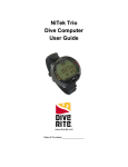
Unit Description
The UDI™ unit consists of the following:
3
2
4
5
1
7
6
1. Antenna
2. Up scroll button
3. Down scroll button
4.
5.
6.
7.
LCD display, plastic protector
Attachment buckle
Enter button
Emergency (SOS) button
The UDI™ contains the following functions:
Dive computer
Electronic compass
Message sending/receiving
Homing device
Emergency beacon
Dive logger
Use of these functions is explained below.
10
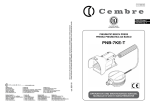
Using the quick connector
A quick connector is used connect the UDI™ unit to a power supply or to a PC.
Attach the quick connector to the UDI™ as show below, ensure the contacts are dry.
1
2
1. Quick Connector
2. Connector bracket on UDI
Charging the UDI
UDI™ uses a rechargeable internal Li battery. This battery can be recharged only with the UDI™ charger.
NOTE: Read Lithium Polymer Charging, Handling, Safety Information on page 3.
WARNING: The UDI™ is a completely sealed unit. It may stop functioning if opened. The warranty will
be void if the unit is disassembled or the seal is broken.
Ensure that the UDI™ is fully charged before your dive.
Charge the battery for 12 hours prior to the first time you use the UDI.
To charge the UDI:
Ensure that your hands, the UDI™ and the charger are dry!
Connect the quick adapter to the UDI
1. Connect the power charger to the quick connector.
2. Connect the power charger to a power supply. The green LED will turn on.
The charge is complete when the green light on the quick connector turns off.
11
NOTE: A steady or flashing red LED indicates a problem with the charger or the battery. Disconnect the
charger and repeat steps 2 to 4. If this does not resolve the problem, return the unit for service
Connecting the UDI™ to the PC
You can connect the UDI™ to the PC to perform data transfers, and dive simulations using the DiveSim
application. See page 48 for information on using DiveSim.
To connect the UDI™ to the PC:
1. Connect the quick connector to the UDI
2. Connect the USB cable to the quick connector.
3. Connect the USB cable to the computer.
NOTE: Ensure that you have properly installed the DiveSim software to be able to use this function.
To activate the connection to the PC, you must enable this option on the UDI. See page 20
12
Using the UDI
Turning UDI™ On and Off
To turn the UDI™ on:
1. Press and hold the Enter button for about 5 seconds. The UTC Proprietary screen opens.
(if pushing the Enter button for a short time, a message on the screen will appear mentioning the
need for a longer push)
NOTE: The UTC Proprietary screen contains a disclaimer. Clicking on the Enter button signifies that you
accept responsibility for use of the UDI, and that you accept the terms of the disclaimer.
If you do not agree, please do not dive with the UDI™.
2. Press the Enter button again. The current settings screen opens.
3. Press the Enter button again. The setup menu opens. After a few seconds, the dive computer
displays.
Standby
mode:
The UDI™ unit goes into Standby mode after 10 minutes of inactivity on the surface.
The UDI™ unit goes from Standby to Off after 1 hour of inactivity on the surface.
When in Standby mode, the UDI™ unit instantly returns to use upon contact with water, or
when a button is pushed for 2 seconds.
To turn UDI™ off:
Press and hold the Enter button for about 4-6 seconds. The UDI™ turns off.
WARNING:
Power cannot be turned off during a dive.
Scrolling the menus
To scroll through the menu options, press the Up or Down buttons.
To select an option, press the Enter button.
13
UDI™ main menu
The main UDI™ menu allows you to access UDI™ functions. The main menu flowchart is shown below.
Main
1. Messages
2. Navigation
3. Compass
4. Dive
Computer
5. Setup
Use of the various functions is described in detail as follows:
Setup – see page 15
Dive computer – see page 25
Messages – see page 30
Navigation – see page 32
Compass – see page 29
14
Setting up the UDI™
Use the Setup menu to set up the UDI™ for the following features:
RGBM Setup – Setup features of the RGBM model for use with the dive computer.
PC Connection – Connect to a PC for use with the DiveSim software.
List Sync. – Synchronize message and user lists with other UDI™ units.
Network Setup– Set network for communication with buddy.
UDI™ Setup – Set UDI™ parameters – clock, audio, light, units etc.
Main – Returns you to the Main menu.
The Setup menu flowchart is shown below.
1. RGBM
Setup
Setup
2. PC
Connection
3. List Sync.
4. Network
Setup
5. UDI Setup
6. Main
To enter the Setup menu:
1. From the Dive computer display, double-click Enter. The Main menu opens.
2. Use the Up/Down buttons to scroll to Setup.
3. Press Enter.
To exit the Setup menu and return to the Main menu, select Main, and press Enter.
15
RGBM Setup
Use the RGBM Setup options to set the features of the RGBM model for use with the dive computer.
The RGBM Setup flowchart is shown below.
RGBM
Setup
1. Water
Water (list)
2. Altitude
Altitude (list)
3. Nitrox
EAN 21-99
4. RGBM
Model
List 1 to 5
5. Deep Stops
Disable/ Enable
6. Dive Plan
Scroll up/down
7. New Diver
8. Setup
Entering/Exiting RGBM Setup mode
To enter RGBM Setup mode:
1. From the Main menu, select Setup and press Enter.
2. From the Setup menu, select RGBM Setup and press Enter.
To exit RGBM Setup mode:
Use the Up/Down buttons to scroll to SETUP, and press Enter this automatically saves all parameters
and configurations that you defined.
The saved parameters will be used as the default settings until such time that you modify them again.
16
Water
Select the water environment:
Salt or Fresh water and press
Enter
The default: Salt
WATER
09:35
25.3
1. Salt
2. Fresh
Altitude
The UTC RGBM model can be adjusted for high altitude dives where water bodies are above sea level.
Select the altitude group from four groups:
0 – 700 meters.
700 – 1500 meters.
1500 – 2400 meters.
2400 – 3700 meters.
Note: The display will be in meters or feet, depending on your UDI™ setup. See page 24.
Select altitude group that matches
your starting dive conditions and
press Enter.
The default: 0-700m
ALTITUDE
1. 0-700 m
2. 700-1500 m
3. 1500-2400 m
Nitrox
Set the gas mixture NITROX - can be set between EAN21 (air- 21% Oxygen) to EAN99 (99% Oxygen).
Use the Up/Down buttons to
change the EAN value from EAN 21
(air) to EAN 99 and press Enter.
NITROX
EAN 21 - Air
The default: Air (21%)
RGBM Model
Select the conservatism of the mathematical Nitrogen model. (See Appendix A – RGBM model for
information).
There are five conservative levels:
Model 4 - PPO2 < 1.40 ATM - Most conservative
Model 3 - PPO2 = 1.45 ATM
Model 2 - PPO2 = 1.50 ATM - Recommended
Model 1 - PPO2 = 1.55 ATM
Model 0 - PPO2 = 1.60 ATM - Least conservative
NOTE: UTC strongly advises the default use of Model 2 which gives full RGBM effect.
The dive model level considers several factors that may affect susceptibility of a diver to decompression
illness. These factors vary between divers, for the same diver from one day to the next; and are also
highly dependent on the health conditions of each diver.
17
UTC had not developed a decompression calculation model. We are licensed to use the RGBM model as
was defined and developed by Dr. Bruce Wienke. In no case UTC will be liable to any damage of
phenomena related to decompression thickness
The 5-step dive model allows you to set your personal adjustment mode. Some of the personal factors
that could affect susceptibility of a diver to decompression illness include:
Cold water – temperature less than 20oC (68 oF)
Physical fitness level
Fatigue
Hydration level
Stress
Obesity
Previous history of decompression illness
RGBM MODEL
Select the appropriate model and
1. Model 1
press Enter
2. Model 2
The default: Model 2
3. Model 3
Deep stops
Deep Stops are decompression stops that occur deeper than the traditional safety stop, with the purpose
of minimizing micro bubble formation and excitation.
You can choose the RGBM deep stop algorithm in addition to the traditional recommended safety stop.
Traditionally, for every dive deeper than 8 meters (26 feet), the diver should make a safety stop for 3
minutes between 3-6 meters (9-19 feet).
The RGBM model calculates deep stop iteratively, placing the first stop about halfway between the
maximum depth and the ceiling depth. After the first deep stop is completed, another deep stop will be
prompted halfway to the ceiling and so on when the last deep stop is placed at 5 meters (17 feet) for 2
minutes.
The duration of each deep stop is increased by one minute from one deep stop to another, with the first
deep stop duration being one minute.
When you enable Deep Stops, the traditional recommended safety stop is applied for a dive of less than
30 meters (98 feet). For dives deeper than 30 meters (98 feet), the Deep Stop algorithm is applied in
addition tothe traditionally safety stop.
NOTE: Deep Stops improve the diver safety. While ignoring these stops will not result in penalty during
repetitive dives we strongly recommend that the diver use these stops.
Select to Enable or Disable deep
stops and press Enter.
DEEP STOPS
1. Enable
2. Disable
The default: Enable
18
Dive Plan
The Dive Plan shows the calculated no-decompression time at the selected depth and the maximum
depth related to PPO2 toxicity, based on the RGBM settings selected, and current Nitrogen partial
pressure for the diver, taking into account the previous dives performed.
Use the Up/Down buttons to
change the depth in steps of 3
meters.
Press Enter to return to the RGBM
setup menu.
DIVE PLAN
Depth: 58
Time: 45
PO2 Depth: 19
New diver
Switch the UDI™ between divers by resetting the diving computer. This requires confirmation of the diver
to the disclaimer.
WARNING: The UDI™ must never be traded or shared between users while it is in operation. Switching
the UDI™ to a new diver using this feature will void any data from the previous diver.
Ensure that the new diver has not dived in the previous 24 hours prior to using the UDI™ – the
computer cannot account for dives performed without the UDI.
Ignoring this warning may result in serious injury or death!!!
1. The Disclaimer appears. Click
Enter.
2. Select Yes for a New Diver and
press Enter. The UDI™ is set
for a new diver
DISCLAIMER
By selecting YES, you certify that
the diver that intends to use this
device has not dived in the last 24
hours.
ENTER
NEW DIVER
Yes
No
19
PC Connection
Use the PC Connection option to connect UDI™ to your PC and use it with the DiveSim™ application. See
page 48 for information on using DiveSim™.
WARNING: Do not enter the water with the UDI™ when the “PC connection” is active. This will damage
your UDI.
NOTE: When the PC connection has not been used for 2 minutes, it becomes disabled to prevent any
damage to the UDI™ in case you forget to disable the PC connection option.
To use PC Connection:
1. Connect the quick connector to the UDI
2. Connect the USB cable to the quick connector.
3. Connect the USB cable to the PC computer.
4. On the UDI™ Setup menu, select PC Connection.
5. Select Enable press
PC Connection
Enter to enable the
1. Enable
PC Connection. A PC
2.
Disable
indication appears at
the bottom right
corner of the display
while the UDI™ is
connected to the PC.
NOTE: Communication with the UDI™ is done using the DiveSim™ software provided with your system.
See DiveSim™ software on page 48 for details.
20
List Sync
Use this option to synchronize the users list and messages list with other UDI™ users in the group.
1. Place the UDI™ units with the antennas touching or as close
as possible to each other.
2. In the Setup menu of each unit, select List Sync and press
Enter.
3. Select UDI™ Status and press
Enter. The UDI™ Status
menu opens.
4. Select whether your UDI™ will
be sending synch data or
receiving synch data and press
Enter.
Set the receiving UDI™
unit to Receiving.
Then set the sending unit
to Sending.
5. In the Direct List Sync. menu,
select Start Sync. to start the
synchronization process.
Always make sure the
receiving device is started the
first.
DIRECT LIST SYNC.
1. UDI Status
2. Start Sync.
3. Setup
UDI STATUS
1. Sending
2. Receiving
DIRECT LIST SYNC.
1. UDI Status
2. Start Sync.
3. Setup
6. Press Enter. The display shows Updating…
7. When the update is complete, the display reverts to the
Direct List Sync menu.
In case of a possible failure in the communication, the cycle
will repeat automatically – till the receiving UDI™ will
prompt “Copy succeeds”.
NOTE: If the synchronization fails, restart the process from Step 3.
21
Network Setup
Use this option to select User and Buddy numbers; and a network.
NOTE: You and your buddy must be properly defined on your UDI™ and your buddy’s UDI™ respectively,
and you must both be on the same network to be able to communicate using the UDI.
1. Select Net to define a network
to use, and press Enter.
NETWORK SETTING
4. Setup
1. Net
2. User
2. Select a network from 1 to 4,
and press Enter.
NETWORK
4. Net 4
1. Net 1
2. Net 2
3. Select User to define the user
name/number for the UDI™
and press Enter.
NETWORK SETTING
1. Net
2. User
3. Buddy
4. Select a User (named or
numbered) from the 14 users,
and press Enter.
USER
1. User 1
2. Brad
3. Jen
5. Select Buddy to define your
buddy number and press
Enter.
NETWORK SETTING
2. User
3. Buddy
4. Setup
6. Select a User (named or
numbered) from the 14
individual users, boat, or all
users and press Enter.
This will be your default for
sending a message to.
BUDDY
3. Jen
4. Bob
5. Armin
22
UDI™ Setup
Use the UDI™ Setup menu options to set the time, ring volume, light and units on your UDI.
Clock
Use this option to set the time and date.
1. Press Enter to select a time
unit.
2. Use the Up/Down buttons to
set the appropriate value.
3. Press Enter to move to the
next time unit on the list.
4. Repeat.
5. When you have set the year
value, press Enter to return to
the UDI™ Setup menu.
CLOCK SETUP
Minute:
Hour:
Date:
Month:
Year:
11
16
3
8
2007
Audio
Use this option to select an audio alert volume. Audio alerts sound to get your attention to the dive
computer under various events during a dive.
There are four levels of alert:
High
Med-High
Med
Low
AUDIO
Select a ring level and press Enter
1 High
2 Med-High
3 Med
Backlight
Use this option to select the time until the UDI™ backlight turns off. Shutoff interval of 5 seconds range
from 0 (off) to 55 seconds, and INF (infinite) when the backlight remains constantly lit.
NOTE: Extended use of the light may reduce battery time between charges.
Use the Up/Down buttons to
define a time value and press
Enter.
BACKLIGHT TIMER
Timer - 10 sec.
23
LED Control
Use this option to turn on or off the LED control which allows the LED on the UDI™ to blink when there is
an audible alarm or when a signal is received.
LED CONTROL
Select Enable or Disable and press
1. Enable
Enter.
2. Disable
The Default: Enable
LCD Contrast
Use this option to select a contrast level for the LCD display. .
The contrast interval ranges from 1 (very little contrast) to 7 (high contrast).
Use the Up/Down buttons to
define a contrast value and press
Enter. Make sure there are no
strips seen on the screen.
LCD CONTRAST
Contrast: 7
Units
Use this option to select Metric units (meters, degrees C) or Imperial units (Feet, degrees F) as your unit
of measurement.
UNITS
Select Imperial or Metric and press
1. Imperial
Enter. All units displayed on the
2. Metric
UDI™ will now conform to the unit
type chosen.
NOTE: The temperature displays according to your units selection – When you select Feet, Fahrenheit
degrees are shown, when you select Meters, centigrade degrees are shown.
About UDI
Use this option to view the UDI™ serial number and software version installed. Use this information when
contacting UTC about your UDI.
ABOUT UDI
31/05/2008
S/N: 20-111007
19:36
Version:
Ver_25.01.2008
Revert to factory settings:
In case you would like to revert to the original UDI™ factory settings, press the Up, Down and Enter
buttons simultaneously to start the UDI™ on. Wait for the UDI to turn on and for the message “set
default” appears on the screen. All customizations and settings you have done will be erased, and UDI
will turn on with the original factory settings.
24
Using the Dive Computer
The dive computer display contains a current and maximum depth indicator, a battery indicator, compass,
surface interval time (SIT), and fly time displays as well as additional parameters, depending on the dive
characteristics.
The dive computer display is the normal display mode that you use while diving.
From the
dive computer, you can:
Press the Up button to review your RGBM setup.
Press the Down button to review additional dive data.
Press the Enter button twice to go to the Main menu.
The dive computer display is different when the UDI™ is on the surface, and when the UDI™ is
underwater.
Surface display
On the surface, the dive computer display shows the following:
1
2
0.0
Depth
21 %
EAN:
PO2:
Depth
3
Net
: 2
Buddy:
User
1
SIT:-------
62
4
1. Current Depth and EAN indicator
2. Network & Buddy indicator
5
3. Battery indicator
4. Oxygen toxic limit depth
5. Surface interval time
Underwater display
Underwater, computer alternates between several displays, depending on your actual dive parameters:
Dive has not reached
decompression time.
Depth
:
Dmax:
15.4
32.0
124
Dive has not reached
decompression time – Press
the Enter button once to see
this display. The display stays
on for 7 seconds and then
returns to the original display.
Depth:
Dmax:
15.4
32.0
Safe depth:
22
Dive
Time:
Surf
Time:
25
15
4
No Deco:
Dive
Time:
Surf
Time:
25
15
Safe Time:
25
12
Dive has reached
decompression time.
Current Depth:33.4 Dive Time: 25
MAX Depth:
Ceiling:
Dive has reached
decompression time – Hold the
Enter button for 5 seconds to
see this display.
37.0
22
Time to surface: 15
Deco Time:
12
Current Depth:33.4 Dive Time: 25
MAX Depth:
Dsafe:
37.0
12
Time to surface: 15
Safe Time:
6
A or displays in the bottom left quadrant, accompanied by a tone to inform you to go up or down
when you overstep the bounds of decompression or safe diving time.
Dive computer parameters
Battery Indicator – Battery energy level.
Buddy – Name of buddy who will receive messages by default.
Ceil – Ceiling height for Decompression stop. The minimum depth allowed while in
decompression stop, in steps of 3 meters.
Deco time – Decompression time in minutes.
Depth - Current Depth indicator – Indicates current depth.
Dive time – Duration of current dive, in minutes.
Safe – Indicates Safety stop dept, between 3 - 6 meters.
Stop – Indicates Deep stop depth in a layer of 3 meters below the Deep stop.
EAN – Enriched Air Nitrox – indicates mixture percentage.
Fly Time – The minimum time required prior to flying (in Hours format HH:MM).
Heading – Heading direction in degrees from north.
Mdepth – Maximum depth achieved in current dive.
Net – Network used for communications.
No Deco – The remaining time before getting into decompression situation, at the depth
shown (in minutes).
PO2 Depth – Maximum depth allowed before Oxygen toxicity related to the PPO2 pressure
between 1.4 to 1.6 Atm.
Safe time – Safety stop time. Down counter from 3 minutes to zero.
SIT – Surface Interval Time - Counting the time the diver is out of the water to be calculated till
the next repetitive dive. When reaching to 24 hours, the dive computer will start a new dive
session (no Nitrogen residues).
Surf Time – The minimum expected time to the surface, taking in account all needed stops, in
minutes.
Reviewing RGBM setup and viewing additional data
While in Dive Computer mode, you can:
26
Press the Up button to see
your tissue saturation
graph.
When none of the tissues
are above 100% - you are
not in a deco situation
according to the UDI™
Press the Up button again
to review your RGBM setup
options.
100
%
1 2 3 4 5 6 7 8 9
RGBM SETUP
S/N:
99999999
Salt
Water
Altitude:
EAN
Press the Up button again
to review the second page
of the RGBM setup options.
Press the Up button one
more time or press the
Enter button at any time
to return to Dive computer
mode.
On the surface:
Press the Down button
see the compass.
Press the Down button
again to review dive
parameters.
Underwater:
Press the Down button
see the compass.
Press the Down button
again to review dive
parameters.
Press the Down button
again to review additional
dive parameters.
0-700m
21-Air
RGBM SETUP
Model: Model 2
O2 Max Depth: 61m
Deep Stop:
Disable
Last Dive Parameters
SIT: _________ Tdive: 26
Fly: _________ Dmax: 37
Dive No. 1
Temp: 23co
Dive Parameters
Total
Deco:
237
20:15
CNS:
051
Heading:
90o
OTU: 35.1
Dive Parameters
20:15
100%
Re-Dive factor:
Tem: 17oC
27
Abnormal conditions
Low battery prior to a dive
If the battery status becomes
empty prior to a dive, and the
15.4
depth
1
diver decides to dive despite this
dive time
32.0
max
warning, the UDI™ locks the dive
LOW BATTERY!!!
computer automatically for 24
Please
Charge UDI
hours starting at the end of the
dive and will ask the diver to
charge it.
UDI™ will continue to work as a timer and depth meter (gauge mode) only and will not calculate the
decompression parameters or other diving computer parameters.
WARNING: The UDI™ may turn itself off during the dive.
Low battery during dive
When the battery contains less than 3 hours charge, UDI™ will display a warning message and sound an
alert tone. Click Enter to return to the dive computer display.
When the battery contains less than 2 hours charge, UDI™ will display an additional warning message and
sound an alert tone. Click Enter to return to the dive computer display.
When the battery contains less than 1 hours charge, UDI™ will display yet another warning message and
sound an alert tone. Click Enter to return to the dive computer display.
Each transmission is shortening the battery tome of operation.
WARNING: In all cases of low battery alert, start ascent immediately, according to safe diving practice,
and recharge the UDI™ after you reach the surface.
Empty battery during dive
If the battery status becomes
empty during a dive, the battery
icon starts to flash in addition to
the UDI™ sounding an alert tone.
This indicates that the UDI™ can
continue to work for a half hour
with 1 transmission every 4
minutes.
depth
15.4
max
32.0
25
dive time
24
124
No deco
WARNING: Start ascent immediately, according to safe diving practice, and recharge the UDI™ after you
reach the surface.
28
Fast ascent
The maximum ascent rate is
limited to 10 meters (33 feet) per
minute.
In case of violation, the UDI™ will
sound an alert, and flash SLOW in
the display in the center of the
screen.
depth
25
15.4
dive time
max
32.0
SLOW!
ceil
5
3.0
Deco time
Use the ascent bar below the
battery indicator to guide your
ascent. Maximum ascent rate
allowed is reached when the bar is
full.
NOTE: A fast ascent can affect the calculations for subsequent dives. In these cases, subsequent dives
will be calculated using more conservative factors.
Safety stop and Deco stop violation
In case the diver over steps the
minimum ceiling depth of the deco
stop or the minimum depth of the
safety stop, the UDI™ sounds an
alert tone and displays an arrow
that points down.
depth
max
25
2.5
dive time
32.0
5
ceil
3.0
Deco time
depth
15.4
25
Severe decompression violation
If the diver violates the
decompression stop for at least
1 minute, or is out of bounds by at
least 2 meters (6.5 feet) from the
decompression depth, the UDI™
locks the dive computer and
continue only as a timer and
depth meter.
dive time
32.0
DECO VIOLATION
ERROR!
max
WARNING: In case of severe decompression violation, UDI™ will stay locked for the next 48 hours
after the end of the dive.
Using the Compass
The electronic compass display can be used to navigate and orient yourself underwater. This compass is
o
accurate within ±2 from the magnetic North.
The electronic compass accuracy is influenced by the presence nearby metal bodies and may be biased
dramatically.
See Care and maintenance on page 37 for information on periodic recalibration of the electronic compass.
29
To see the compass display:
From the Main menu, select Compass.
1
2
3
13:25
N
COMPASS CAL
25.5
63
MAIN
6
1. Magnetic North
2. Heading direction
3. Time
5
4
4. Depth
5 Back to Main menu
6 Your heading (Degrees)
To exit the compass display:
Select Main and click Enter.
Sending and receiving text messages
Messages are pre-set using the PC connection and UDI™ software. To modify the pre-set message list,
see page 55.
You can send messages to your buddy or other UDI™ users on the same network using the Send
Message function.
To enter the Message menu:
From the Main menu, select Messages and press Enter.
To exit the Messages menu and return to the Main menu, select Main, and press Enter.
Sending a message
The UDI™ unit can sent one of the 14 user-preset text messages to other UDI™ users.
To send a text message:
1. In the Messages menu, select
MESSAGES
New Message, then click
5. Main
Enter.
1. New Message
2. User to Send
2. In the Message list, choose a
message by scrolling with the
Up/Down buttons.
Click Enter.
MESSAGES
3. Boat above you !
30
3. In the Messages menu, User
to Send is selected.
Click Enter
MESSAGES
4. In the Send To menu, choose
a user by scrolling with the
Up/Down buttons.
Click Enter.
SEND TO
5. In the Messages menu, Send
is selected.
MESSAGES
1. New Message
2. User to Send
3. Send
6. Click Enter. The message is
sent. You are automatically
returned to the Main menu.
5. Main
1. New Message
2. User to Send
2. Bob
Viewing last message
1. In the Messages menu, select
Last Msg Rcv,
2. Click Enter. The last message
received is shown, and
identifies the sender and
network used.
3. Use the Up/Down buttons to
scroll the last five messages
received.
MESSAGES
3. Send
4. Last Msg Rcv
5. Main
Receiving a message
When you receive a text message from your buddy or another UDI™ user, your UDI™ unit sounds an
audible signal and blinking light (if enabled), and the message is automatically displayed.
The received message identifies
the message sender.
Only if the message is an SOS:
The depth of the diver sending the
message is also displayed in the
message.
In the example on the right, the
sender is Brad, at a depth of 8.3
meters.
MSG FROM
Brad
Boat above you !
Click Enter to turn off the audible
signal and automatically transmit
an acknowledgement signal to the
sender. After a short while, the
UDI™ return to the dive computer
display.
31
8.3
Navigation to a target
UDI™ can be used to track an SOS beacon or a Homing beacon.
A homing beacon transmits a homing signal from the boat unit on a specific dedicated frequency. An SOS
beacon transmits a homing signal on a specific frequency, received on all networks used with UDI.
Navigation using the UDI™ can be done only while the diver or beacon are moving in relation to each
other. In other words, the UDI™ diver, the beacon, or both must be moving, since the navigation beacon
relies on the Doppler Effect.
UDI™ can use one of two different navigation methods for tracking:
One step – corrects navigation as you dive showing the adjusted direction of the target beacon
on the UDI. Choose a random initial direction to start diving, then adjust as you go. This is the
UTC-recommended navigation method.
This is the recommended method to be used by most divers.
Two steps – recommended for use by experienced divers only. This method requires you to
dive 1 ½ times around a circle (1 to 2 meters (3 to 6 feet) in diameter) while using a point of
reference prior to showing you the direction of the target beacon on the UDI.
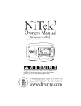
The differences in the two methods are illustrated below.
One-Step method (Recommended)
1
3
2
2
2
1. Starting location of diver
2. Course adjustments
3. Beacon location
Two-Steps method
1
2
3
1. Starting location of diver Circle a point of reference 1 ½ times to acquire vector
2. Course/Azimuth vector
3. Beacon location
32
To enter Navigation mode:
From the UDI™ Main menu, select Navigation and press Enter.
To exit the Setup menu and return to the Main menu, select Main, and press Enter.
Navigation mode and method
Navigation is used to dive to a homing beacon, or to a unit transmitting an SOS signal to provide
assistance.
You must select the tracking mode and the tracking method to use the UDI™ Navigation feature.
1. From the Navigation menu,
select SOS track to track an
SOS beacon, or Homing
track to track a Homing
beacon.
2. Press Enter.
3. Select One Step method or
Two Step method and press
Enter.
4. The Navigation display
opens.
(The example shown here is
for Two step navigation)
NAVIGATION
1. SOS track
2. Homing track
3. Mask Homing
NAVIGATION MODE
One Step method
Two Step method
13:25
N
-5
ACQUIS 10.5
Azim: 180
Start
Main
Using the Navigation display
In the One Step method, the display shows the track to your target. Keep an eye on the track to
navigate to your target. You should dive in a slight zig-zag direction to allow for more accurate navigation
towards your target.
In the Two Steps method, swim 1 ½ times around a fixed location to allow the UDI™ to acquire a
course. Once the course is acquired, keep an eye on the beacon relative direction to make sure that
you are not swimming away from your target.
33
The navigation display for one step navigation is explained below.
1
2
3
13:25
4
COMPASS CAL
TRACK 10.5
LOCK: 42
5
5
Start
Main
9
8
7
6
1. Beacon direction (relative to your
heading). Will appear in the first time
only if the Doppler value (see 9.) is
greater or equal 4).
2. Swim direction (your heading)
3. Time
4. Track – current track direction
5. Lock – the course you need to follow
to arrive at the beacon
6. Ascent bar – shows you the limits of your
ascent rate
7. Start – restart tracking. This is useful if
you suddenly loose the beacon
8. Doppler value bar – shows that you are
approaching (getting closer to) the target.
9. Doppler value - shows how quickly you are
approaching (positive numbers) or moving
away (negative numbers) from the target
The navigation display for two step navigation is explained below.
1
2
3
4
13:25
N
5
ACQUIS 10.5
Azim: 180
5
10
6
Start
Main
9
8
7
1. Beacon direction (relative to your
heading) – will appear ONLY after the
first step is successfully over, Will appear
in the first time only if the Doppler value
(see 9.) is greater or equal 4).
2. Swim direction (your heading)
3. North
4. Time
5. Acquis – current track step.
Will be changes to TRACK after the first
step is successfully finished
6. Azim – Azimuth/Course direction to
beacon (degrees from North)
7. Ascent bar – shows you the limits of your
ascent rate
8. Start – restart tracking. This is useful if
you suddenly loose the beacon.
9. Doppler value bar – shows that you are
approaching (getting closer to) the target.
10. Doppler value - shows how quickly you
are approaching (positive numbers) or moving
away (negative numbers) from the target
34
SOS Signals
Unlike other UDI™ signals, SOS signals are activated across all network channels, and have a longer range
than ordinary communications signals.
In the event of an emergency, you can activate your SOS signal by pressing the red H (Help) button on
your UDI™ for several seconds. An SOS signal is sent to all UDI™ users in the area.
EMERGENCY (HELP) BUTTON
Other UDI™ users can then home in and navigate to your location using the Navigation feature of their
units.
If you receive an SOS signal, your UDI™ unit sounds an audible signal, and the SOS message is
automatically displayed.
The SOS message identifies the
user sending the SOS, the network,
and the depth of the sender.
In the example on the right, the
sender is User 1, at a depth of 32
meters.
SOS DETECTED
User 1
Net :4
Depth: 32 m
Click Enter to turn off the audible
signal. UDI™ displays the
Navigation Mode screen.
Navigate to the diver in distress using one of the methods described on page 32.
Remote homing
UDI™ contains the ability to send a remote homing signal to the boat unit.
The remote homing signal takes the form of a message that cannot be modified or deleted from the
message list.
To activate the remote homing or remote SOS:
1. In the Message menu, select
Remote Homing from the list
MESSAGES
by scrolling with the
15. Remote Homing
Up/Down buttons, then click
Enter.
2. Click Send. The message is
sent
35
Remote SOS
UDI™ contains the ability to send a remote SOS signal to another user.
Failure to respond and cancel the request by the user receiving a remote SOS causes the UDI™ to start
sending SOS signal to the entire network. You will receive an SOS signal and navigate to the diver in
distress using one of the methods described on page 32.
The remote SOS signal takes the form of a message that cannot be modified or deleted from the message
list.
To activate the remote SOS:
1. In the Message menu, select
Remote SOS from the list by
scrolling with the Up/Down
buttons, then click Enter.
MESSAGES
14. Remote SOS
2. Click Send. The message is
sent
Mask Homing
You can temporarily mask the navigation homing beacon to prevent your UDI™ from sounding a homing
alarm when a homing signal is transmitted. This allows you temporarily disregard the homing signal until
the time you need it to return to the boat station.
NOTE: Masking the homing beacon does not mask any SOS beacons that may be activated during a dive.
To mask a homing beacon:
1. From the Navigation menu,
select Mask Homing and
press Enter.
NAVIGATION
1. SOS track
2. Homing track
3. Mask Homing
2. In the Mask Homing menu,
select Enable to mask the
beacon and press Enter.
MASK HOMING
1. Enable
2. Disable
When you enable Mask Homing, a small M is shown in the lower right corner of the LCD display.
36
Care and maintenance
UDI™ requires very little care or maintenance.
After every dive: wash and wipe down the UDI™ and make sure that the contacts are dry prior to
confectioning the UDI™ to the charger or the PC.
Do not use a water jet or pressure from hose to clean the UDI, to prevent damage to the UDI™
mechanism.
Periodically the UDI™ may need to be serviced at an authorized laboratory for calibration and battery
replacement. Consult the UDI™ webpage for information.
The UDI™ display protective sticker may get scratched and can be replaced. The UDI™ can be removed
from its housing for display housing replacement as shown in the diagram below.
Remove the cover by unscrewing the tops from the two hinge screws, and pulling the hinges out of the
housing. This frees the housing and allows you to remove it from the UDI™ unit.
You can then pop the protective cover out, and replace it with a new cover.
Revert to factory setting
In case you need to revert to the original UDI factory settings, press the Up, Down and Enter buttons
simultaneously (when the UDI™ is off). Wait for the UDI to turn on.
All customizations and settings you have done will be erased, and UDI will turn on with the original factory
settings.
37
Base [boat] unit
The boat unit is an optional component of the UDI™ system. It is used for text message communication
with the underwater divers, and its homing capabilities allow divers to navigate their way back to the boat.
The boat unit is shown below:
2
1
3
4
9
5
8
6
7
1. External connectors (for
siren and light)
2. LCD display, glass protector
3. Up and Down scroll buttons
4. Enter button
5. Alarm light
6. Antenna connector
7. Network selection buttons
and lights
8. Power charge connector
9. USB connector
38
The boat unit Antenna is shown below:
The UDI™ boat unit contains the following functions:
Electronic compass
Message sending/receiving
Homing beacon
Dive logger
Use of these functions is explained below.
Charging the UDI™ boat unit
UDI™ uses a rechargeable internal battery. You can use the boat unit running on a battery, or connected
to a power supply.
Connect the power adapter to the power connector on the UDI™ boat unit to recharge the battery or to
use the unit.
NOTE: Read Lithium Polymer Charging, Handling, Safety Information on page 3.
WARNING: The UDI™ boat unit is a completely sealed unit. It may stop functioning if opened. The
warranty will be void if the unit is disassembled or the seal is broken.
Connecting the UDI™ boat unit to the PC
You can connect the UDI™ boat unit to the PC to perform data transfers (messages table, users table),
using the DiveSim application. (See page 48 for information on using DiveSim).
To connect the UDI™ boat unit to the PC:
Connect the USB cable to the computer.
NOTE: Ensure that you have properly installed the DiveSim™ software to be able to use this function.
39
Turning UDI™ boat unit On and Off
To turn the UDI™ boat unit on:
1. Press and hold the Enter button for about 4 seconds. The UTC Proprietary screen opens, the
buzzer is heard and the LED is blinking.
2. Press the Enter button again. The current settings screen opens.
3. Press the Enter button again. The setup menu opens. After a few seconds, the dive computer
displays.
To turn UDI™ boat unit off:
Press and hold the Enter button for about 4 seconds. The UDI™ turns off.
Scrolling the menus
To scroll through the menu options, press the Up or Down buttons.
To select an option, press the Enter button.
UDI™ Boat unit main menu
The main UDI™ menu allows you to access UDI™ functions. The main menu flowchart is shown below.
Main
1. Messages
2. Compass
3. Trans.
Homing
4. Setup
The various functions are described in detail as follows:
Messages – see page 40
Compass – see page 42
Transmit homing – see page 43
Setup – see page 44
Sending and receiving text messages
Messages are pre-set using the PC connection and UDI™ software. To modify the pre-set message list,
see page 55.
You can send messages to UDI™ users on the same network using the Send Message function.
NOTE: Each network contains its own list of users and of preset text messages.
Messages and users can be updated using the PC connection for the active network only.
To enter the Message menu:
From the Main menu, select Messages and press Enter.
40
To exit the Messages menu and return to the Main menu, select Main, and press Enter.
Sending a message
The UDI™ unit can sent one of the 13 preset text messages to other UDI™ users.
To send a text message:
1. In the Messages menu, select
New Message, then click
Enter.
MESSAGES
5. Main
1. New Message
2. User to Send
2. In the Message list, choose a
message by scrolling with the
Up/Down buttons.
Click Enter.
MESSAGES
3. In the Messages menu, User
to Send is selected.
Click Enter
MESSAGES
4. In the Send To menu, choose
a user by scrolling with the
Up/Down buttons.
Click Enter.
SEND TO
5. In the Messages menu, Send
is selected.
MESSAGES
1. New Message
2. User to Send
3. Send
3. Boat above you !
5. Main
1. New Message
2. User to Send
2. Bob
6. Click Enter. The message is
sent. You are automatically
returned to the Main menu.
Viewing last message
1. In the Messages menu, select
Last Msg Rcv,
1. Click Enter. The last
message received is
shown, and identifies the
sender and network used.
2. Use the Up/Down buttons to
scroll the last five messages
received.
MESSAGES
3. Send
4. Last Msg Rcv
5. Main
41
Receiving a message
When you receive a text message from another UDI™ user, your UDI™ unit sounds an audible signal, and
the message is automatically displayed.
The received message identifies
the message sender and the
network on which it was sent.
MSG FROM
Brad
8.3
Coming back to boat
Only if the message an SOS:
The depth of the diver sending the
message is also displayed in the
message.
In the example on the right, the
sender is Brad, at a depth of 8.3
meters.
Click Enter to turn off the audible signal and return to the dive computer display.
Using the Compass
The UDI™ boat unit contains an electronic compass display. This compass is accurate within ±2 .
The electronic compass accuracy is influenced by the presence nearby metal bodies and may be biased
dramatically.
o
To open the compass display:
From the Main menu, select Compass.
1
2
3
13:25
N
COMPASS CAL
63
MAIN
4
1. Magnetic North
2. Swim direction
3. Time
4. Your heading (Degrees)
To exit the compass display:
Select Main and click Enter.
42
SOS Signals
Unlike other UDI™ signals, SOS signals are activated across all network channels, and have a longer range
than ordinary communications signals.
If you receive an SOS signal, your UDI™ boat unit sounds an audible signal, and the SOS message is
automatically displayed.
The SOS message identifies the
user sending the SOS, the network,
and the depth of the sender.
In the example on the right, the
sender is Brad, at a depth of 32
meters.
SOS DETECTED
Brad
Net :4
Depth: 32 m
Click Enter to turn off the audible signal.
Remote homing/Remote SOS
The boat unit contains the ability to send a remote SOS signal to a UDI™ user.
Failure to respond and cancel the request by the user receiving a remote SOS causes the receiving user
UDI™ to start sending SOS transmit the signal.
To activate the remote SOS:
In the Message menu, select
Remote SOS or Remote Homing
from the list by scrolling with the
Up/Down buttons, then click
Enter.
MESSAGES
14. Remote SOS
Click Send. The message is sent
43
Setting up the UDI Boat Unit
Use the Setup menu to set up the UDI Boat Unit for the following features:
PC Connection – Connect to a PC for use with the DiveSim software
List Sync. – Synchronize message lists with other UDI™ units (see DiveSim™ software page 48
for details)
UDI™ – Set UDI™ parameters – clock, audio, light.
The Setup menu flowchart is shown below.
Setup
1. List Sync.
2.Buddy
Select
3.UDISetup
To enter the Setup menu:
1. From the Main menu, use the Up/Down buttons to scroll to Setup.
2. Press Enter.
To exit the Setup menu and return to the Main menu, select Main, and press Enter.
44
List Sync
Use this option to synchronize the user list and message list with other UDI™ users. Messages and users
can be synchronized for the active network only.
If you want to update the list for the all 4 networks, you have to repeat this action, after selecting the
network before performing additional synchronization.
Note that the default Buddy selection is performed for the active network at the time of synchronization
1. Place the UDI™ units next to each other so that the
individual UDI™ unit antennas are touching the boat unit
antenna.
2. In the Setup menu of each unit, select List Sync and press
Enter.
3. Select UDI™ Status and press
Enter. The UDI™ Status
menu opens.
4. Select whether your UDI™ will
be sending synch data or
receiving synch data and press
Enter.
Set the receiving UDI™ unit(s)
to Receiving prior to setting
the sending unit to Sending.
DIRECT LIST SYNC.
1. UDI Status
2. Start Sync.
3. Setup
UDI STATUS
1. Sending
2. Receiving
5. In the Direct List Sync. menu, select Start Sync. to start
the synchronization process.
6. Press Enter. The display shows Updating…
7. When the update is complete, the display reverts to the
Direct List Sync menu.
If from some reason the process was not successful – it will
automatically repeat the process till the receiving unit is
showing Copy Succeed
UDI Boat unit setup
Use the UDI™ Setup menu options to set the time, ring volume, and backlight duration on the UDI™ boat
unit.
Clock
Use this option to set the time and date.
45
1. Select a time unit.
2. Use the Up/Down buttons to
set the appropriate value.
3. Press Enter to move to the
next time unit on the list.
4. Repeat.
5. When you have set the year
value, press Enter to return to
the UDI™ Setup menu.
CLOCK SETUP
Minute:
Hour:
Date:
Month:
Year:
11
16
3
8
2007
Audio
Use this option to select an audio alert volume. Audio alerts sound to get your attention.
There are four levels of alert:
High
Med-High
Med
Low
Select a ring volume and press
Enter
AUDIO
1 High
2 Med-High
3 Med
An external siren and flashing light can also be connected to the unit external connectors.
Backlight
Use this option to select the time until the unit backlight turns off. Shutoff interval ranges from 0 (off) to
55 seconds, in 5-second intervals, and INF (infinite) when the backlight remains constantly lit.
NOTE: Extended use of the light may reduce battery time between charges.
Use the Up/Down buttons to
define a time value and press
Enter.
BACKLIGHT TIMER
Timer - 10 sec.
LED Control
Use this option to define the Alarm LED light intensity. In day time – you may want higher intensity than
in the night. The default value is 50% intensity.
LCD Contrast
Use this option to select a contrast level for the LCD display. .
The contrast interval ranges from 1 (very little contrast) to 7 (high contrast).
46
Use the Up/Down buttons to
define a contrast value and press
Enter. Make sure there are no
strips seen on the screen.
LCD CONTRAST
Contrast: 7
Units
Use this option to select Metric units (meters, degrees C) or Imperial units (Feet, degrees F) as your unit
of measurement.
UNITS
Select Imperial or Metric and press
1. Imperial
Enter. All units displayed on the
2. Metric
UDI™ will now conform to the unit
type chosen.
NOTE: The temperature displays according to your units selection – When you select Feet, Fahrenheit
degrees are shown, when you select Meters, centigrade degrees are shown.
About UDI
Use this option to view the UDI™ serial number and software version installed. Use this information when
contacting UTC about your UDI Boat unit.
ABOUT UDI
31/05/2008
S/N: B20-111007
19:36
Version:
Ver_25.01.2008
Care and maintenance
The UDI™ boat unit requires very little care or maintenance.
After every dive: wash the antenna and antenna cable. Wipe down the UDI™ boat unit and make sure
that the connectors are well covered (using caps) and are dry prior to connecting the UDI™ to the charger
or the PC.
Do not use a water jet or pressure from hose to clean the UDI, to prevent damage to the UDI™
mechanism.
Periodically the UDI™ boat unit may need to be serviced at an authorized laboratory for calibration and
battery replacement. Consult the UDI™ webpage for information.
Revert to factory setting:
In case you would like to revert to the original UDI™ factory settings, press the Up, Down and Enter
buttons simultaneously. Wait for the UDI to turn on and for the message “set default” appears on the
screen. All customizations and settings you have done will be erased, and UDI will turn on with the
original factory settings.
47
DiveSim™ software
DiveSim is software designed to work with your UDI™ to perform the following actions:
Update your UDI™ message and user lists
Manage UDI™ log
Database management
Dive Simulator using the PC only
Dive Simulator using the UDI™ and DiveSim
Upgrading the UDI (or Boat unit) Firmware
Using the software
Download the most updated version from UTCs web site at : www.utc-digital.com under Support ,
Download.
Save the Zip file on your desktop.
Un-zip the file and extract it to you Desktop (one single set file will be created).
Start the installation file, making sure the UDI is NOT connected to the PC, or the Quick Connect device.
At the end of the installation process, a DiveSim shortcut appears on your desktop.
Also – under the group “Underwater Technologies Center” (under programs), you will find the Instructions
manual etc.
Open DiveSim by double-clicking on the DiveSim shortcut.
DiveSim opens in the PC Simulator window:
1
2
3
4
5
8
6
7
1. Menu selection
2. About DiveSim
5. Tissue saturation graph
6. Diving configuration panel
48
3. UDI™ connection status
4. Metric/Imperial unit toggle
7. Dive computer display panel
8. Dive depth graph
When connecting the UDI to the PC (using the Quick Connector and the USB cable, making sure the UDI
is the to “PC Connection” enable, there is an automatic check for possible Firmware (internal UDI
software) newer version. If the is such version – you well be offered to upgrade.
UTC is strongly recommends to always use the most updated version.
In order to make such upgrade possible, you have to download the most recent available software from
UTC web site (www.utc-digital.com), at the specific location: http://www.utcdigital.com/downloads.asp?cid=106&pr=39 .
After downloading the file from the web site, save it on your desktop. Un-zip the file (to you desktop).
Run the unzipped file and the most updated DiveSim software as well as the most updated UDI software
will be available to you.
You can always initiate the upgrading process by going into the “about DiveSim” button on the upper right
corner of the screen.
The menu selection bar contains the following options:
Update your UDI™ – manage and update your UDI™ user lists and list of messages (see page
54)
Manage UDI™ log - manage and save dives log data from your UDI™ to the PC (see page 53)
Database - load and maintain dive-data information on the PC (see page 52)
PC Simulator - perform a dive simulation without connecting the UDI™ to the computer (see
page 50)
49
UDI™ Simulator - perform a dive simulation by connecting the UDI™ to the computer (see page
51).
Use and functions for each of these options is described below.
PC Simulator
The PC Simulator function is used to perform a dive simulation without connecting the UDI™ to the
computer.
The PC Simulator Dive depth graph shows the dive profile over time. In a dive simulation, the divedepth profile updates twenty times faster than real-time.
The Tissue saturation graph updates as a function of the dive depth profile and is calculated at the
speed of the dive simulation.
The Dive configuration panel is used to adjust the dive parameters on the simulator as they are also
defined in the RGBM dive computer.
It contains the following:
Conservatism level – select from one of the 5 available levels (see RGBM Model on page 17)
Altitude – select an altitude level for your dive location (see Altitude on page 17)
EAN – define Nitrox percentage (see Nitrox on page 17)
Max depth – insert maximum depth as if you are using in a dive plan, to determine the PO2
limit.
Salt water – check if this is a salt water dive simulation
Deep stops enabled – check to allow this option.
The Dive computer display panel contains dive the computer data shown in the UDI™ dive computer
display (see Using the Dive Computer on page 25).
50
The top of the Dive computer display contains the Up and Down buttons that serve a similar function to
the Up and Down buttons on the UDI™ unit.
Click the Up button to see the RGBM setup parameters.
Click the Down button to see the last diver parameters.
The left side of the Dive computer display contains the simulator controls which are used to simulate a
dive:
Up arrow – moves the diver up
Down arrow – moves the diver down
Forward arrow – maintains the diver at the selected depth
Pause button – pauses the simulation. When paused, the button is red.
UDI™ Simulator
The UDI™ Simulator function is used to perform a dive simulation by connecting the UDI™ to the
computer, and seeing the way a dive plays out on the UDI.
During a simulated dive using this function, the UDI™ reacts exactly in the same way as it would in a real
dive. This allows you to test your planned dive.
The UDI™ Simulator Dive depth graph shows the dive profile over time. In a dive simulation, the divedepth profile updates twenty times faster than real-time.
The Tissue saturation graph updates as a result of the dive depth profile and is calculated at the speed
of the dive simulation. This is actually the calculation performed by a dive computer.
The Dive configuration panel displays the dive parameters on the simulator.
It contains the following:
Conservatism level – shows one of the 5 available levels
Altitude – shows the altitude level for your dive location.
EAN – shows Nitrox percentage defined
Max depth – shows the maximum depth, to determine the PO2 limit.
Salt water – checked if this is a salt water dive simulation
Deep stops enabled – checked to allow this option.
The Dive computer display panel contains dive the computer data shown in the UDI™ dive computer
display (see Using the Dive Computer on page 25).
51
The top of the Dive computer display contains the Up and Down buttons that serve a similar function to
the Up and Down buttons on the UDI™ unit.
Click the Up button to see the RGBM setup parameters.
Click the Down button to see the last diver parameters.
The left side of the Dive computer display contains the simulator controls which are used to simulate a
dive:
Up arrow – moves the diver up
Down arrow – moves the diver down
Forward arrow – maintains the diver at the selected depth
Pause button – pauses the simulation. When paused, the button is red.
Database function
The Database function is used to load and maintain dive data information on the PC.
The database function contains 3 tabs:
PC Simulator log
UDI™ Simulator log
UDI™ Logbook on PC
Each of these tabs contains a table with a list of Files/Devices and Time, Data and Index data.
Data can be loaded to the database using the Load Dive button.
A database entry can be deleted by selecting it and clicking the x delete button
52
Manage UDI™ log
The Manage UDI™ log function allows you to manage and save dive log data from your UDI™ to the PC.
To manage your UDI™ log.
1. Connect the UDI™ to the PC USB port.
2. On the UDI, select Setup > PC Connection > Enable.
The Manage UDI™ log window shows a list of UDI™ logged dives.
Select the wanted dives, and click Get from UDI™ to save them to the PC.
Select the wanted dives, and click Erase to erase them to the UDI.
Erase
53
Update your UDI
The Update your UDI™ function is used to manage and update your UDI™ user lists and list of
messages.
To modify you list of UDI™ users
1. Click Update your UDI, and click the Your UDI™ Users tab.
2.
You can:
Click New group to create a new group of users
Select an existing group, and click Edit to edit the user list.
Select an existing group and click Delete to remove the group.
When you create or edit a group of users, the Edit Users list appears.
Place your cursor in the entry box, and type the name of a new user.
Click Clear to delete the name of a user.
Click Save when you have finished editing the list. The list appears on the right side of the Your
UDI™ Users tab and is saved on your PC.
54
NOTE: The update is done on both user and messages tables simultaneously. Therefore, you should
finish editing both tables prior to performing the update.
To send a list of users to your UDI:
2. In the UDI™ menu, select Setup > PC Connection > Enable.
3. Verify that the UDI™ is connected to the PC by looking at the UDI™ connection status sign on the
UDI™ display.
4. Click Send to UDI. The list gets sent to the UDI.
5. When the process in completed, the following message appears:
6. Click OK to return to the Update your UDI™ window.
To modify you list of UDI™ Messages:
1. Click Update your UDI, and click the Your UDI™ Messages tab.
2.
You can:
Click New group to create a new group of users
Select an existing group, and click Edit to edit the user list.
Select an existing group and click Delete to remove the group.
When you create or edit a group of messages, the Edit Messages list appears.
Place your cursor in the entry box, and type a new message.
55
Click Clear to delete a message.
Click Save when you have finished editing the list. The list appears on the right side of the Your
UDI™ Messages tab.
To send a list of messages to your UDI.
1. In the UDI™ menu, select Setup > PC Connection > Enable.
2. Verify that the UDI™ is connected to the PC by looking at the UDI™ connection status sign on the
UDI™ display.
3. Click Send to UDI. The list gets sent to the UDI.
4. When the process in completed, the following message appears:
5. Click OK to return to the Update your UDI™ window.
56
Appendix – RGBM Model
The Reduced Gradient Bubble Model is an algorithm developed by Dr. Bruce R. Wienke that is used
to calculate the decompression stops needed for a particular dive profile. It assumes asymmetric off
gassing and compensates for nitrogen microbubbles, which can reduce the rate of off gassing.
The RGBM has gained tremendous popularity in the recreational and technical diving worlds in just the
past few years.
The RGBM algorithm considers various factors, including the maximum depth reached during the dive and
the length of time underwater. For repetitive dives it also includes the surface interval, or the time spent
above the water between the previous dive and the start of the current dive. This information is used to
calculate the amount of residual nitrogen build-up in the diver's tissues after completing a dive.
The RGBM:
Monitors continuous multiday diving
Computes for closely spaced multiple dives
Computes for a dive that is deeper than the previous one
Adapts for rapid ascents which build up microbubbles
The algorithm provides additional safety features though its ability to be set for a variety of situations and
dive profiles.
Depending on the situation, the RGBM adapts decompression data by:
Reducing no-decompression stop dive times,
Adding mandatory safety stops
Increasing decompression stop times
Increasing the surface interval
The UDI™ allows the diver to choose between the traditional recommended safety stop and deep stops.
Deep stops occur deeper than traditional stops to minimize microbubble formation.
The RGBM model calculates deep stops iteratively, placing the first stop at approximately halfway between
the maximum depth and the ceiling depth. After completing the first deep stops, another deep stop is set
halfway to the ceiling and so on.
Personal adjustment
Divers can input personal adjustments into the RGBM decompression model. There are 5 modes to choose
from. Factors which can affect which mode to choose vary between divers, and for the same diver from
one day to the next. The factors which can increase susceptibility to decompression illness include, but are
not limited to:
Cold exposure
Fitness level
Fatigue
Dehydration
Previous cases of decompression illness
Stress
Obesity
The model should be adjusted to a conservative level, according to personal experience and ability. Under
ideal conditions, use the default value of mode 2.
If conditions are more difficult, choose a more conservative model. The UDI™ adjusts the RGBM model
according to the mode entered, and provides appropriate decompression times.
57
The UDI™ also allows more experienced divers who are willing to accept some risks to choose a lesser
level of conservativeness.
Additional, in-depth information about the RGBM can be found in:
http://www.rgbmdiving.com/index.htm
REDUCED GRADIENT BUBBLE MODEL
WITH BASIS AND COMPARISONS
NAUI Technical Series 8
Bruce R. Wienke and Timothy R. O’Leary
http://www.scuba-doc.com/rgbm.pdf
REDUCED GRADIENT BUBBLE MODEL:
DIVING ALGORITHM, BASIS, AND COMPARISONS
Bruce R. Wienke and Timothy R. O’Leary
http://www.scuba-doc.com/rgbmim.pdf
58