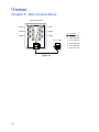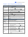
1
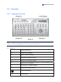
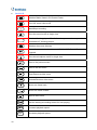
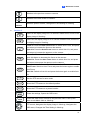
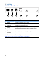
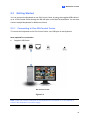
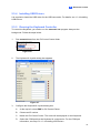
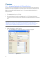
GV-Keyboard V3
User's Manual
Before attempting to connect or operate this product,
please read these instructions carefully and save this manual for future use.
© 2010 GeoVision, Inc. All rights reserved.
Under the copyright laws, this manual may not be copied, in whole or in part,
without the written consent of GeoVision.
Every effort has been made to ensure that the information in this manual is
accurate. GeoVision, Inc. makes no expressed or implied warranty of any kind
and assumes no responsibility for errors or omissions. No liability is assumed
for incidental or consequential damages arising from the use of the information
or products contained herein. Features and specifications are subject to
change without notice.
GeoVision, Inc.
9F, No. 246, Sec. 1, Neihu Rd.,
Neihu District, Taipei, Taiwan
Tel: +886-2-8797-8377
Fax: +886-2-8797-8335
http://www.geovision.com.tw
Trademarks used in this manual: GeoVision, the GeoVision logo and GV
series products are trademarks of GeoVision, Inc. Windows and Windows XP
are registered trademarks of Microsoft Corporation.
July 2011
Contents
Regulatory Notices.................................................................................1
Naming and Definition ...........................................................................2
Introduction ............................................................................................3
Chapter 1
1.1
1.2
1.3
1.4
1.5
1.6
Introduction...............................................................................................................4
1.1.1
Packing List ....................................................................................................4
1.1.2
System Requirements....................................................................................5
Overview...................................................................................................................6
1.2.1
Keyboard Overview ........................................................................................6
1.2.2
Rear Panel Overview .....................................................................................9
Getting Started........................................................................................................10
1.3.1
Connecting to One GV-System ....................................................................10
1.3.2
Connecting to Multiple GV-Systems............................................................. 11
1.3.3
Connecting Multiple Keyboards for Different Monitors .................................13
1.3.4
Installing USB Drivers ..................................................................................14
1.3.5
Running the Keyboard Controller .................................................................15
1.3.6
Using the Keyboard for Login.......................................................................17
Advanced Settings..................................................................................................18
1.4.1
Setting Function Keys ..................................................................................18
1.4.2
Setting a Keyboard for Multiple GV-Systems ...............................................20
1.4.3
Assigning Keyboards for Different Monitors .................................................21
On-Screen Display Menus......................................................................................23
1.5.1
The OSD Menu in GV-System .....................................................................23
1.5.2
The OSD Menu in ViewLog ..........................................................................25
Shortcut Key Conflict Test ......................................................................................26
Chapter 2
2.1
2.2
2.3
GV-System ..........................................................................4
GV-Control Center ............................................................27
Introduction ...........................................................................................................27
2.1.1
Packing List ..................................................................................................27
2.1.2
System Requirement....................................................................................28
Overview.................................................................................................................29
2.2.1
Keyboard Overview ......................................................................................29
2.2.2
Rear Panel Overview ...................................................................................32
Getting Started........................................................................................................33
2.3.1
Connecting to One GV-Control Center.........................................................33
2.4
2.5
2.3.2
Connecting to Multiple GV-Control Centers .................................................34
2.3.3
Connecting Multiple Keyboards for Different Monitors .................................36
2.3.4
Installing USB Drivers ..................................................................................37
2.3.5
Running the Keyboard Controller .................................................................37
Advanced Settings..................................................................................................39
2.4.1
Setting Function Keys ..................................................................................39
2.4.2
Setting a Keyboard for Multiple GV-Control Centers....................................41
2.4.3
Assigning Keyboards for Different Monitors .................................................42
On-Screen Display Menus......................................................................................44
2.5.1
The OSD Menu in Matrix View .....................................................................44
2.5.2
The OSD Menu in ViewLog ..........................................................................45
Chapter 3
Direct Connection to PTZ Cameras ................................46
3.1
Installing PTZ Cameras ..........................................................................................47
3.2
Setting up PTZ Cameras ........................................................................................48
Chapter 4
Upgrading the Firmware ..................................................49
Chapter 5
Wall Terminal Block .........................................................50
Chapter 6
Basic Programming and Operation ................................51
Troubleshooting ...................................................................................52
Specifications .......................................................................................53
Appendix ...............................................................................................54
Regulatory Notices
Regulatory Notices
FCC Notice
This equipment has been tested and found to comply with the limits for a Class A digital
device, pursuant to part 15 of the FCC Rules. These limits are designed to provide reasonable
protection against harmful interference when the equipment is operated in a commercial
environment.
Class A
This equipment generates, uses, and can radiate radio frequency energy and, if not installed
and used in accordance with the instruction manual, may cause harmful interference to radio
communications. Operation of this equipment in a residential area is likely to cause harmful
interference in which case the user will be required to correct the interference at their own
expense.
CE Notice
This is a Class A product. In a domestic environment, this product may cause radio
interference in which case the user may be required to take adequate measures.
RoHS Compliance
The Restriction of Hazardous Substances (RoHS) Directive is to forbid the use of hazardous
materials of production. To meet the RoHS Directive requirements, this product is made to be
RoHS compliant.
WEEE Compliance
This product is subject to the Waste Electrical and Electronic Equipment (WEEE) Directive
and made compliant with the WEEE requirements.
1
Naming and Definition
GeoVision Analog and Digital Video Recording Software. The GVGV-System
System also refers to GV-Multicam System, GV-NVR System,
GV-DVR System and GV-Hybrid DVR System at the same time.
2
Introduction
Introduction
The GV-Keyboard V3 is designed to program and operate GV-System / GV-Control Center,
and it can also be connected with PTZ cameras directly for PTZ control.
Key Features:
•
A Keyboard can control up to 16 GV-Systems / 16 GV-Control Centers.
•
Multiple Keyboards can work with up to 8 monitors for Digital Matrix, TV Quad and Spot
Monitor applications in GV-System.
•
Multiple Keyboards can work with up to 8 monitors for Matrix View and ViewLog
applications in GV-Control Center.
•
A Keyboard can directly set up and control up to 32 PTZ cameras.
GV-System:
If you use the Keyboard with GV-System, see Chapter 1 for detailed installation and
operations.
GV-Control Center:
If you use the Keyboard with GV-Control Center, see Chapter 2 for detailed installation and
operations.
PTZ Cameras:
If you use the Keyboard to directly control PTZ cameras, see Chapter 3 for detailed
installation and operations.
Important:
1.
The Keyboard for GV-System and for GV-Control Center has a different button
design.
2.
The Keyboard is protected with a password. Every time when you use the Keyboard,
you will need to enter the default password ”0000” to unlock it. To change the default
password and set the auto lock time, see Chapter 6 Basic Programming and Operation.
3.
To see the list of PTZ camera protocol supported by the Keyboard for direct control,
see Supported PTZ Protocols and Brands, Appendix.
3
Chapter 1
GV-System
This chapter is for users that connect the Keyboard to the GV-System.
1.1 Introduction
You can use the Keyboard to program and operate GV-Systems. You can also connect
multiple Keyboards to control assigned monitors for Digital Matrix, TV Quad and/or Spot
Monitor applications.
Key Features
•
Up to 16 GV-Systems supported
•
Up to 8 monitors for Digital Matrix, TV Quad and Spot Monitor applications can work with
multiple Keyboards
•
OSD panel supported
Note: The Keyboard also supports controlling any PTZ camera connected to GV-System.
Click Here to see the supported IP cameras. You can also find the supported PTZ cameras
from Supported PTZ Protocol and Model, Appendix, DVR User’s Manual on the Surveillance
System Software DVD.
1.1.1
Packing List
•
GV-Keyboard x 1
•
Power Adaptor (DC Output 12V, 1A) x 1
•
USB Cable x 1
•
RJ-11 Cable x 1
•
Wall Terminal Block x 1
•
GV-Keyboard Software CD x 1
•
GV-Keyboard Quick Start Guide x 1
4
1
GV-System
1.1.2 System Requirements
OS Supported
System Supported
32-bit
Windows XP / Vista / 7 / Server 2008
64-bit
Windows 7 / Windows Server 2008
GV-System V8.4 or later
Note: Currently, GV-Keyboard V3 does not support embedded operating systems.
5
1.2 Overview
1.2.1
Keyboard Overview
Figure 1-1
Note: The difference between the Keyboard for GV-System and for GV-Control Center is at
the section B buttons, highlighted in the red square in above figure.
z
Section A
☼
Yellow POWER LED.
RX
Red RX LED (Receive).
TX
Green TX LED (Transmit).
P1
Changes DVR ID.
P2
Select a PTZ camera to control.
P3
Configures the Keyboard parameters, including password, key
beep and auto-lock period.
P4
Sets up the PTZ camera settings.
P5
Displays the firmware version.
Locks the Keyboard.
F1-8
6
Function keys.
1
z
GV-System
Section B
Launches Multicam Surveillance System (GV-System).
Turns full screen view on/off.
Turns the sound on/off.
Starts/Stops recording.
Launches ViewLog.
Switches the screen divisions.
Plays next events automatically.
Starts/Stops the scheduled recording.
Goes to the previous event.
Goes to the next event.
Plays/Pauses a video event.
Rewinds/Pauses a video event.
Moves one frame back.
Moves one frame forward.
Stops a video event.
Sets the starting and ending frames for auto playing.
Increases playback speed.
Decreases playback speed.
7
Switches to the previous screen or camera.
Switches to the next screen or camera.
z
Numeric
Enters the login password; Selects a specific camera; Changes the
buttons
Time Setting in ViewLog.
Section C
Zooms in the display image of PTZ camera in GV-System; Zooms in
the display image in ViewLog.
Zooms out the display image of PTZ camera in GV-System; Zooms
out the display image in ViewLog.
Focus In: Press the Auto Focus button to select Auto Focus, and
press this button to increase the focus on the camera.
Open Iris: Press the Auto Focus button to select Auto Iris, and press
this button to increase the aperture on the camera.
Focus Out: Press the Auto Focus button to select Auto Focus, and
press this button to decrease the focus on the camera.
Close Iris: Press the Auto Focus button to select Auto Iris, and press
this button to decrease the aperture on the camera.
Press the button for 2 sec. to switch between Auto Focus and Auto
Iris.
Auto Focus: Switch to Auto Focus and press the button again to
enable Auto Focus.
Auto Iris: Switch to Auto Iris and press the button again to enable
Auto Iris.
Sets the PTZ camera for auto mode.
Moves the PTZ camera to the default position.
Moves the PTZ camera to a preset location.
Calls up the Login dialog box; Enters the settings; Opens the OSD
menu.
Closes the OSD menu; Returns to the previous menu; Calls up the
menu to exit GV-System or ViewLog.
PTZ control; Navigates the display image in ViewLog; Navigates the
OSD menu; Changes the Time Setting in ViewLog.
8
1
1.2.2
GV-System
Rear Panel Overview
Figure 1-2
No Name
Function
1
Joystick
Connects to GV-Joystick for PTZ control.
2
DC 12V
Connects to the power adaptor.
3
USB1 Port
Connects to one GV-System.
4
5
6
RS-485
Port (RJ-11)
Terminal
Resistance
Reset
Through the supplied Wall Terminal Block, the RS-485 port can
connect to up to 16 GV-Systems. For details see 1.3.2
Connecting to Multiple GV-Systems.
Used in the last daisy-chained GV-System.
Resets the Keyboard when it does not respond to commands.
Note: There is no such function of loading default in the Rest button.
9
1.3 Getting Started
You can connect the Keyboard to one GV-System by using the supplied USB cable, or up to
16 GV-Systems through the RS-485 pins on the Wall Terminal Block. You can also connect
multiple Keyboards for different monitors.
1.3.1
Connecting to One GV-System
To connect the Keyboard to one GV-System, use USB port on the Keyboard.
Item required for connection:
z
Supplied USB Cable
GV-System
Figure 1-3
Note: When you use the USB port on the Keyboard for connection, it is not required to
connect the Keyboard to a power supply.
10
1
1.3.2
GV-System
Connecting to Multiple GV-Systems
You can connect one Keyboard to up to 16 GV-Systems and switch control among them. To
connect multiple GV-Systems, use the RS-485 port on the Keyboard. See the diagram below
for connection.
Items required for connections:
z
Supplied RJ-11 Cable
z
Supplied Wall Terminal Block
z
Supplied Power Adaptor
z
RS-485/RS-232 interface converter, e.g. GV-NET Card, GV-NET/IO Card, GV-Hub V2
and GV-COM V2
Use the RJ-11 cable to connect between the RS-485 port on the Keyboard and the Wall
Terminal Block. Then connect the Pin-2 (Black wire) and Pin-6 (White wire) of the Wall
Terminal Block to the RS-485/ S-232 interface converter, which then connects to the
GV-System.
11
The diagram below illustrates the wiring to multiple GV-Systems and uses GV-NET Card as
RS-485/RS232 interface converter as example.
Figure 1-4
Note:
1.
Because RS-485 communication has distance limitation, the distance between each
Keyboard and the GV-System must be within 600 meters (1968.5 feet).
2.
You can only use either USB port or RS-485 port on the Keyboard. Don’t connect the
USB cable on the Keyboard when using RS-485 connection.
To set up the Keyboard to control multiple GV-Systems and switch control among these
servers, see 1.4.2 Setting a Keyboard for Multiple GV-Systems.
12
1
1.3.3
GV-System
Connecting Multiple Keyboards for Different Monitors
To use multiple Keyboards to control assigned monitors, use RS-485 cables to connect
additional Keyboards to RS-485/RS-232 interface converters, and then connect these
RS-485/RS-232 interface converters to the GV-System through USB ports.
A total of 8 Keyboards can be connected to control 8 assigned monitors for Digital Matrix, Spot
Monitor and/or TV Quad applications in the GV-System.
Items required for connection:
z
Supplied USB Cable
z
RS-485/RS-232 interface converter, e.g. GV-Hub V2 and GV-COM V2
Figure 1-5
To assign a Keyboard for a spcific monitor control, see 1.4.3 Assigning Keyboards for
Different Monitors.
Note:
1.
For Digital Matrix function, the maximum of 8 monitors can be applied; for Spot
Monitor function, the maximum of 2 monitors can be applied; for TV Quad function, the
maximum of 5 monitors can be applied. But, a total of 8 monitors (no matter from which
functions) can work in conjunction with 8 assigned Keyboards.
2.
Because RS-485 communication has distance limitation, the distance between each
Keyboard and the GV-System must be within 600 meters (1968.5 feet).
13
1.3.4
Installing USB Drivers
It is required to install the USB driver for the USB connection. When the Windows Found New
Hardware Wizard pops up, ignore the Wizard and follow the steps below to install the driver:
Note: You can only install the drivers by using the attached Software CD, or the Software
DVD of GV-System V8.5 or later.
1.
Insert the Software CD. This window pops up.
Figure 1-6
2.
Select Install Geovision USB Devices Driver. This dialog box appears.
Figure 1-7
3.
Click Install to install the driver. When the installation is complete, this message will
appear: Install done!
4.
Click Exit to close the dialog box.
5.
To verify that the driver is installed correctly, go to Windows Device Manager. In the
Ports (COM & LPT) field, you should see the entry for STM Virtual COM Port.
Figure 1-8
Note: Remember the COM port showing in the STM Virtual COM Port entry. It indicates
the port number that the Keyboard is using.
14
1
1.3.5
GV-System
Running the Keyboard Controller
To control the Keyboard, you need to run the mcamctrl.exe program always at the
background.
1.
Run mcamctrl.exe from the GV folder.
Figure 1-9
2.
The Keyboard & Joystick dialog box appears.
Figure 1-10
3.
Configure the Keyboard & Joystick dialog box.
A.
At the top left, select DVR for GV-System.
B.
Choose an ID number.
C.
Name the GV-System. The name will be displayed on the Keyboard.
D.
Select the COM port that the Keyboard is connected to. For the COM port
information, see step 5 in 1.3.4 Installing USB Drivers.
4.
Click ► to start the service. The Keyboard is now enabled to control GV-System.
15
The fields on the Keyboard & Joystick Controller dialog box:
Name
Description
Select the Keyboard to define F1-F8 functions.
Select DVR for the connected GV-System.
ID
Select an ID number for the GV-System. The default is 1.
Name
Give the GV-System a descriptive name.
Startup type
PTZ Speed
Monopoly Mode
Select Manual or Automatic to choose whether to run the controller
at next startup or not.
Adjust PTZ speed.
Assign the Keyboard to control a specific monitor and set up the
control mode.
Select the COM port connecting to the Keyboard. Find the COM port
Device 1-8
number the Keyboard is using in the Ports field of Windows Device
Manager.
►
Start the service.
■
Stop the service.
F1 - F8
Define eight function keys on the Keyboard to control output
modules, display layout, PTZs, cameras and etc.
Print out a label for the eight function keys.
Note:
1.
To use the Keyboard to control multiple GV-Systems, see 1.4.2 Setting a Keyboard
for Multiple GV-Systems for further setup and operation.
2.
To use more than one Keyboard to control assigned monitors, see 1.4.3 Assigning
Keyboards for Different Monitors for further setup.
3.
To use function keys (F1-F8) on the Keyboard for instant access to many functions,
see 1.4.1 Setting Function Keys.
16
1
1.3.6
GV-System
Using the Keyboard for Login
You can use the Keyboard to log into the GV-System instead of using the general keyboard
and mouse. For this kind of login, you must export the login ID and password from the
GV-System first.
Note: The login IDs and passwords you set up can only be composed of digits.
1.
Click the Configure button, select System Configure, select Password Setup and
select Local Account Edit. The Password Setup dialog box appears.
Figure 1-11
2.
Select a user from the user list, and select Export this ID for IR Remote Control
(GV-Keyboard) to export the ID and Password to the Login dialog box. Click OK.
After you complete the above setting, you can start to use the Keyboard to log into the
GV-System. Click
to log into the GV-System. You will see the exported ID in the ID
drop-down list of the Login dialog box. Click
and click
to select the user’s ID. Type the password
.
17
1.4 Advanced Settings
Advanced Settings allows you to set up hot keys for instant access to many functions, set up a
Keyboard for multiple GV-Systems or assign Keyboards for different monitors.
1.4.1
Setting Function Keys
To set up hot keys for instant access to many functions, follow the steps below.
1.
Click a function key (F1-F8) to be configured. If multiple Keyboards are connected, first
select one from
drop-down list. This dialog box appears.
Figure 1-12
2.
Select a desired function.
3.
Click OK to finish configuring the function key.
When the Keyboard service starts and you press a defined function key, the camera view will
be displayed or the output device will act based on the function you assigned to the function
key.
18
1
GV-System
Printing Function Key Labels
The Print Memo option allows you to print out the labels for the eight function keys (F1 - F8)
so that you can paste them on the Keyboard for instant reference.
1.
Click the Printer icon. This displays the Printer Memo dialog box.
2.
Under every field from F1 to F8, type the information that you want to print on the labels.
The words you type will also appear on Preview fields for print preview.
3.
Click Print.
Figure 1-13
19
1.4.2
Setting a Keyboard for Multiple GV-Systems
To set up a Keyboard to control multiple GV-Systems, follow the steps below. For details on
how to connect one Keyboard to multiple GV-Systems, see 1.3.2 Connecting to Multiple
GV-Systems.
1.
Run mcamctrl.exe in each GV-System.
2.
Set up the Keyboard Controller by following step 3 in 1.3.5 Running the Keyboard
Controller. And you must define a different ID and name on each GV-System.
Figure 1-14
3.
You can also set up hot keys for instant access to many functions. See 1.4.1 Setting
Function Keys section above.
4.
Click ► to start the service. The Keyboard is now enabled to control GV-System.
To switch control among GV-Systems, press P1 on the Keyboard, enter a two-digit ID and
press
20
.
1
1.4.3
GV-System
Assigning Keyboards for Different Monitors
You can connect up to 8 Keyboards to one GV-System for Digital Matrix, Spot Monitor and/or
TV Quad applications. To assign a Keyboard for a specific monitor control, follow the steps
below. For details on connecting multiple Keyboards, see 1.3.3 Connecting Multiple
Keyboards for Different Monitors.
1.
Run mcamctrl.exe from the GV folder.
2.
Set up the Keyboard Controller by following step 3 in 1.3.5 Running the Keyboard
Controller. And you must select all the COM ports that multiple Keyboards are connected
with.
Note: Be sure to verify the driver installation of each Keyboard in the Ports field of
Windows Device Manager. If the driver of any Keyboard is not installed properly, select
Install or Remove GeoVision GV-Series Driver on the Software CD to re-install it.
3.
Assign a Keyboard to a specific monitor.
A.
Click the Setting button of Monopoly Mode.
Figure 1-15
21
B.
Select a Device tab to define the Keyboard, select Used for a specific monitor,
select among Digital Matrix, Spot Monitor and TV Quad, and select its monitor
number using the drop-down list.
Figure 1-16
4.
Click each Device tab to define every Keyboard.
5.
You can also set up hot keys for instant access to many functions. See 1.4.1 Setting
Function Keys section above.
6.
Click ► to start the service. Every Keyboard is now enabled to control the designated
monitor.
22
1
1.5
GV-System
On-Screen Display Menus
In GV-System and ViewLog modes, you can press
to call up the on-screen display
(OSD) menus.
1.5.1
The OSD Menu in GV-System
Figure 1-17
Screen Division
Changes the screen divisions.
Input Device
Displays all or several input module panels.
Output Device
Forces output devices.
PTZ Camera
Enables/Disables PTZ camera, Preset Go, Auto (Auto Pan), AF (Auto
Focus) and Hide PTZ Panel.
Monitor
Starts/Stops monitoring all or some cameras.
Schedule
Enables/Disables the schedule.
Camera Scan
Enables/Disables the rotation through screen divisions.
Network
Enables/Disables remote applications, including Modem Server, TCP
Server, Multicast Server, Connect to VSM, Twin Server, WebCam Server
and Connect to Center V2.
POS
Enables/Disables/Switches multiple POS Live Views.
1.
Press
2.
Select POS on OSD menu again, select View Mode Switch and press
and press
to enable POS1 Live View.
to enable switching between Show All or Hide All POS Live
Views.
23
3.
Enter POS again and you can switch to Show All or Hide All to show
or hide all POS Live Views or disable the View Mode Switch function.
You can only set up one function every time you enter POS. For example, if
you have enabled Show All of the POS Live Views but now want to disable
POS1 and POS2, you will have to enter POS to disable POS1 and then
enter POS again to disable POS2.
Spot Monitor
Configures settings such as scan and zoom by selecting Spot1 to configure
channels 1 to 16 or Spot2 to configure channels 17 to 32.
Changing the OSD Options
To change the OSD options with the Keyboard, follow the steps below:
button to open the OSD (Figure 1-17).
1.
Press the OK/Menu
2.
Use the direction buttons to select a menu you want.
3.
Press
4.
Use the direction buttons to select a menu option, and then press
to open the menu.
to change the
setting.
OR
Simply press
Scan.
24
to enable or disable an option in the case of Schedule and Camera
1
1.5.2
GV-System
The OSD Menu in ViewLog
Figure 1-18
Video Event Search
Locates a video event.
1.
Press the
and
buttons to move back and forth along the OSD
time to select a unit of time. (Month/Date/Year Hr.:Min.:Sec.)
2.
Use the numeric buttons to enter a desired time or press
and
to change the display time.
3.
Press the OK/Menu button to view the search result.
If the event at the specified time can't be located, the previous or next video
event available will be displayed.
View Mode
Changes the view modes, including Single View, Thumbnail View, Quad
View and Multi View.
Playback Mode
Changes the playback modes, including Real Time, Frame by Frame and
Just Key Frame.
Changing the ViewLog OSD Options
To change the ViewLog OSD options with the Keyboard, follow the steps below:
to open the OSD (Figure 1-18).
1.
Press
2.
Use the direction buttons to select a menu you want.
3.
Press
4.
Use the direction buttons to select a menu option, and then press
to open the menu.
to change the
setting.
25
1.6 Shortcut Key Conflict Test
This test determines whether the Keyboard’s keys are conflicting with certain shortcut keys of
other applications.
1.
Run GvKeyTest.exe from the GV folder. This dialog box appears.
Figure 1-19
2.
Click the Test button. If there are shortcut key conflicts, a message box similar to the one
below appears.
Figure 1-20
3.
26
Disable the shortcut key settings of another application.
2
Chapter 2
GV-Control Center
GV-Control Center
This chapter is for users that connect the Keyboard to the GV-Control Center.
2.1 Introduction
You can use the Keyboard to program and operate Matrix View and ViewLog in GV-Control
Center.
Key Features
•
Up to 16 GV-Control Centers supported
•
Up to 8 monitors for Matrix View and ViewLog can work with multiple Keyboards
•
OSD panel supported
Note: The Keyboard also supports controlling any PTZ camera connected to GV-Control
Center. Click Here to see the supported IP cameras. You can also find the supported PTZ
cameras from Supported PTZ Protocol and Model, Appendix, DVR User’s Manual on the
Surveillance System Software DVD.
2.1.1
Packing List
•
GV-Keyboard x 1
•
Power Adaptor (DC Output 12V, 1A) x 1
•
USB Cable x 1
•
RJ-11 Cable x 1
•
Wall Terminal Block x 1
•
GV-Keyboard Software CD x 1
•
GV-Keyboard Quick Start Guide x 1
27
2.1.2
System Requirement
OS Supported
32-bit
Windows XP / Vista / 7 / Server 2008
64-bit
Windows 7 / Server 2008
System Supported
GV-Control Center V8.5 or later
Note: Currently, GV-Keyboard V3 does not support embedded operating systems.
28
2
GV-Control Center
2.2 Overview
2.2.1
Keyboard Overview
Figure 2-1
Note: The difference between the Keyboard for GV-System and for GV-Control Center is at
the section B buttons, highlighted in the red square in above figure.
z
Section A
☼
Yellow POWER LED.
RX
Red RX LED (Receive).
TX
Green TX LED (Transmit).
P1
Changes GV-Control Center ID.
P2
Select a PTZ camera to control.
P3
Configures the Keyboard parameters, including password, key
beep and auto-lock period.
P4
Sets up the PTZ camera settings.
P5
Displays the firmware version.
Locks the Keyboard.
F1-8
Function keys.
29
z
Section B
Switches Matrix Views in GV-Control Center.
Turns full screen view on/off.
Starts/Stops recording.
Turns the sound on/off on single view.
Switches ViewLog players. For this function, you must have opened and
connected to 5 ViewLog players.
Switches the screen divisions.
Force all output devices in Advanced I/O List of I/O Central Panel to be
triggered.
Turns the microphone on/off on single view.
Goes to the previous event.
Goes to the next event.
Plays/Pauses a video event.
Rewinds/Pauses a video event.
Moves one frame back.
Moves one frame forward.
Stops a video event.
Sets the starting and ending frames for auto playing.
Increases playback speed.
Speed -
30
Decreases playback speed.
2
GV-Control Center
Switches to the previous screen or camera.
Switches to the next screen or camera..
Numeric
buttons
z
Selects a specific camera; Changes the Time Setting in ViewLog.
Section C
Zooms in the display image of PTZ camera in Matrix View; Zooms in the
display image in ViewLog.
Zooms out the display image of PTZ camera in Matrix View; Zooms out
the display image in ViewLog.
Focus In: Press the Auto Focus button to select Auto Focus, and press
this button to increase the focus on the camera.
Open Iris: Press the Auto Focus button to select Auto Iris, and press
this button to increase the aperture on the camera.
Focus Out: Press the Auto Focus button to select Auto Focus, and
press this button to decrease the focus on the camera.
Close Iris: Press the Auto Focus button to select Auto Iris, and press
this button to decrease the aperture on the camera.
Press the button for 2 sec. to switch between Auto Focus and Auto Iris.
Auto Focus: Switch to Auto Focus and press the button again to enable
Auto Focus.
Auto Iris: Switch to Auto Iris and press the button again to enable Auto
Iris.
Sets the PTZ camera for auto mode.
Moves the PTZ camera to the default position.
Moves the PTZ camera to a preset location.
Enters the settings; Opens the OSD menu.
Closes the OSD menu; Returns to the previous menu; Calls up the
menu to exit Matrix View or ViewLog.
PTZ control; Navigates the display image in ViewLog; Navigates the
OSD menu; Changes the Time Setting in ViewLog.
31
2.2.2
Rear Panel Overview
Figure 2-2
No Name
Function
1
Joystick
Connects to GV-Joystick for PTZ control.
2
DC 12V
Connects to the power adaptor.
3
USB1 Port
Connects to one GV-Control Center.
4
5
6
RS-485
Port (RJ-11)
Terminal
Resistance
Reset
Through the supplied Wall Terminal Block, the RS-485 port can
connect to up to 16 GV-Control Centers. For details see 2.3.2
Connecting to Multiple GV-Control Centers.
Used in the last daisy-chained GV-Control Center.
Resets the Keyboard when it does not respond to commands.
Note: There is no such function of loading default in the Rest button.
32
2
GV-Control Center
2.3 Getting Started
You can connect the Keyboard to one GV-Control Center by using the supplied USB cable or
up to 16 GV-Control Center through the RS-485 pins on the Wall Terminal Block. You can also
connect multiple Keyboards for different monitors.
2.3.1
Connecting to One GV-Control Center
To connect the Keyboard to one GV-Control Center, use USB port on the Keyboard.
Item required for connection:
z
Supplied USB Cable
GV-Control Center
Figure 2-3
Note: When you use the USB port on the Keyboard for connection, it is not required to
connect the Keyboard to a power supply.
33
2.3.2
Connecting to Multiple GV-Control Centers
To use the Keyboard to control up to 16 GV-Control Centers, build the connection through the
RS-485 port on the Keyboard. See the diagram below for connections.
Items required for connections:
z
Supplied RJ-11 Cable
z
Supplied Wall Terminal Block
z
Supplied Power Adaptor
z
RS-485/RS-232 interface converter, e.g. GV-NET Card, GV-NET/IO Card, GV-Hub V2
and GV-COM V2
Use the RJ-11 cable to connect between the RS-485 port on the Keyboard and the Wall
Terminal Block. Then connect the Pin-2 (Black wire) and Pin-6 (White wire) of the Wall
Terminal Block to the RS-485/ S-232 interface converter, which then connects to the
GV-Control Center.
34
2
GV-Control Center
The diagram below illustrates the wiring to multiple GV-Control Centers and uses GV-NET
Card as RS-485/RS232 interface converter as example.
Figure 2-4
Note:
1.
Because RS-485 communication has distance limitation, the distance between each
Keyboard and the GV-Control Center must be within 600 meters (1968.5 feet).
2.
You can only use either USB port or RS-485 port on the Keyboard. Don’t connect the
USB cable on the Keyboard when using RS-485 connection.
To set up the Keyboard to control multiple GV-Control Centers and switch control among
these servers, see 2.4.2 Setting a Keyboard for Multiple GV-Control Centers.
35
2.3.3
Connecting Multiple Keyboards for Different Monitors
To use multiple Keyboards to control assigned monitors, use RS-485 cables to connect
additional Keyboards to RS-485/RS-232 interface converters, and then connect these
RS-485/RS-232 interface converters to the GV-Control Center USB ports.
A total of 8 Keyboards can be connected to control 8 assigned monitors for Matrix View and
/or ViewLog applications in the GV-Control Center.
Items required for connection:
z
Supplied USB Cable
z
RS-485/RS-232 interface converter, e.g. GV-Hub V2 and GV-COM V2
Figure 2-5
Note: Because RS-485 communication has distance limitation, the distance between each
Keyboard and the GV-Control Center must be within 600 meters (1968.5 feet).
To assign a Keyboard for a specific monitor control, see 2.4.3 Assigning Keyboards for
Different Monitors.
36
2
2.3.4
GV-Control Center
Installing USB Drivers
It is required to install the USB driver for the USB connection. For details, see 1.3.4 Installing
USB Drivers.
2.3.5
Running the Keyboard Controller
To control the Keyboard, you need to run the mcamctrl.exe program always at the
background. Follow the steps below.
1.
Run mcamctrl.exe from the GV-Control Center folder.
Figure 2-6
2.
The Keyboard & Joystick dialog box appears.
Figure 2-7
3.
Configure the Keyboard & Joystick dialog box.
A.
At the top left, select CMS for GV-Control Center.
B.
Choose an ID number.
C.
Name the GV-Control Center. The name will be displayed on the Keyboard.
D.
Select the COM port that the Keyboard is connected to. For the COM port
information, see step 5 in 1.3.4 Installing USB Drivers.
37
4.
Click ► to start the service. The Keyboard is now enabled to control GV-Control Center.
The fields on the Keyboard & Joystick Controller dialog box:
Name
Description
Select the Keyboard to define F1-F8 functions.
Select CMS for the connected GV-Control Center.
ID
Select an ID number for the GV-Control Center. The default is 1.
Name
Give the GV-Control Center a descriptive name.
Startup type
PTZ Speed
Monopoly Mode
Select Manual or Automatic to choose whether to run the controller
at next startup or not.
Adjust PTZ speed.
Assign the Keyboard to control a specific monitor and set up the
control mode.
Select the COM port connecting to the Keyboard. Find the COM port
Device 1-8
number the Keyboard is using in the Ports field of Windows Device
Manager.
►
Start the service.
■
Stop the service.
F1 - F8
Define eight function keys on the Keyboard to control output
modules, display layout, PTZs, cameras and etc.
Print out a label for the eight function keys.
Note:
1.
To use the Keyboard to control multiple GV-Control Center, see 2.4.2 Setting a
Keyboard for Multiple GV-Control Centers for further setup and operation.
2.
To use more than one Keyboard to control assigned monitors, see 2.4.3 Assigning
Keyboards for Different Monitors for further setup.
3.
To use function keys (F1-F8) on the Keyboard for instant access to many functions,
see 2.4.1 Setting Function Keys.
38
2
GV-Control Center
2.4 Advanced Settings
Advanced Settings allows you set up hot keys for instant access to many functions, set up a
Keyboard for multiple GV-Control Centers or assign Keyboards for different monitors.
2.4.1
Setting Function Keys
To set up hot keys for instant access to many functions, follow the steps below.
1.
Click a function key (F1-F8) to be configured. If multiple Keyboards are connected, first
select one from
drop-down list. This dialog box appears.
Figure 2-8
2.
Select a desired function.
3.
Click OK to finish configuring the function key.
When the Keyboard service starts and you press a defined function key, the camera view will
be displayed or the output device will act based on the function you assigned to the function
key.
39
Printing Function Key Labels
The Print Memo option allows you to print out the labels for the eight function keys (F1 - F8)
so that you can paste them on the Keyboard for instant reference. For details see the same
topic in 1.4.1 Setting Function Keys.
40
2
2.4.2
GV-Control Center
Setting a Keyboard for Multiple GV-Control Centers
To set up a Keyboard to control multiple GV-Control Centers, follow the steps below. For
details on how to connect one Keyboard to multiple GV-Control Centers, see 2.3.2
Connecting to Multiple GV-Control Centers.
1. Run mcamctrl.exe in each GV-Control Center.
2. Set up the Keyboard Controller by following step 3 in 2.3.5 Running the Keyboard
Controller. And you must define a different ID and name on each GV-Control Center.
Figure 2-9
3. You can also set up hot keys for instant access to many functions. See 2.4.1 Setting
Function Keys.
4. Click ► to start the service. The Keyboard is now enabled to control GV-Control Center.
To switch control among GV-Control Centers, press P1 on the Keyboard, enter a two-digit ID
and press
.
41
2.4.3
Assigning Keyboards for Different Monitors
You can connect up to 8 Keyboards to one GV-Control Center for Matrix View and ViewLog
applications. To assign a Keyboard for a specific monitor control, follow the steps below. For
details on connecting multiple Keyboards, see 2.3.3 Connecting Multiple Keyboards for
Different Monitors.
1.
Run mcamctrl.exe from the GV folder.
2.
Set up the Keyboard Controller by following step 3 in 2.3.5 Running the Keyboard
Controller. And you must select all the COM ports that multiple Keyboards are connected
with.
Note: Be sure to verify the driver installation of each Keyboard in the Ports field of
Windows Device Manager. If the driver of any Keyboard is not installed properly, select
Install or Remove GeoVision GV-Series Driver on the Software CD to re-install it.
3.
Assign a Keyboard to a specific monitor.
A.
Click the Setting button of Monopoly Mode. This dialog box appears.
Figure 2-10
42
2
B.
GV-Control Center
Select a Device tab to define the Keyboard, select Used for a specific Matrix
monitor and select a matrix to be controlled using the drop-down list.
Figure 2-11
4.
Click each Device tab to define every Keyboard.
5.
You can also set up hot keys for instant access to many functions. See 2.4.1 Setting
Function Keys section above.
6.
Click ► to start the service. Every Keyboard is now enabled to control the designated
monitor.
43
2.5
On-Screen Display Menus
2.5.1
The OSD Menu in Matrix View
Under Matrix View, you can press
to call up the on-screen display (OSD) menu. The
GV-Control Center OSD menu provides three options: Monitor, PTZ Camera Control and
Camera Scan.
Figure 2-12
Monitor
Starts/Stops monitoring all the channels of the Matrix View.
PTZ Camera
Enables/Disables PTZ camera, Preset Go, Auto (Auto Pan), AF (Auto
Focus) and Hide PTZ Panel.
Camera Scan
Enables/Disables a rotational display of each channel.
Using the OSD Menu
To change the OSD options with the Keyboard, follow the steps below:
button to open the OSD (Figure 2-12).
1.
Press the OK/Menu
2.
Use the direction buttons to select a menu you want.
3.
Press
4.
Use the direction buttons to select a menu option, and then press
to open the menu.
to change the
setting.
OR
Simply press
44
to enable or disable an option in the case of Camera Scan.
2
2.5.2
GV-Control Center
The OSD Menu in ViewLog
For details see the same topics in 1.6.2 The OSD Menu in ViewLog.
45
Chapter 3
Direct Connection to PTZ Cameras
You can connect up to 32 PTZ cameras to the Keyboard directly for PTZ control. For
supported PTZ protocols and brands, see Supported PTZ Protocols and Brands, Appendix.
Figure 3-1
Note: A mix of different camera brands together for control is not allowed.
46
3
3.1
Direct Connection to PTZ Cameras
Installing PTZ Cameras
The PTZ cameras can be connected to the Keyboard through RS-485 or RS-422 wiring.
Items required for connection:
z
Supplied RJ-11 Cable
z
Supplied Wall Terminal Block
z
Supplied Power Adaptor
Figure 3-2
Note: Because RS-485 communication has distance limitation, the distance between the
Keyboard and PTZ cameras must be within 600 meters (1968.5 feet).
47
3.2 Setting up PTZ Cameras
After installing PTZ cameras, follow the steps below to set up the camera’s number, type,
baud rate and PTZ ID through the Keyboard.
Figure 3-3
, and type the default password “0000” to unlock the Keyboard.
1.
Press
2.
Press P4, and press
,
or numeric buttons to select a PTZ camera, and press
.
3.
Press
or
to set up a PTZ Type, and press
4.
Press
or
to set up Baud Rate, and press
5.
Press
6.
After the above settings, you can press P2 and press
,
.
.
or numeric buttons to set up the PTZ ID, and press
or
.
to select a PTZ
camera that you want to control. Alternatively, you can press P2, enter a two-digit
number and press OK to select a PTZ camera.
7.
To bring up the OSD menu, press
. To close the OSD menu, press the Cancel
button.
Note:
1.
The number of preset points supported varies among the PTZ models.
2.
It will not work to press two buttons together to control a PTZ camera.
3.
Function Keys (F1 to F8) on the Keyboard are not supported in the direct connection to
PTZ cameras.
48
4
Chapter 4
Upgrading the Firmware
Upgrading the Firmware
GeoVision will periodically release the updated firmware on the website. The new firmware
can be simply loaded into the Keyboard by using the Updated Utility included in the software
CD.
Note: The firmware upgrade is only supported by GV-Keyboard V3.
WARNING: While the firmware is being updated, the USB cable must not be removed. The
interruption of power supply during updating causes not only update failures but also
damages to the device. In this case, please contact your sales representative and send your
device back to GeoVision for repair.
1. Using the supplied USB cable, connect the Keyboard to the local computer.
2. Insert the Software CD, and select Run Firmware Update Utility. This dialog box
appears.
Figure 4-1
3. Select the COM port that the Keyboard is connected.
4. Click the Browse button to locate the firmware file (.img) saved at your local computer.
5. Click Update to start firmware upgrading. When the upgrading is finished, an “Update
Success” message will appear.
To check whether the firmware has been upgraded successfully, press P5 on the Keyboard.
The new firmware version should be displayed on the LCD, as illustrated below.
GV-Keyboard_V3001_20110707
Figure 4-2
49
Chapter 5
Wall Terminal Block
Wall Terminal Block
Green 4
4
3
3 Red
Yellow 5
5
2
2 Black
White 6
6
1
Pin Function
1 Blue
RJ-11 Cable
1
Figure 5-1
50
6
1
PTZ / RS-485+
2
DVR / RS-485+
3
PTZ / RS-422-
4
PTZ / RS-422+
5
PTZ / RS-485-
6
DVR / RS-485-
6
Basic Programming and Operation
Chapter 6 Basic Programming and Operation
Function
Procedure
For GV-System Only
Launching Main
System
Launching ViewLog
1.
2.
3.
1.
2.
Press
.
When the message "Multicam System-Please Login!" appears
on the screen, press
to open the Login dialog box.
Select a valid ID, enter a password, and press
.
Press
.
When the Privilege Confirmation dialog box appears, select a
valid ID, enter a password, and press
.
For GV-Control Center Only
Switching Matrix
View
1.
2.
Make sure you have opened at least 2 matrix views.
Press
.
For PTZ Camera
Selecting a PTZ
camera
Press P2, and press
control.
to select a PTZ camera that you want to
cameras
Press P4 to set up PTZ cameras.
For details on the PTZ camera setup, see 3.2 Setting up PTZ
Cameras.
Function
Procedure
Getting started
Press any key, and enter a password.
(The default password is 0000.)
Setting up PTZ
Changing
GV-System /
Press P1, and enter a two-digit GV-System / Control Center ID.
Control Center ID
1.
Changing password
2.
1.
Disabling/Enabling
key beep
2.
1.
Setting auto-lock
period
2.
Press P3, enter a password, and press
options on the LCD display.
When "Password Change" appears, press
four-digit password.
to browse the
Press P3, enter a password, and press
options on the LCD display.
When "Audio Setting" appears, press
to enable/disable the key beep.
to browse the
and enter a
and press
Press P3, enter a password, and press
to browse the
options on the LCD display.
When "Auto Time Lock" appears, press
and enter an idle
period after which the Keyboard is automatically locked.
* The Keyboard can be used only when the correct password is
entered.
51
Troubleshooting
Problem
Checklist
No power to Keyboard
¾
Check USB connection.
¾
If you are using the RS-485 port for connection, make sure
to connect the power adaptor.
Keyboard has power but
¾
Check that Keyboard is not locked. See “Getting started”,
Chapter 6 Basic Programming and Operation.
does not respond to any
buttons pressed
Keyboard responds to
¾
some, but not all buttons
Message "Connect fail"
Check if Keyboard keys are conflicting with other
applications. See 1.6 Shortcut Key Conflict Test.
¾
displays on LCD
Verify that the selected ID in Keyboard & Joystick Controller
is consistent with the DVR / CMS ID. See “Changing
GV-System / Control Center ID”, Chapter 6 Basic
Programming and Operatio.
¾
Check that the COM port setting in Keyboard & Joystick
Controller is correct. See Step 5 of 1.3.4 Installing USB
Drivers.
¾
If multiple GV-Systems / GV-Control Centers are
daisy-chained together,
(1)
check connections among GV-Systems / GV-Control
Centers, and
(2)
turn on Terminal Resistance to increase frequency
response.
¾
If you are using the wall terminal block, make sure
(1)
terminal screws are not loose, and
(2)
the cables are attached to the appropriate terminal
screws. See Chapter 5 Wall Terminal Block.
Keyboard LEDs are not
¾
visible
When you press a key and the RX or TX LED does not light up,
¾
Yellow POWER LED: check the power source.
Red RX LED: check the connection between the Keyboard
and GV-System.
¾
52
Green TX LED: check if the Keyboard is malfunctioning.
Specifications
Specifications
OS Supported
32-bit
Windows XP / Vista / 7 / Server 2008
64-bit
Windows 7 / Server 2008
System Supported
GV-System V8.4 or later
GV-Control Center V8.5 or later
USB
USB 2.0
DVR/RS-485+ Connects to GV-NET card, GV-NET/IO card,
DVR/RS-485Connection
GV-Hub or GV-COM
PTZ/RS-485+
PTZ/RS-485PTZ/RS-422+
Connects to PTZ cameras
PTZ/RS-422RS-485
Communication
RS-485 / 422
Power
DC IN
Operation
Environmental
Conditions
Dimensions (L x W x H)
temperature
Humidity
9,600 bps (between the keyboard and
GV-System / GV-Control Center)
2,400 ~ 115,200 bps (between the keyboard
and PTZ cameras)
DC 12V 1A
0 ˚C ~ 50 ˚C / 32 °F ~ 122 °F
5 % ~ 95 % (non-condensing)
161 x 300 x 45 mm / 6.34 x 11.81 x 1.77 in
Note: Currently, GV-Keyboard V3 does not support embedded operating systems.
53
Appendix
Supported PTZ Protocols and Brands
You can directly set up and control the following PTZ protocols and Brands through the
Keyboard.
COP 53
COP 55
DongYang
Dynacolor
Lilin
Messoa D
Messoa P
Pelco D
Pelco P
Samsung
Sensormatic
VIDO
Visca
Note: The GV-Keyboard V3 only supports original factory models. Other brands of cameras
claiming of the same protocol compatibility may not work properly with GV-Keyboard V3.
GeoVision takes no responsibility of such incompatibility.
54