1
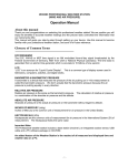
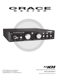
Automon User Manual Table of Contents Getting to know your product ....................................................................... 1 Vehicle Requirements .................................................................................. 2 Installation ................................................................................................. 2 Monitoring .................................................................................................. 3 Diagnostics................................................................................................. 6 Acceleration Test......................................................................................... 8 The Digital Dashboard.................................................................................. 9 The Car Details View.................................................................................. 10 Final Notes ............................................................................................... 10 ii Getting to know your product Automon is a embedded touch screen computer that run's specialised custom built diagnostic software. This product is capable of the following functions: Displaying of live data from supported OBD-II sensors in your vehicle Capturing sensor states with custom rules Retrieval of diagnostic trouble codes (DTCs) if available Resetting of Malfunction Indicator Lamp (MIL) and clearing of DTCs Testing vehicle acceleration times to custom speeds Identification of Vehicle's Identification Number and OBD Standards In figure 1, you can see the main menu bar and Automon's status bar. Navigation of Automon was designed with a touch based interface in mind. The menu on top provides easy access to the main parts of Automon with a single tap and sufficient size buttons for the average person. Any messages that Automon has to the user will be displayed using the status bar area. In figure 1 you can see the status is “Monitoring Started!”. Figure 1 – The main menu bar and status area 1 Vehicle Requirements In order to use Automon, you will need an OBD-II complient vehicle. For American vehicles, the OBD-II standard was made mandatory for all vehicles produced after 1996. However, in Europe, the European OBD (EOBD) standard was not introduced until 2001. Vehicle's that support OBDII are required to have the connector shown in figure 2. This connector is generally hidden away, usually underneath the dash. If you see this connector in your car, then there is a good chance your car supports it. However, this connector was used before OBD-II so you will have to connect Automon to confirm. Figure 2 – The datalink connector (DLC) for OBD-II vehicles Installation Installation of Automon is very simple. All you have to do is connect the diagnostic male connector into the vehicle's DLC connector shown in figure 2. Locating this connector may be difficult so please look at your vehicle's documentation. Automon is powered from the 12 volt cigerrette lighter. Simply plug in the power lead into this. Once Automon's physical connections are set, it is only a matter of starting Automon. It will look after the rest. 2 Monitoring Introduction The monitoring view is the first view that is seen when you start Automon. It can be navigated by tapping on the first menu icon labeled Monitoring. The monitoring mode allows you to view live sensor data while also supporting the addition and activation of rules. More details will be given on this below. Figure 3 – The Monitoring View/Mode Live Sensor Data Just because one vehicle supports a sensor, such as “Engine Runtime”, doesn't mean another vehicle has to. The OBD-II standard does not force manufacturers to implement all sensors – just a subset. On start up Automon intelligently discovers what sensors are available on the vehicle it is connected to and only makes these available to the user. Multiple sensors can be added to the monitor so live data can be viewed. These sensors can be added one by one by selecting the appropiate sensor from the drop down in figure 4 and tapping the Add Sensor button. Figure 4 – Adding a sensor to the monitor 3 Sensor Frequencies Automon must query the ECU for each individual sensor and wait back on a response before requesting the next and so on. Some vehicles support roughly 5 samples of a single sensor value per second. As more sensors are added, the less frequent each will get updated. Some sensors update more regulary than others. For example, engine RPM and vehicle speed change very frequent relative to something like the coolant temperature of the engine. For this reason, it would be wasteful to check up engine coolant temperature as often as engine RPM. For this reason, the concept of a sensor frequency was brought into Automon. By default all sensors get added with the default frequency of 1Hz. This means that a sensor gets updated every cycle. However, the user can change this to another value, for example 10Hz, if they only want to update the value every 10th cycle. Introduction to Rules With Automon it is possible to enable rules when live data is being monitored. A rule forms a condition from 1 or 2 sensor values. When the sensor value(s) meet the conditions set by the rule, the rule becomes satisfied and the user is notified by the satisfied rule becoming highlighted in the list of rules. Automon allows you to add multiple sensors to the monitor in order to allow the user to monitor various different sensor values/states. Creating a Rule To create a rule, the rule editor must be used. The rule editor can be launched from the Monitoring view. Simply click the button highlighted in figure 5 to enter the rule editor. Figure 6 shows a screen shot of what the rule editor looks like. Figure 5 – Button to Launch the Rule Editor The rule editor allows you to add 1 or 2 sensors to a rule. Simply tap on the drop down combo box and choose your rule. The range of values available on the slider for adapt to the sensor selected. For example, engine speed goes from 0 to 255 while engine coolant is from -40 to 215. The available operators to be chosen on a sensor can be less than, greater than, equal to and so on. When you've chosen what conditions each sensor is, you can join both using an AND or an OR boolean condition. If AND is selected, then both sensors have to be satisfied individually but if OR is selected, if one sensor's value matches it's condition, then the rule as a whole gets satisfied. To add the rule to the rule list you simply tap on the Create Rule button. Rules will remain persistently on reboot. 4 Figure 6 – The Rule Editor Deleting a Rule Deleting a rule is just a matter of selecting the rule you want to delete from the Current Rules table list and tapping on the Delete Rule push button. Using Rules Once you've created your rules in the Rule Editor, the rules will come available in the Add Rule drop down combo box in the rule management area of the monitoring screen. Rules are managed in the lower half of the monitoring view which is shown in figuure 7 below. To add a rule to the monitor, you simply select the rule you want from the drop down list and tap on the add rule button. Multiple rules can be added by selecting different rules from the drop down list. Note: For each sensor listed in the rules, the respective sensors must also be added to the monitor. To remove a rule you simply tap on the rule you want to remove and then tap on the Remove Rule push button. Figure 7 – Rule Management in Monitoring View/Mode 5 Starting the Monitor Once you have all your sensors added and any rules you would like added, you can start monitoring by tapping on the Start Monitor. Automon will only successfully start monitoring if all the neccessary sensors have been added that are required by the rules added. Adding rules is optional however, in that case any sensors can be added. Figure 8 – The button to push to start monitoring Diagnostics When an error occurs in your vehicle, the ECU logs an error code or a diagnostic trouble code (DTC) in it's memory. These codes are typically just numeric numbers that are meaningless to a user. Automon has a built in database of codes to give you a more user friendly description of what the codes found mean. If a serious malfunction occurs in the engine management system the malfunction indicator lamp (MIL) is illuminated on the dashboard. Generally this indicator light is turned off by mechanics using specialised scan tools. Turning off the MIL clears all DTCs logged and resets any information the engine learned, such as calibrating fuel consumption. Automon supports this functionality by allowing the user to clear any DTCs present as well as turn off the MIL. This is a convenient function that should only be exercised once the root cause of the problem has being detected and resolved. Figure 9 – Codes were found and the MIL was on 6 Viewing Diagnostic Codes If Automon detected diagnostic trouble codes in the engine's control unit, it will display them in the Diagnostics view. To access this, simply tap on the Diagnostics menu button on top. This view can be seen in figure 9 above. In the figure, 6 codes were present, 2 of which had no human readable meaning in the data base. Some codes are proprietary to the car so you will have to get access to these codes from your local dealer. Resetting the Malfunction Indicator Lamp (MIL) In figure 9, it is evident that the MIL is on in the current vehicle. By tapping on the Reset MIL push button, a menu will appear prompting your for a confirmation. This confirmation prompt is shown in figure 10. Clearing the MIL and DTCs is only advisable once all problems in your vehicle have been resolved. After the MIL is reset, you will see all the codes have disappeared and the MIL light turned off as can be seen in figure 11. Note: Your vehicle might run inefficiently for a few miles as the engine management system must re calibrate the fuelling mixture to get a efficient mix. This could take several miles of driving. Figure 10 – Resetting the MIL and clearing DTCs Figure 11 – View after resetting the MIL and clearing DTCs 7 Rechecking for Codes By default when Automon starts, it does a scan for DTCs. However, if you have a problematic vehicle, the malfunction indicator lamp might appear illuminated again and more DTCs logged as soon as you reset it. To check for this, you can simply tap on the Check ECU push button. Acceleration Test Automon provides a very useful function, the Acceleration Test. This allows you to test the time in which your vehicle can reach a defined speed. Figure 12 – The Acceleration Test View/Mode Choosing your Destination Speed The first step on starting an acceleration test is to define your destination speed. The destination speed is the speed in kilometres per hour you want to time your vehicle to. The destination speed can be any speed from 0 – 255KPH that is a multiple of 5. i.e.: 0, 5, 10 and so on. The destination speed can be chosen by tapping on the up and down arrows shown in figure 11. Figure 13 – Choosing your destination speed 8 Starting the Acceleration Test Before starting the acceleration test, you should prepare your car on a track in a stationary position. You then simply tap on the Start Acceleration Test push button. Automon will then wait for you to start moving > 1KPH before a timer will start. As soon as you reach the destination speed, the test will stop and the recorded time will be displayed as can be seen in figure 10. The Digital Dashboard Although the digital dashboard is a novelty feature by Automon, it can be useful if your dashboard dials give up. To start the dashboard you simply choose the Digital Dashboard menu button and on the view shown in figure 12, you simply tap on the Start Dashboard push button. The dashboard gives a dial for both the vehicle speed and the engine speed. It is important to note that how quick the dials change or respond to real time changes depends really on what OBD-II protocol your vehicle has implemented. Each dial might only get updated once every 1/3 of a second which might seem un responsive to some quick or fast revving cars. Figure 14 – The Digital Dashboard 9 The Car Details View The car details view gives a very basic few descriptions of what OBD protocol your vehicle uses as well as the Vehicle Identification Number (VIN). The VIN is also known as the chassis number of a car. It is its unique ID world wide. The VIN has encoded in it, the manufacture code, and the location of the factory that built the vehicle. Final Notes Automon cannot support the simultaneous running of modes. For example it is not possible to start monitoring when the digital dashboard or acceleration test is running. This is due to the limitation of OBD-II in that only a limited amount of sample data can be obtained by the ECU at one time. Each request has to be sent in sequence so no parallel activity can occur. We hope you enjoy your new product and if you have any problems, please do not hesitate to get in touch with us! 10