1
Final Year Project Report
An Embedded Automotive Monitoring Device
Automon
Submitted by
Donal O' Connor
Supervisor
Tim Horgan
In partial fulfilment of the requirements for the Degree of
B.Sc. (Hons) Software Development and Computer Networking
Abstract
All modern vehicles today include an Engine Control Unit (ECU). This unit is
responsible for the co-ordination of all sub systems of the vehicle such as the anti
locking breaking system (ABS) and the fuel ignition system. The ECU reads
sensor values from various parts of the engine and depending on these values it
performs the appropriate actions. For example, if the air intake is low, the fuel
input is increased to compensate. If errors occur in the engine management
system, such as a miss-fire in the engine, the ECU must log this error and if
serious enough, illuminate the malfunction indicator lamp (MIL) on the dashboard
to notify the driver. All this information is made available to scan tools and fault
code readers using the Onboard Diagnostics (OBD) protocol.
The purpose of this project, Automon, is to make this information freely available
to drivers or mechanics in an embedded touch screen device. This can give the
driver more insight into what is occurring in their car in real time. Engine tuners
often monitor sensors during a tuning session to see what affects the changes
have. Generally they would connect a laptop to a scan tool to monitor such data.
Often, they may take the car out for a spin around a track. Having a laptop in this
environment can be difficult.
Automon solves these problems by providing many useful functions such as real
time display of sensor data, diagnostic trouble code (DTC) reading and much
more. These features will be listed further on in this document. The project
contains three main components: (1) The touch screen computer,
(2) The
ELM327 OBD interface chip and (3) the actual Automon software that will work
with these devices.
- ii -
Acknowledments
First of all I would like to thank my project supervisor Tim Horgan for helping me
get started by purchasing the equipment I required for the project and for his
continuous guidance and support. I would also like to thank Vitaliy and the
Scantool.net team for generously sponsoring a ElmScan 5 scan tool that was an
essential component in this project. Another person that deserves greatly to be
acknowledged is Martin Buckley, a former employee of SnapOn for offering his
expertise with car diagnostics and his good advice.
I would also like to thank everyone in the QT and TS7000 mailing lists. The
developers on these were always very helpful when I experienced any problems.
In fact they also supported me in my choice of using QT Embedded for this
project which in the end turned out to be the correct one.
Finally I would like to thank my family and friends for putting up with my
constant moaning about the project and supporting me through the difficult
times!
- iii -
List of Abbreviations
OBD
EOBD
ISO
SAE
ECU
ECM
TCM
SBC
ARM
RISC
VIN
DTC
MIL
PID
VPW
PWM
CAN
KWP2000
RPM
KPH
DLC
MAF
SCP
SSH
IC
SA
TA
AT
RTOS
Onboard Diagnostics
European EOBD
International Standards Organistion
Society of Automotive Engineering
Engine Control Unit
Engine Control Module
Transmission Control Module
Single Board Computer
Advanced RISC Machine
Reduced Instruction Set Computer
Vehicle Identification Number
Diagnostic Trouble Code
Malfunction Indicator Lamp
Parameter ID
Variable Pulse Width
Pulse Wave Modulation
Controller Area Network
Keyword Protocol 2000
Revolutions Per Minute
Kilometers Per Hour
Datalink Connector
Mass Air Flow
Secure Copy
Secure Shell
Integrated Circuit
Source Address
Target Address
Adaptive Timing
Real-time Operating System
- iv -
Table of Contents
Introduction ................................................................................................ 1
Overview ................................................................................................ 1
Project Motivation .................................................................................... 3
Aims and Objectives ................................................................................. 4
Minimum Requirements ............................................................................ 6
Report Structure ...................................................................................... 6
Project Management .................................................................................... 8
Project Schedule ...................................................................................... 8
Changes to Project Schedule ................................................................... 10
Project Diary ......................................................................................... 10
Background and Further Research ............................................................... 12
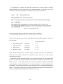
Onboard Diagnostics (OBD) ..................................................................... 12
The TS-7390 Single Board Computer ........................................................ 19
The ELM327 Integrated Circuit ................................................................. 22
Cross Compiling and Toolchains ............................................................... 28
ECU Simulation Tools .............................................................................. 30
Existing Solutions and Potential users ....................................................... 32
System Design .......................................................................................... 34
High Level Architecture Design................................................................. 35
Modular Decomposition ........................................................................... 36
Human Computer Interaction (HCI) Design ............................................... 42
Class Diagrams ...................................................................................... 43
Implementation and Deployment ................................................................. 46
Choice of Programming and Tools ............................................................ 46
Development Environment ...................................................................... 48
Project Iterations ................................................................................... 49
Iteration One: Prototype on TS-7390 .................................................... 49
Iteration Two: The Automon Kernel ....................................................... 53
Iteration Three: The Graphical User Interface ......................................... 57
Threading and Process Priority ................................................................. 58
Tslib and Configuring the Touch screen ..................................................... 60
Deployment of QT Embedded on TS-7390 ................................................. 62
Starting Automon Automatically from Bootup ............................................ 63
Evaluation and Testing ............................................................................... 64
Testing Methodology............................................................................... 64
The Test Plan ......................................................................................... 65
Third Party Evaluation............................................................................. 67
Test Results........................................................................................... 67
Code Reviews ........................................................................................ 68
System Limitations .................................................................................... 69
Performance .......................................................................................... 69
OBD-II’s Response Time ......................................................................... 70
Error Handling and Recovery ................................................................... 70
Functionality Limitations ......................................................................... 71
Problems Encountered and Solutions............................................................ 72
The TS-7390’s Frame Buffer and QT Embedded 4 ....................................... 72
Rover/MG’s DLC Problems ....................................................................... 74
Dropping of Characters Sent by ELM327 ................................................... 75
Conclusions and Future Enhancements ......................................................... 77
Future Enhancements ............................................................................. 77
Freeze Frame Support ......................................................................... 77
Data Logging ...................................................................................... 78
-v-
Improved Rule System ........................................................................ 78
On-Screen Keyboard ........................................................................... 78
GPS Support ...................................................................................... 79
Fuel Economy Monitoring Features ........................................................ 79
Conclusion ............................................................................................ 80
Bibliography ............................................................................................. 81
- vi -
Chapter 1
Introduction
Overview
Vehicles today are much more intelligent than they were years back. The
traditional vehicle timed the ignition of the spark using mechanical distributors
[1]
.
This method of co-ordinating the timing of the spark delivery when the fuel and
air mixture were compressed in the engine cylinders wasn’t ideal. Due to the
fixed nature of the mechanical setup, it was very difficult to get optimum fuel
combustion resulting in the most efficient power output.
Fortunately modern engines are controlled electronically using real time
software in a device known as the engine control unit (ECU)
[2]
. This allows the
car to adapt to environmental conditions such as air density in order to increase
the combustion efficiently subsequently improving fuel economy. The ECU
controls many other sub systems of the engine such as, for example, the antilocking braking system (ABS). All decisions made by the ECU are based on the
state of sensors that are placed at various places throughout the vehicle primarily
around the engine bay.
As years went on, the ECU became more capable of supplying diagnostic and
sensor data to help mechanics identify the source of problems that arise in the
engine management system. Eventually a standard was created that all
manufacturers were encouraged to follow. The standard became commonly
known as Onboard Diagnostics (OBD)
[3]
. The introduction of the standard was in
an effort to encourge vehicle manufacturers to design more reliable emission
control systems. OBD-II is an enhancement of the OBD standard that was
introduced later and made mandatory
[4]
.
-1-
Generally data is not obtained from the ECU until a problem arises in the
engine management system. The purpose of this project was an attempt to use
this data to provide useful features and functionality to the car enthusiast that
tunes his engine or a mechanic for easily monitoring engine behaviour.
Automon connects to the ECU using a special integrated circuit, the ELM327
[5]
.
This chip or IC is responsible for the low level timing and signalling to and from
the ECU’s communication bus. It simply connects to the OBD-II standard SAE
J1962
[6]
physical datalink connector (DLC). The embedded computer that
Automon runs on is then connected to this chip over a serial interface.
Automon is specialised software that runs on an embedded touch screen
computer. The computer is powered by an ARM processor and runs embedded
Linux. Automon’s software runs on top of the embedded Linux distribution to
provide a useful touch screen application to the user of the device. This software
allows the user to monitor any sensors available on the vehicle, obtain diagnostic
data when an error occurs as well as providing other useful functionality such as
acceleration tests, digitial dashboards etc.
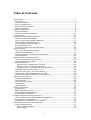
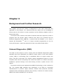
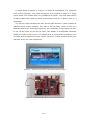
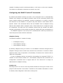
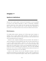
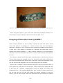
The computer that runs Automon is known as a single board computer (SBC)
[7]
. These are computers that have a single circuit board in which all components
such as the CPU, RAM and Flash memory are present. The computer with
Automon running can be seen in figure.
Figure 1.1 – Automon running on the single board computer (SBC)
-2-
Project Motivation
For many years I’ve had a keen interest in cars. I bought my first car about 5
years ago and ever since then I have been fasinated by how engines work. This
combined with my main interest in computers and technology formed the basis of
my decision on chosing this topic for my final year project.
I always knew how the combustion engine worked from a mechanical
perspective but never really understood how everything was controlled to such a
fine precision. This sent me on a quest to discover exactly how the engine control
unit (ECU) contributes to the task of running an engine. After a bit of research
into ECUs, I stumbled upon a standard known as Onboard Diagnostics (OBD)
[3]
.
Directing my research down the OBD route opened up a world of ideas to me. I
had no idea so much information was available from an ECU.
At the time, I was on placement working in Intel’s R&D centre in Shannon and
was surrounded by embedded development and Linux. This got me thinking if I
was capable of buidling an embedded device that would connect to the the ECU
via the datalink connector (DLC) or diagnostic connector
[6]
. It was then that I
discovered that it may actually be possible to develop engine monitoring software
that runs on an embedded touch screen device.
However just having an interest in these areas was not the only motivational
factor behind my decision on chosing this project. Vehicles today are getting
more technologically equipped and more and more software is becoming
responsible for powering them opening up new exciting services to the driver.
This is especially true for the next generation eletric or hydrogen cell powered
cars. BMW are even talking about developing an open-source in-vehicle platform
[8]
that allows software developers to interface with the vehicle and provide a
better journey experience for the driver. Oil is running out quick and vehicles will
start moving away from the conventional combustion engine. I personally predict
that there will be a surge of software development opportunities in the
automotive industry towards the near future.
It is true that this project only deals with OBD-II which is based only on the
traditional engine so what I do might not be of any relevence to the next
generation vehicles. It does however provide me with an insight to what is
involved in building an embedded computer that runs specialised software.
Linux is becoming a key player in the embedded systems market due to its
open source nature and reliable kernel. Producing a project that worked with
-3-
embedded Linux was something I wanted to do ever since I was on placement in
Intel. Everything that was developed in there was powered using Linux. I can see
Linux becoming the bedrock for all embedded systems in the future. They have
even created an embedded system the size of a RJ45 connector
[9]
so it looks like
Linux can be used anywhere including controlling electronics in cars as seen
earlier!
Aims and Objectives
The aim of this project is to get a fully functional single board computer (SBC)
working with custom built monitoring software that communicates with all
modern vehicles. It should be capable of extracting the neccessary data from the
vehicle's engine control unit (ECU) in order to use it in a meaninful and useful
way. Communication to and from the ECU will be done using the Onboard
Diagnostics two (OBD-II) standard. In theory, by using this standard, Automon
should work with all modern vehicles that comply with the standard.
The software that will run on the device will have to be able to work with the
hexadecmal replies that the ECU returns on requests of data. The communication
with the ECU will have to be handled using a polling type method as data
interrupts or automatic updating of data from the ECU cannot be done
sporadically. Instead a cyclic process or thread will have to run continuously to do
a query to the ECU followed by the reading of the reply. The software will have to
work with the returned hexadecimal data in a way that provides the user or driver
useful functionality.
The objectives of this project are as follows:
§
To communicate with the ECU of a vehicle indirectly with the help of an
integrated circuit, the ELM327
[5]
which will handle all the low level bus
communication with the ECU using what ever signalling method the
vehicle uses. There are five OBD-II signalling protocols in total and the
ELM327 supports all 5 including CAN. The communication with the ELM327
will be done over serial so the Automon software should be able to time
everything properly.
-4-
§
To get the QT for Embedded Linux C++ [7] framework successfully cross
compiled
[10]
for the ARM architecture so that it will run on the single board
computer that the Automon software will be deployed on. The cross
compilation of QT will also have to be compiled in such a way that it is
configured to use the Tslib
[11]
touch screen library. The Tslib library will
also have to be cross compiled and configured on the device.
§
To configure the embedded Linux distribution, Debian Etch that comes
with the SBC in such a way that X11 GUI service will be removed and the
bare minimum services started. The configuration should start Automon
automatically on start up of the device. The rendering of the application to
the screen will be done by writing directly to the Linux frame buffer device.
§
To implement a design in which multiple vehicle sensors such as engine
RPM or engine coolant temperature can be monitored simultaneously.
Every sensor has its own equation or formula
[12]
that is applied to the
returned data bytes from the ECU. An important design consideration is to
provide a convenient way of adding new sensors to Automon with the
minimum amount of number of lines of code. This will make Automon
extensible by providing easy addition of new sensor types when they
become available in the future. As a bonus, a priority based system should
be implemented where some sensors get updated more frequent than
others. For example the engine RPM is a high priority sensor as it changes
more frequently than the engine coolant temperature.
§
To create a rule based system for the monitoring of sensors. This will allow
conditions to be created during the monitoring of sensors. When the
condition becomes true or is satisfied, the rule should alert or notify the
user. A rule might be “Engine Coolant Temperature is less than 40 and
Engine RPM is greater than 4000”. When Automon is monitoring these two
sensors, engine RPM and engine coolant temperature, it should alert the
user when these sensors change in such a way that the condition becomes
true.
§
To implement support for reading diagnostic trouble codes (DTCs) from
the ECU when a problem is logged due to engine problems. A DTC
database of codes should be present on the device to map DTCs to human
readable explanations of these codes. Another objective in this area is to
-5-
support the turning off of the malfunction indicator lamp (MIL) and
clearing of DTCs present on the ECU.
§
To create a digital dashboard on the device that includes dials such as
engine RPM and vehicle speed to represent these parameters.
§
To create a touch screen friendly GUI that implements good HCI practices
such as reducing the number of taps that a user has to do in order to
perform a specific task.
Minimum Requirements
The following are the minumum requirements for this project:
§
Implement software that is capable of communicating with the ECU
indirectly using the ELM327 IC in order to read any sensors available on
the vehicle that Automon is connected to. It should also be able to
continuously poll the ECU to update sensor values in real time.
§
To read diagnostic trouble codes from the ECU’s flash memory when
available and to provide the functionality of clearing these and resetting
the engine malfunction indicator lamp (MIL).
§
To get this custom built software cross compiled and running on the
embedded computer with the touch screen interface supported.
Report Structure
The remaining of this report is organised as follows. Chapter 2 is a short chapter
that descibes how project management was handled. Chapter 3 will describe
background information on the techniques and areas worked on in this project.
This is information that is required to be read in order to have an idea of what the
chapters that follow refer to. Included in this chapter is the extra research that
was carried out. Chapter 4 discusses briefly the design of Automon. Chapter 5
describes how testing was performed and what types of test cases were run with
the results as well. The following chapters describe problems and limitations to
-6-
the system as well as major problems I encountered during the life cycle of this
project. Chapter 9 finalises the report with my conclusion of this project any any
future enhancements that may potentially be implemented.
-7-
Chapter 2
Project Management
Project Schedule
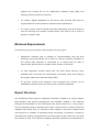
In the research phase of our project last semester, a requirement and deliverible
was a proposed project schedule. At that stage we had hardly no insight into
what was actually ahead of us. I knew at the time that producing a project
schedule that early was a major risk. An overview of the original project schedule
is shown in figure 2.1.
Figure 2.1 – Overview of Original Project Schedule from Semester 1
After the semester one exams around the middle of January, I evaluated the
schedule before I began implementation. The order of things didn’t seem logical
to me. First of all I had no idea how I was going to implement serial
communication but this was one of the first items on the project schedule list. I
done some investigation into this and I quickly stumbled across a serial I/O QT
wrapper class
[13]
that can be used at a high level of abstraction. However since it
was using QT, this framework would first need to be installed on the actual single
board computer before actually testing a serial I/O prototype on it.
-8-
These changes of steps and increments of the project led me to revise the
entire schedule to make it a bit more logical and set well defined mile stones that
need to be achieved before continuing to the next.
Milestones
The following are the major milestones that I decided needed to be met within
the defined time frames if the project was going to be a success meeting all the
aims and objectives.
§
Milestone 1: Get QT Applications Executing on SBC
This is one of the critical milestones of this project. Without having QT
working on the embedded SBC, the project would be a major failure. All I
will be left with is software that only runs on a standard desktop or laptop
computer which is only part of what is involved with this project.
Before coding starts, this is the mile stone that needs to be achieved first
to prove the concepts used later will work. It is too much of a risk to
develop the application first and then attempt to deploy it later on the SBC.
§
Milestone 2: Build Core Communication Functionality (Kernel)
Before any GUI work is done, it is critical to get the functionality of the
project implemented first at a console level. The idea of the kernel is to
handle all serial I/O communication and develop an architecture that
enables Automon to be easily extended. Once this is developed, I can
progress to milestone 3, the development of the actual GUI
§
Milestone 3: Development of GUI
Even though having the SBC communicating successfully with the vehicle’s
ECU is a good chunk of what this project aims to accomplish, it would not
be complete without a fully functional GUI to demonstrate the functionality
that was developed in milestone 2. The GUI development phase includes
the deploying of the entire application to the SBC.
§
Milestone 4: Device Configuration and Testing
Once everything has been developed, it is time to do testing and configure
the device in such a way that it boots automatically on start up and all
unnecessary start up services of Linux, such as X11 are removed. Even
though testing has its own milestone at the end here, it does not mean
that testing wasn’t done at a unit level throughout the project life cycle.
-9-
Changes to Project Schedule
It was evident that the original project schedule was not suitable so a complete
revision was done. The mile stones listed above formed the basis for creating
micro level tasks that needed to be completed. Clearly it isn’t possible to list all
micro level tasks here so instead I will list the activities that encapsulate all these
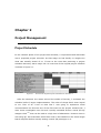
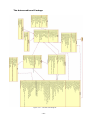
tasks. The revised project schedule can be seen in figure 2.2. This had been
modified continuously due to changes and unforeseen events.
Things changed dramatically in March when I became ill and got sent to
hospital for the good part of a week. Recovery time took another week so in total
I lossed about two weeks on my schedule. A small re-scoping of the project
occured at this stage where one of my requirements – displaying of freeze frame
data on the ECU – had to get excluded from the final release. Becoming ill is
however one of the major risks for a final year project as only a single human
resource is available.
On top of this, assignment deadlines all came together towards the end around
April so this created some fustration but everything worked out okay in the end.
Figure 2.2 – Overview of Original Project Schedule from Semester 1
Project Diary
As a requirement for the project, we were asked to keep a project diary so that
by looking back it is easy to see what progress we were making on our project at
a specific time. Instead of typing it up on a document and saving it to disk, I
thought it would be a better idea to create a blog and place my daily/weekly
- 10 -
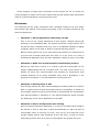
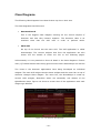
entries in it so that the public can see. My blog proved to be very helpful to some
individuals that required help with setting up QT on the TS-7390 single board
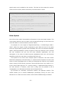
computer. It also got a lot of employers interested in my project as well.
The project blog can be found at
http://automon.donaloconnor.net
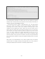
A screen shot of the blog is shown in figure 2.3
Figure 2.3 – My Project Diary/Blog @ http://automon.donaloconnor.net
- 11 -
Chapter 3
Background and Further Research
This chapter will give the reader a background in the main areas that are
applicable to this project. It is assumed that the reader has no knowledge of
these areas so this section is quite important as the following chapters refer to
these areas often.
This section also contains new areas of research that were required in order to
progress with the project. Major research time had to be invested into the
Onboard Diagnostics two (OBD-II)
learned QT Embedded
[14]
[4]
protocol and the ELM327
[5]
IC. Since I
and C++ object oriented programming on the fly
during this project, it was also essential to learn more about these topics.
Onboard Diagnostics (OBD)
The heart of this project is tied in closely with the Onboard Diagnostics (OBD)
standard and more specifically the OBD-II version which is the most modern
version. OBD is a technology that is embedded within an engine control unit
(ECU). The ECU is the heart of a vehicle’s engine management system. It is the
computer that controls everything from when the brakes of a vehicle are briefly
disabled to prevent locking to the exact timing of when a spark occurs in the
engine.
All modern vehicles must implement the OBD-II technology in their vehicles by
law. The original OBD standard was developed in an effort to encourage
manufacturers to produce highly efficient vehicles that produced minimum
emissions while maintaining optimum fuel economy. However the newer version,
OBD-II was made mandatory on all vehicles.
- 12 -
The OBD technology benefits motorists, technicians and mechanics by
providing them with useful information, such as the state of certain parts of the
engine management system. This allows them to quickly identify the sources of
problems and guide them on the correct path to repairing. Several different
methods of diagnosing are available. If the ECU discovers a fault in some system,
it logs a diagnostic trouble code. If the mechanic wants to monitor sensors in real
time it can do so by looking up the relevant sensor value using scan tools. These
concepts are explained below.
History of OBD
In 1970, the US government congress passed the Clean Air Act
[15]
. Vehicles were
a big contributor to pollution in the air. This called for a new standard to be
introduced, the OBD standard. The standard itself was developed by the Society
of Automotive Engineers (SAE) during the late 1980’s. At the time some
manufacturers had their own proprietary monitoring and reporting systems but
specialised tools were required in order to read this information. OBD was the
first standard of its kind, however it was not mandatory. Its main purpose was to
encourage manufacturers to create more efficient engines, thus leading to
reduced emissions and better fuel economy.
However, the first OBD standard was not perfect; it had a lot of problems,
primarily the following:
§
The data link connector (DLC) in which scan tools would connect to in
order to interface with the ECU was not standardised. This prevented
generic scan tools being manufactured that would work with all vehicles.
§
Each vehicle manufacturer had its own unique set of diagnostic codes for
identifying errors in the engine management system. This was another
major problem for creating generic diagnostic hardware.
§
The type of information stored on the vehicle’s ECU was different from
manufacturer to manufacturer.
These problems led to the development of a newer standard that would
combat these issues and provide better standardisation.
OBD-II was developed in 1996. It supported better standardisation to the areas
in which the first version of OBD failed. A standard physical data link connector
- 13 -
was made mandatory by the specification. The connector
[6]
is defined by the
J1962 standard that the SAE specified. This new standard DLC allowed diagnostic
hardware manufacturers to produce generic hardware that worked on any
modern vehicle. Diagnostic trouble codes (DTCs) were made standard however
manufacturers were still allowed to include more detailed proprietary ones. Four
categories of codes were introduced for different areas of the vehicle. These code
types are discussed further in the coming sections.
OBD-II still has its down falls however. It contains many different signalling
protocols at the electrical level. Each of these can handle different bus speeds and
initialisation speeds can vary dramatically across some. In one protocol you might
be able to read five samples of a sensor value per second while using better
protocols such as
CAN
[16] you might obtain 20 samples per second. In 2008, it
was made mandatory for all vehicles produced after this year that they use the
ISO 15765-4 signalling protocol (CAN). This provides much better data rates.
CAN isn’t a new technology. It has been around since the 1980’s but it is only
recent that the manufacturers are developing modular sub engine systems that
communicate over a CAN bus.
European OBD
The European OBD standard or EOBD
[17]
is Europe’s implementation of OBD-II. It
is pretty much the same as OBD-II but only with a different name. Generally it
uses preferred signalling protocols. Where ever I refer to EOBD in this document,
I am really talking about OBD-II.
It was in 1996 that the OBD-II standard was made mandatory all vehicles
manufactured in America. However it was not until 2000 that EOBD was made
mandatory on all petrol vehicles manufactured in Europe. In 2003 it was made
mandatory on all diesel powered vehicles.
The Signalling Protocols
OBD-II has different implementations of how signalling at a low level occurs.
There are in total 5 being used by manufacturers today. The 5 are:
§
J1850 PWM
§
J1850 VPW
§
ISO 9141
- 14 -
§
ISO 14230 (KWP2000)
§
ISO 15765-4 - Controller Area Network (CAN)
ISO 9141 and ISO 14230 (KWP2000) are electrically equivalent. They are
generally used in European vehicles where the EOBD standard is used. For
example, Peugeots and MG/Rover vehicles use KWP2000. Some modern MG’s use
the ISO 9141 standard which is essentially the same. This is due to a change of
ECU in the versions.
OBD-II Modes and Parameter IDs (PIDs)
A parameter ID (PID) is a unique code or command that OBD assigns to a specific
data request type. So in order to communicate with an ECU using OBD-II, you
must first send the appropriate PID for the type of information you want and the
ECU will then respond with a sequence of bytes. The bytes are usually expressed
in hexadecimal format.
The OBD-II standard does not require vehicle manufacturers to implement all
PIDs. In fact, it doesn’t even give a minimum for some modes such as Mode 1
and Mode 2 PIDs. However, most manufacturers implement the most common
ones such as vehicle speed and engine RPM.
Since there are different categories of requests, the OBD-II standard breaks
the PIDs up into groups, known as modes. In the original J1979 specification
document of the SAE, it listed 9 diagnostic test modes. They are as follows:
§
Mode 1: PIDs in this category display current real time data such as the
results of the engine RPM sensor.
§
Mode 2: When a fault or malfunction occurs, a snap shot of all mode 1
sensors are taken. This snap shot is known as a freeze frame. To access
each individual sensor, you use the mode 2 requests.
§
Mode 3: Sending a mode 3 request, the ECU responds with a list of DTCs
stored if any.
§
Mode 4: Sending a mode 4 request, the ECU clears the DTCs stored and
turns off the malfunction indicator lamp (MIL) if on.
§
Mode 5: Test results from oxygen sensor monitoring
§
Mode 6: Test results from other types of tests
§
Mode 7: Show pending Diagnostic Trouble Codes
§
Mode 8: Control operation of on-board system
- 15 -
§
Mode 9: Responds with the vehicles identification number (VIN).
Since the original specification, other modes have been added on and a lot are
manufacturer specific.
To send a request to the ECU you must specify the mode and the PID. So for
example, if I want to view the current engine RPM, I would send a 010Ch
(hexadecimal) query to the ECU. The ECU would then respond with a few bytes of
data for the response. If I wanted to see the engine RPM stored value when a
fault occurred last on the vehicle, I would instead send a mode 2 query, 020Ch.
As you can see the query or command to send to an ECU is a combination of
the mode and the relevant PID. All requests must adhere to this request format.
How data is sent on the ECU bus
Naturally the data isn’t sent to the ECU bus in raw bytes having just the mode
and the PID thrown on the wire. The message (mode and PID) is encapsulated in
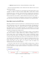
a header and footer. Figure 3.1 shows the format of a typical OBD-II message.
Since OBD-II works on a bus based technology, the identification of source and
destination need to be accounted for. Without it the scan tool would never be able
to locate the message that is destined for it.
The header format includes 3 fields, a priority field, a sender or source address
(SA) and a receiver or target address (TA). OBD-II’s messaging works on a
priority based scheme. Some messages within an engine’s management system
are more critical than others. For example, communication with the ABS system
is critical and that should always get priority over something like a scan tool or
even Automon! Our message such as 010C is placed in the payload section of the
packet. Normally this is just 2 bytes; the mode and the PID but some PIDs
require extra data to be sent after it so 7 bytes in total are allowed. The
checksum at the end is to ensure integrity.
It should be noted that this is the normal OBD-II message format. CAN has
extra fields placed in it as it is a more complex protocol capable of transferring a
lot more information at higher speeds. Discussion on this protocol is out of scope
for this project.
Figure 3.1 – The format of an OBD-II message
- 16 -
Interpreting OBD-II Responses
The data returned from the ECU is in the form of a series of bytes. The response
can either be bit encoded or simply value based bytes, however generally a
formula must be applied to the bytes in order to decode the actual response in a
human understandable format.
The actual response is located by the scan tool by looking at the target address
field of the header. Scan tools normally have an address of F1h.
For decoding mode 1 and 2 sensor type PIDs, the result is generally a simple
one that is obtained using a formula on the few bytes returned in the payload
field, usually 2 or 4. Others however are a bit more complex with a bit of logic
included. For example: if byte A equals X, then byte B means Y.
There is no generic way of working with returned data. All PIDs have their own
way of dealing with the returned data. However the following are examples of
what a bit encoded response and a regular mode 1 response might look like.
The following two examples are simple sensor type responses.
Figure 3.2 – Converting returned bytes for engine coolant request
Figure 3.3 – Converting returned bytes for an engine RPM request
- 17 -
The following is a bitwise encoded PID response for a 0101 request. This PID
includes details on how many DTCs are presently stored on the ECU and if the
malfunction indicator lamp (MIL) or engine check light is illuminated.
Figure 3.4 – Bit encoded example
Interpreting Diagnostic Trouble Codes (DTCs)
There are four main types of DTC codes defined by the SAE standards. These are
the following:
First digit will be:
•
Powertrain Codes
(P codes)
0-3
•
Chassis Codes
(C codes)
4-7
•
Body Codes
(B codes)
8-B
•
Network Codes
(U codes)
C-F
These codes identify where or what system the fault occurred. The powertrain
codes are the most common and represent codes that occur in the engine
management system.
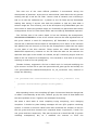
Diagnostic trouble codes are made up of 5 digits. The digits are in hexadecimal
format. The first digit always identifies the type code whether it a powertrain code,
body code etc.
In the above list, you can see the range of digits that identify
what category of codes it belongs to. The other 4 digits in the code identify other
information. For example the second digit identifies if it is a standard SAE defined
code or a proprietary while the third digit identifies what system caused the fault.
Below is a diagram that illustrates the format of a code.
- 18 -
Figure 3.5 – Example of a Diagnostic Trouble Code
The description for the code above is “Evaporative Emission Control System Vent
Control Circuit Open”. You can see that it is a powertrain code that is a standard
code defined by the SAE. The third digit represents the sub system in which the
code belongs to, the auxiliary emission control system in this case.
The ECU responds with 4 hexadecimal bytes for each code. The first byte is
responsible for parts A and B in the code above. The table below shows the
conversion of these. If 0 is the first hexadecimal byte, then this represents “P0”
of the code above. If it is 1, it represents “P1” and so on. For body codes, if the
first code is 8, then this means “B0” where as if it were B, it would represent “B3”.
The list in the previous page gives the ranges of the first digit for each type of
code.
This concludes the most important parts of OBD-II that I needed to further
research in order to gain an understanding of how to work with it.
The TS-7390 Single Board Computer
One of the main objectives of this project was to get the monitoring software I
built running on an embedded system. During the research phase in semester
one, investigation was carried out in order to find a device that would be best
suited for Automon. In the end, the TS-TPC-7390 seemed the best suited.
The TS-TPC-7390 or commonly referred to as just the TS-7390 is an ARM
powered single board computer (SBC) developed by Technologic Systems in the
US.
- 19 -
A single board computer is a device in which all components of a computer
such as the processor, ram, flash storage etc are soldered or fixed on a single
circuit board. This makes them very compact and ridged. The solid state nature
of SBCs make them ideal for harsh environments such as a factory floor or a
warehouse.
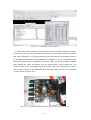
The TS-TPC-7390 includes more than just the SBC however; it also includes an
onboard touch screen interface. The SBC is the TS-7390, which is sold as a
separate product by Technologic Systems. The remainder of this report will refer
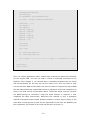
to the TS-TPC-7390 as just the TS-7390. The display is an 800x480 resolution
WVGA TFT colour touch screen. The screen itself is conveniently mounted on the
TS-7390 with an aluminium frame. Figure 3.6 and 3.7 show a photo of the front
and back of the TS-7390 respectively.
Figure 3.6 – The front of the TS-TPC-7390 with its aluminium frame
Figure 3.7 – The TS-7390 SBC at the back powering the device
- 20 -
The SBC is powered by Debian Etch, a special distribution designed for embedded
systems. It came pre-compiled for ARM and was placed on the NAND onboard
flash as well as on the SD card that came as part of the development kit. The
following sections will discuss more detailed topics of the TS-7390 that were
required to be understood to use the computer.
Interfacing with the TS-7390
In order to begin development with the TS-7390, it is important to interface with
it properly. There are many ways to connect to the computer, however not all will
be available at times.
The TS-7390 has two different modes of operation, the fast boot mode and the
normal boot. By default the TS-7390 is configured to automatically start in fast
boot mode where it can load Linux in just under 2 seconds. Unfortunately this fast
boot mode boots the system up in a read only state and disables services such as
SSH and FTP. In order to boot into the normal mode from the fast boot mode, a
dumb terminal or terminal emulator such as hyper terminal must be connected.
The console device in the Linux configuration is configured to output to the
ttyAM0 port which by default will not exist. The two UART serial ports on board
are configured on ttyAM1 and ttyAM2. ttyAM0 refers to the special development
console board that must be connected to the JTAG
[18]
connector of the board.
The JTAG connector is shown in figure 3.8. It is a special connector that is
used during the development stages for debugging purposes. The ARM processor
has certain pins dedicated to this connector so by connecting to this, you have
direct access to the CPU for debugging.
The development board that connects to the JTAG connector is the TS-9440B
sold as part of the development kit by Technologic Systems. The serial cable can
then be connected to this onto a regular PC running a terminal emulator. From
there, you can type the exit command to start booting the normal mode. This
takes about a minute. It is possible to set it so this mode starts by default when
the device is powered on. This is explained in later stages in the implementation
chapter.
- 21 -
Figure 3.8 – The JTAG connector highlighted on the TS-7390 SBC
Once in the normal mode, regular services such as SSH, FTP and telnet are
running by default. It is only a matter then of connecting to the eth0 RJ45
connector and configuring the PC on the same subnet as the TS-7390 is
configured for. By default, the TS-7390’s eth0 port is configured with the IP
address of 192.168.0.50/24.
The most valuable service running on the board is SSH. This can be used to log
into the board and also copy files over using the Secure Copy Protocol (SCP)
running over SSH.
The ELM327 Integrated Circuit
The OBD-II interface of vehicles in which test tools connect to is not directly
compatible with PCs or any general computer hardware. The biggest problem is
the fact that there are several different OBD-II communication protocols. Not only
does each of these protocols contain different message formats but they also are
different at an electrical signalling level.
Doing the necessary signal conversions from these protocols to serial on a PC
would require additional circuitry to be developed. Not only would the challenge
be out of scope of this project but I would be limiting myself to a specific protocol.
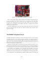
The ELM327 is an integrated circuit (IC) that was developed to solve this
problem and act as a bridge between regular RS232 serial ports and the onboard
diagnostic ports. Even though being just developed for the hobbyist, the ELM327
is a full featured IC that automatically handles all OBD protocols including the
- 22 -
latest CAN versions that newer vehicles must use by including an onboard CAN
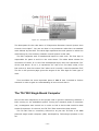
controller I/O chip. Figure 3.9 illustrates a block diagram representation of the IC.
Figure 3.9 – Block diagram of the ELM327 Integrated Circuit
The ELM327 is communicated to by sending ASCII commands over the serial
port. It supports AT type commands for configuration of the actual IC. It has on
board memory in order to keep any changes persistent. Changes may be setting
the timeout interval for receiving messages from the ECU. If the ELM327 receives
none AT type commands, it assumes that it is a request that is destined for the
ECU in which it is connected to. Before sending the data to the ECU, the ELM327
ensures that the request conforms to OBD-II standards defined by the SAE. If the
ELM327 does not understand a command, it simply replies with a single question
mark.
The ELM327 acts as a command line interface (CLI). It will always produce the
prompt character ‘>’ after any response it sends back to the serial port of the
computer connected to it. Commands will not be executed by the IC until it reads
a carriage return or line break. This character is configurable however using the
AT command type communication mechanism.
The following sections will give more detail on areas of the ELM327 that
needed to be investigated and understood in order to successfully implement the
requirements of this project. The first section describes a recommended circuit
that is required in order to power and connect to the ELM327.
- 23 -
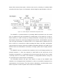
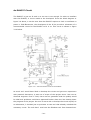
An ELM327 Circuit
The ELM337 is just an IC and it on its own is not enough. In order to interface
with the ELM327, a circuit needs to be developed. From the block diagram in
figure 3.9 above, it can be seen that the ELM327 requires a clock or oscillator to
power it. ELM Electronics, the developers of the IC do provide a schematic of a
recommended circuit for the ELM327 to fit in to. This circuit is shown in figure
3.10 below.
Figure 3.10 – A Recommended Circuit for the ELM327
As much as I would have liked to develop this circuit and get more experience
with practical electronics, it was out of scope of this project since I am not an
electrical engineer. Even if I did, there was no guarantee that the quality would
be ideal and problems could have appeared further down the line slowing down
the progress of the project. So since it was a risk to develop the circuit myself, as
an alternative, I decided just to purchase a scan tool that already included this
necessary circuit. The tool that I used was the ElmScan tool from Scantool.net.
- 24 -
These are the primary sellers of scan tool hardware that includes the ELM327 IC.
However the one they sent to me was a USB version. Luckily, the TS-7390
includes 2 USB ports and the necessary kernel drivers to support the FT232RL
USB to serial chip that is present on the ElmScan tool in order to communicate
with the ELM327’s through its serial based interface.
Connecting to the IC
The most straight forward way to communicate with the ELM327 is to use a
terminal emulator such as hyper terminal. This allows easy sending of commands
to the IC while receiving the responses in text. This is useful for debugging or
getting an idea of what is available. However, this alone is not very useful. The
data returned by the ECU via the ELM327 is represented in hexadecimal format.
The normal user would not benefit from this. Automon looks after this low level
communication automatically providing a highly user friendly GUI interface so
that users can view real time data or diagnostic trouble codes for diagnosing
problems.
As with all serial communication, certain parameters must be set in order for
communication to occur. These include the data, parity and stop bits as well as
the baud rate. These parameters are listed in figure 3.11. The newer versions of
the ELM327 include support for high baud rates such as 38400 but this generally
will not improve how fast data can be obtained from the ECU as the OBD-II
protocol is a limiting factor. The different baud rates are configured physically by
the circuit. The ElmScan 5 includes a jumper that can be set in order to change
from the default 38400 baud to 9600 baud.
Figure 3.11 – Serial Configuration Parameters for ELM327
Communication with the ECU using ELM327
In order to communicate with the ECU, you need to use OBD-II commands as
discussed in the OBD section above. If a command sent to the ELM327 does not
begin with the letters ‘A’ and ‘T’ (not case sensitive), then it will assume that the
- 25 -
command is an OBD-II one that is destined for the ECU. It will however, do
validation testing to ensure that the command makes sense.
As discussed previously, OBD-II is a messaging protocol that requires a header
and footer to be added to the command. The ELM327 conveniently looks after the
data encapsulation automatically by adding the necessary physical addresses and
generating a checksum for the FCS field in the footer.
To send an OBD-II command to the ECU, you simply send the ASCII
equivalent to the mode number concatenated with the parameter id (PID). For
example, in order to view the current engine coolant temperature, a mode 01 and
PID 0C is required. To send this to the ECU in order to receive a response, you
simply send the ASCII string ‘0105’ to the ELM327. The ELM327 will then
encapsulate this data in the payload field of an OBD-II message and send it on
the ECU’s communication bus. When the ECU is ready, in that it has looked after
high priority messages on the bus, it places a series of bytes on the interface
representing its OBD-II response message that again includes the necessary
header and footer. The ELM327 will wait until it locates the message, identifying it
by the destination or target address (TA) in the header field. It will then do a
checksum and if correct, extract the payload bytes and send it back to the serial
port in the form of ASCII characters that represent the hexadecimal data followed
by a ‘>’ prompt character to signify the end of the message.
When the ELM327 places the OBD-II command on the ECU bus, it waits a fixed
time for the message (even if the ECU sent all data) in case more is to follow. If
no data is returned, the ELM327 will send a “NO DATA” message back to the
terminal connected to it. A “NO DATA” could result in an OBD-II PID request that
is not supported by the ECU. This is quite common as different ECU’s support
different PIDs. However, if the ECU does reply, the ELM327 stays waiting in case
it receives more bytes from the ECU. This causes a lot of time to be wasted so
newer versions of the ELM327 were enhanced with an adaptive timing (AT)
feature. Adaptive timing is a feature where the ELM327 learns over time how long
to wait around for the ECU. This adaptive timing feature is configured using the
AT commands as discussed below.
Another feature that enables quicker response times from the ELM327, is
where it can accept a expected byte number from the request sent to it. For
example, the response for an engine coolant RPM value from the ECU results in 4
bytes being returned. The ELM327 allows you to specify the command followed by
the expected number of bytes. For example, we would now send “010C 4”. Once
the ELM327 receives the 4 bytes, it will know that no more should be expected so
- 26 -
instead of waiting around as discussed above, it will return to the user instantly.
This feature is exploited in Automon and works very well.
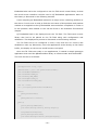
Configuring the ELM327 with AT Commands
By default the ELM327 should not need to be configured since it automatically
detects such things as the OBD-II protocol used on the connected vehicle and
hence nothing needs to be specified. However sometimes it is useful to modify
the behaviour of the ELM327 in a specific way that makes it work better with a
specific vehicle. We mentioned above that the ELM327 has an adaptive timing
feature that enables faster response times. These features are configured using
AT commands. The idea of an AT command comes from the modem era where
internal configuration of the modem was done by sending AT type commands to it.
The ELM327 supports a rich array of AT commands but I will only mention the
ones that proved most useful for Automon.
Adaptive Timing
The ELM327 supports 3 modes of timing:
•
No Adaptive Timing
•
Auto Adaptive Timing 1
•
Auto Adaptive Timing 2
By default, adaptive timing is turned on in the ELM327. Automon changes this to
Adaptive Timing 2 that is a little more excessive but still works. It results in faster
response times. This is important in functionality of Automon as it needs to be as
‘Real time’ as possible.
To turn on adaptive timing, you specify it by sending the command “ATAT1” or
“ATAT2” for the second version of it. The ELM327 interprets this command as a
configuration command since it begins with AT. The second AT is simply an
abbreviation for adaptive timing.
Headers On
Normally there is no need to view any header details but during the course of the
project I did encounter a time when I needed to view header information in order
to identify where diagnostic codes were coming from.
- 27 -
On the simulator I purchased that is discussed later below, it simulated sub
systems such as transmission unit and an ABS unit. I did not want to see
diagnostic codes from these so I had to filter them out, but how?
On a request for DTCs by sending a mode 3 command to the ELM327, it
responds with a list of all DTCs from all sub systems. In order to filter out DTCs I
required, I needed to turn on headers in order to view the sender or source
addresses (SA). Turning this on, it could clearly be seen the 3 OBD-II messages
with the 3 payload packets encapsulated in the header. It was only a matter of
identifying what payload I needed using the source address field of the header.
Header information can easily be returned by the ELM327 by simply turning
header information on by sending a “ATH1” command to the IC.
Other Useful AT Commands:
The following are other useful AT commands that are used by Automon:
•
ATDP - Describe current OBD-II protocol
•
ATRV - Read current battery voltage
•
ATEO - Turn echoing of commands off (Commands sent back on reply)
•
ATZ
•
ATWS - Warm restart of ELM327
- Cold reboot of ELM327
Cross Compiling and Toolchains
The TS-7390 is an ARM powered computer so application binaries that are
compiled for an AMD/Intel x86 based CPU are not compatible with the ARM
computer. This is the case since the ARM CPU instruction set is radically different
than that of our standard x86 based CPU. Both CPUs have different architectures.
For this reason, an ARM based compiler is required in order to compile our
binaries. In this project, not only did I have to cross compile my application, I
also had to cross compile the QT framework so as my application has the
necessary binaries on the board.
In theory it is possible to push the sources of QT and my application onto the
TS-7390 and compile using the onboard native GCC/G++ compiler that comes
with Debian Etch’s installation. However, in practice it is extremely infeasible.
First off, the processing power of the ARM CPU is only 200 MHz and obviously just
- 28 -
a single core. Secondly, the amount of storage space on the flash memory and
the amount of SD-RAM is extremely low. It would not be unusual to see the
compilation fail due to memory resources being exhausted. Compiling QT
Embedded (The C++ framework used in this project) on my desktop dual core
AMD processor took 3 hours. On a single core P4 in college, it took 6 hours. It
would have taken days on the ARM PC if it even got to the end without failing due
to lack of resources.
For this reason, another solution is available, a technique called cross
compiling. Before we will discuss cross compiling, the notion of a target and host
machine need to be defined.
Target and Host Machines
A target machine is the machine in which you want your application compiled for.
In this project’s case, it is the TS-7390.
The host machine is the development machine where development and cross
compilation of the application is performed. This would normally be a regular
desktop Intel/AMD x86 based CPU. The reason for this is the high availability of
cheap resources such as processing power and RAM. In my case, the host
machine was an Asus A6 AMD dual core processor with 1024MB RAM and 100GB
hard disk space.
Cross Compiling
Cross compiling is the term given to the procedure of compiling an application for
one processor architecture on another. Usually the application development and
cross compilation is done on the same development machine. Once the
compilation is done, the binary can be deployed or pushed onto the target
machine where it can be successfully understood. In my case, the binary would
be an ARM based one that would only be executable on an ARM based machine.
Cross compiling is a complicated process and getting the development
environment up can cause a lot of headaches. In order to cross compile, a special
compiler suite known as a toolchain is required.
Toolchains
A compiler alone such as gcc
[19]
is not enough in order to compile an application.
As well as the compiler, a linker and an assembler are also required. These all
have to be host binaries, in our case x86 binaries that output an ARM based
binary after the final linking stages.
- 29 -
As well as these tools (known as binutils on GNU Linux), specific libraries such
as the C library are also required as to have the required symbols available during
the compilation process. This entire suite of tools and libraries is known as a tool
chain. It has everything you require in order to successfully compile a target
based binary on a host development machine.
Building your own
toolchain is a complicated process mainly due to
incompatibilities between dependencies such as the glibc library and the gcc
versions. Getting the correct combination of the necessary binutils and libraries is
an art that is very difficult to develop. Most of the time, at least for ARM based
toolchains, special patches need to be applied to the sources. In order to build a
toolchain you must bootstrap. This means using the GNU C compiler, gcc to
compile itself as a C++ compiler, g++. Most people today don’t bother with this
complicated process and just download ready made binary versions available on
many sites.
I used the toolchain that came as part of the development package of my TS7390. Though it is an older version of the gcc/g++ compiler, it had very little
problems compiling the latest QT sources.
The actual procedures I used to cross compile are discussed on my project
blog.
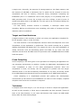
ECU Simulation Tools
Development of Automon required constant communication with an ECU in order
to perform testing of changes or newly added features. I did come across a
software based solution that emulated the actual ELM327 with ECU type
responses but this was not very helpful in that, the supported features were very
limited and timing wasn’t realistic as it would be on a real vehicle. The software
was called ECUEmu and was developed using Delphi and runs on Windows only.
The idea is to place it on a PC and connect it or associated it with a specific COM
or serial port. Then to that machine, you connect a null modem cable to the serial
port and connect it to another machine where your software would be running. A
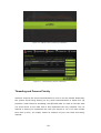
screen shot of the application is shown in figure 3.12 on the following page. While
it was a bit helpful and free, I did use it for a while but eventually I required a
more practical solution.
- 30 -
Figure 3.12 – The ELM327 Emulator Software
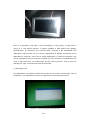
I done some more research and directed it more towards a physical solution.
There were not too many solutions out there but I did come across the perfect
one. Özen Elektronik is a Turkish company that develops ECU simulation chips for
all the OBD-II protocols including KWP2000, ISO9141-2. They develop their own
PCB boards that include a diagnostic connector (DLC) along with variable resisters
that change the value of sensors such as engine RPM, vehicle speed etc. The
prices are also very reasonable being just under 100 euro. Shipping only took a
day as well. A photo of the KWP2000 ECU simulator that I ordered, the mOByDic
1100 is shown in figure 3.13.
Figure 3.13 – The KWP2000 EOBD ECU Simulator in the development of Automon
- 31 -
The mOByDic 1100 is powered by the OE91C1010 chip providing a wide
variety of features. It simulates 3 ECU’s, the ECM, TCM and ABS systems. It
supports the following features:
•
Fixed PIDs such as Fuel System Status, Engine load etc.
•
Variable PIDs using variable resisters for PIDs such as engine RPM, coolant
temperature, vehicle speed etc.
•
Freeze Frame data on mode 2 for Engine Coolant Temperature, RPM and
vehicle speed.
•
6 Diagnostic Trouble Codes, all of different types (Powertrain, Network
etc)
•
Onboard Malfunction Indicator Lamp (MIL) or engine check light and push
button to simulate engine malfunction setting this light on and setting
DTCs
•
Turning off of MIL and clearing of DTCs using a mode 4 request
•
Pending DTCs support in mode 7
•
Vehicle Identification ID (VIN) in mode 9
•
Switch between fast OBD-II initialization mode and slow initialization mode.
Using these features, it was possible to develop all the Automon requirements
without the need to use any vehicle. The simulator behaves exactly how an ECU
would with realistic initialisation and communication timings.
Existing Solutions and Potential users
An important part to any project that involves a product being developed for the
general public is ensuring that adequate market research is done so that that
market isn’t saturated with existing products or if even customers will purchase
the product.
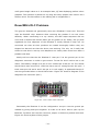
It took some time to come across a similar product to Automon. As a matter of
fact, it was in forums of the Scantool.net that one of the developers Vitaliy
pointed me towards another product. The product is called DashDAQ
[20]
and has
similar functionality to Automon. However, the screen is much smaller, being just
4 inches. Automon is almost double as big, being 7” diagonally wide. DashDAQ
does provide impressive functionality such as real time logging and graphing of
data changes, more detailed performance details of the vehicle, fuel economy and
- 32 -
much more. It even has an option of including a GPS module with the necessary
maps. Clearly, since this is just a final year project, Automon could not implement
such features or compete but it does have a lot of potential to fill these gaps.
The DashDAQ does sell for quite a cheap price, retailing at just $549 USD but this
is probably mainly to do with the size of the device. It may not be practical to use
at that size.
Besides this product however, not many other solutions exist. Most are just
software based solutions that would run on a regular laptop. The embedded
system design of Automon and DashDAQ improve on this greatly.
Seeing what products out there was only one part of the market research. It is
important to also ensure that there is actually a market there to purchase the
product. Due to the time constraints associated with a final year project, actually
doing proper market research such as surveys was not possible. Instead I made
my own justifications why this product would sell. These are as follows.
•
Engine Performance Tuners: These people require real time display of
information of what is happening in the engine during a trip around a track.
It is not practical having a laptop in the vehicle, especially if there is
nobody accompanying the driver. A further pointer on this is the fact that
laptops contain moving parts. When a vehicle is going at high speed
around bends etc, a laptop with a spinning drive may result in hardware
damage. The solid state nature of the TS-7390 is immune to this problem.
•
Mechanics and Auto Technicians: Being able to easily move a device
from car to car for the checking of fault codes and resetting of check lights
on the dash is useful. It is true that hand held diagnostic readers can
achieve this, but most of them do not give a detailed human readable
description of what is wrong.
•
Automotive Enthusiasts: People who take pride in their cars often like
to have fancy devices such as splashy DVD players etc on their dash to
impress people. Some people spend thousands of Euro just installing
speaker systems. Automon looks very impressive and attractive sitting on
the dashboard and is bound to get people’s attention.
•
The Regular Driver: Not forgetting the regular driver who may simply
feel comfortable knowing a device is there to check a problem if it ever
was to occur.
- 33 -
Chapter 4
System Design
Now that we have discussed all the background reading that this project relates
to, it is time to layout the design of Automon.
In semester one, the requirements were defined. Unfortunately, a re-scoping
of the project was done as it was not possible to implement all. So below is listed
all the features that this project will include:
•
Real time monitoring of vehicle sensors
•
Rules concept for checking state of sensors
•
Digital Dashboard
•
Acceleration Test
•
Read Diagnostic Trouble Codes (DTCs)
•
Clear DTCs and turn off the MIL (engine check light) if on
•
Retrieval of car details such as OBD standard and Vehicle ID (VIN)
This section will discuss both the high and low level design. Automon’s software
was developed using QT and object oriented C++. This provided a lot of
reusability and makes extensibility possible.
While a lot of projects describe use cases to present how the requirements
map to a user’s actions, I decided that this project wouldn’t benefit from them.
Use of the system is evident using the user manual that has been submitted as a
separate document. However, due to the object oriented design of Automon,
class diagrams and their interactions will be discussed later in this chapter.
- 34 -
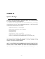
High Level Architecture Design
Automon contains 3 main components:
•
The Automon Software
•
The TS-7390 Hardware with Embedded Linux
•
The ELM327 IC
Figure 4.1 illustrates how these physical entities connect together while figure 4.2
gives a software based high level architecture.
Figure 4.1 – How Automon Connects to Various Components
As can be seen here, the ELM327 acts as a bridge between the vehicle’s
diagnostic connector and the TS-7390 hardware. As discussed in the previous
chapter, the ELM327 or ElmScan 5 in our case looks after all low level OBD-II
signalling for us.
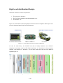
Figure 4.2 – High Level Software Architecture
- 35 -
The previous page shows a high level software architecture of Automon. The
software begins at the 3rd level from the bottom, embedded Linux. The Linux
distribution that comes with the TS-7390 is Debian Etch. On top of this we have
the standard C libraries and then the QT Embedded Library.
QT Embedded is configured to run on Embedded Linux. You will notice in the
figure, that there is no sign of any X11 windowing system or anything. This is
because QT Embedded is configured to use the Linux frame buffer device. This
allows applications that use QT Embedded to render their GUI’s directly to the
frame buffer by passing the need for any windowing system. As a matter of fact,
QT Embedded can support its own windowing system. Automon requires the use
of serial communication and development of a library has already been done for
QT, QExtSerialPort as shown in the figure.
On top of QT Embedded, we have our Automon application software. I decided
to break this software up into two main components, a kernel system that will do
all the various tasks such as scheduling sensor reading, polling, reading
diagnostic codes etc while the higher level layer, the GUI will look after the logic
in how the user can use these functions.
Modular Decomposition
Before starting coding, it was important to break up the project into sub systems
in order to iteratively build the system. Automon can be broken up into many
areas. We will discuss these in more detail.
•
Serial Communication System and Sensor Monitoring
•
Diagnostics
•
GUI and Logic
Serial Communication System and Sensor Monitoring
One
of
the
most
crucial
parts
of
the
Automon
software
is
the
serial
communication system. Almost all actions that Automon executes will involve
some serial I/O communication with the ELM327 chip in order to gather
information from the ECU or instruct it to perform a task.
- 36 -
The serial communication is all handled using the SerialHelper class. It can
handle both once off commands to the ECU or be set up in such a way to
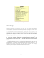
automatically query several sensors periodically.
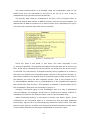
The primary base class for commands to the ECU is the Command class. It
constructs objects that contain an OBD-II request. From the previous chapter, we
learned that an OBD-II command is a mode number plus a parameter ID. Figure
4.3 shows the command class with various methods.
Figure 4.3 – Command Class
There are quite a few fields in this class. The most important is the
m_command attribute. This specifies the OBD-II command that will be sent to the
ECU. If this was a command the vehicle’s speed, we would have the string “010D”
in this field. For convenience, an English meaning string is passed to it as well so
that users can identify such commands easily. We saw in the previous chapter, in
the section related to the ELM327 that an expected bytes number can be sent so
the ELM327 can return the ECU response quicker. That is the purpose of the
m_expectedBytes attribute. The m_bufferResponse is the hexadecimal response
that comes back from the ECU. This attribute is attribute is automatically set by
the SerialHelper class when the command is sent to it.
Sending a Command object to the SerialHelper class is a way of performing
once off readings. For example, things such as checking the number of DTCs or
requesting the vehicle’s ID (VIN) are some uses for the Command class.
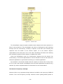
When monitoring sensors, a new object is formed, the Sensor object. It has
similarities to the Command class so it inherits from this and adds additional
functionality. Figure 4.4 on the following page shows the Sensor class. The class
acts as a base class for a sensor such as EngineCoolantTemperature sensor class.
These classes describe how the bytes manipulated to derive the result.
- 37 -
Figure 4.4 – Sensor Class
The SerialHelper object accepts multiple Sensor objects and stores pointers to
them in an internal list. The SerialHelper can then be configured to start iterating
through the list continuously, sending a request to the ECU and inserting the
response into the buffer of the Sensor object. It is the Sensor object’s
responsibility from that point on to look after formatting this data and emitting
the necessary signals to other objects to update their state.
Since the SerialHelper must run continuously iterating over the Sensor list
continuously, it has to be implemented in its own thread or else we will cause the
Automon application to get blocked resulting in a useless application.
QT provides a convenient thread class for objects to inherit from if they want
to run in their own thread. SerialHelper does this and implements a special run()
method. QT and its implementation are discussed in more detail below.
The Sensor Frequency Concept
Automon has a very important design element included in the querying of OBD-II
sensors. This is the frequency concept. Automon uses a polling based system in
- 38 -
order to query the ECU for data. This is also true with the monitoring of a list of
sensors. Each sensor must send a command to the ECU and wait on a response
before moving to the next sensor. The speed at which the ECU responds is
variable but generally only a few samples of a single sensor can be retrieved in a
second. The more sensors that are added to the SerialHelper for monitoring, the
less frequent each sensor will get updated due to the limitation of OBD-II. CAN
protocols are however faster and it is possible to obtain up to 20 samples per
second dramatically improving how frequent the sensors get updating updated.
The design of Automon has implemented the notation of a sensor frequency.
Some sensors do not need to be updated as often as other more changeable ones.
For example, it does not make sense to check the engine coolant temperature
very often as this does not change rapidly. It may go up a degree every 10
seconds. This is not true however, for more frequently changing sensors such as
the engine RPM. This sensor could change every 10th of a second so it should get
updated as much as possible.
Each sensor object contains an m_maxFrequency attribute. This attribute is an
integer value that determines within how many cycles of the sensor list, will it get
a chance to communicate with the ECU. Every time the SerialHelper goes through
the sensor list, it checks the m_currentFrequency attribute to check if it is time
for
the
current
sensor
to
get
access
to
the
ECU.
If
it
is
and
the
m_currentFrequency is equal to the m_maxFrequency, it updates its buffer after
sending the command to the ECU and then resets its current frequency back to 0
again so it won’t get access to the ECU until the m_currentFrequency reaches the
m_maxFrequency attribute again. Every time the list is cycled, each sensor’s
m_currentFrequency attribute gets incremented so in a number of cycles it will
equal the m_maxFrequency attribute and get access to the ECU. So for example,
we might set the m_maxFrequency of the engine coolant temperature to 20,
while we set the m_maxFrequency attribute of the engine RPM to 1. If these are
the only two sensors added to the SerialHelper, the engine RPM will get updated
20 times before the engine coolant temperature gets updated.
The figure on the following page shows the SerialHelper class. All methods on this
should make sense now. The addActiveSensor() is the method in which you can
add
a
sensor
to
the
sensor
list
for
the
monitoring
functionality.
The
sendCommand() method is the one that accepts a standard Command object that
does a once off query to the ECU.
- 39 -
Figure 4.5 – Serial Helper class
Diagnostics
The diagnostics sub system of Automon deals with such things as diagnostic
trouble codes (DTCs), loading fault codes database, and resetting the malfunction
indicator lamp (MIL) etc.
It handles all this using the DTCHelper class. This class is responsible for the
following:
•
Checking for DTCs on system start up and generating DTC objects
•
Loading fault code database to provide human readable explanation
•
Clearing the DTC codes and resetting the MIL
To do this functionality, the DTCHelper requires access to the SerialHelper object
in order to send commands to the ECU. This is the reason it takes a SerialHelper
pointer in its constructor.
The class diagram of the DTCHelper class is shown in figure 4.6. All methods
and attributes are self explanatory. These are all detailed in the comments of the
code implementation.
- 40 -
Figure 4.6 – DTC Helper class
GUI and Logic
Automon separates the GUI from the main low level serial I/O and ECU
communication components. It does this by creating a package or a name space
in which all these low level components and classes exist. This is known as the
AutomonKernel. The GUI is not part of this package and it communicates with the
AutomonKernel interface in order to perform all low level tasks such as loading
DTCs, sending serial I/O commands etc.
The AutomonKernel name space contains several objects that all work together
to provide the necessary functionality. The AutomonKernel’s interface is the
Automon class and this can be seen in the class diagrams that come in a later
section.
The GUI is developed on top of this kernel and implements the main logic for
the application. For example, the acceleration test uses sensor monitoring in the
kernel but the higher level logic such as starting counters and stopping
monitoring when a speed is reached is all handled by the GUI.
- 41 -
Human Computer Interaction (HCI) Design
Automon runs on the TS-7390 which includes a 7 inch touch screen display for
interactions. Development of an application for a touch screen is a lot different
than that of a conventional desktop application that has much larger displays and
a mouse for more accurate control.
For a touch screen interface, it is important to have large buttons that are easy
to press. We don’t know what size the user’s fingers will be and since multiple
users, everyone will be different. It is important then to create a button that will
work conveniently with the majority of users. Figure 4.7 illustrates the look and
size of the button’s used in Automon.
Figure 4.7 – The Standard Automon Button
The menu of Automon also includes large buttons on top that are easy to press.
These buttons are illustrated in the following figure.
Figure 4.8 – Automon’s Menu Buttons
As well as having buttons large enough so as it is easy to tap on them, it is also
important to keep the number of taps in order to achieve a goal to a minimum.
The GUI was designed in such a way that it is most straight forward to achieve a
task. For example, to start an acceleration test, it only takes 2 taps - once to
view the widget using the menu button and another to start it. Automon looks
after the rest for you.
Overall the user experience is satisfactory but there are areas where things
could be better. For example, the combo boxes are difficult to work with in a
touch screen environment. First of all they are a bit small and secondly to scroll
down them is rather difficult. However improvements could not be made for this
as screen space was really limited. In a real commercial product this would have
to be sorted first before release of the product. But since this is a final year
project and time is a big constraint, I decided to let the GUI the way it is.
- 42 -
Class Diagrams
The following class diagrams have been broken up due to their size.
The class diagrams that follow are:
•
AutomonKernel
This is the biggest class diagram showing all the various objects of
Automon and how they interact together. The Automon class is an
interface
•
class
that
the
GUI
uses
in
order
to
perform
tasks.
Main GUI
On top of the kernel sits the main GUI. The GUI application is called
AutomonApp. The various widgets that form the application are also
shown but the details of these are left to the following pages.
Unfortunately it is not practical to show all detail in the class diagrams. Further
more, QT related classes have being ignored since these relationships are obvious.
The views in the Automon applications have being developed as individual
widgets. The main GUI widget contains these widgets and the menu bar on top of
Automon changes these widgets. The menu bar, the MenuWidget is made up
several child widgets, MenuItem which are essentially sub classes of the
QPushButton class. Figure 4.9 shows a screen shot of the application with each
widget type labelled.
Figure 4.9 – The Automon GUI Elements
- 43 -
The AutomonKernel Package
Figure 4.10 – The GUI Class Diagram
- 44 -
The Main GUI Relationships
Figure 4.11 – The GUI Class Diagram
- 45 -
Chapter 5
Implementation and Deployment
Unlike other final year projects, this one involved the development of both a
software and hardware aspect. The TS-7390 was the device that the software
was hosted on but it was not a simple matter of just copying and pasting it on the
device. This section will describe the development environment that had to be set
up in order to work with the TS-7390 and what configuration was required to the
TS-7390 in order to successfully get it up and running. The programming tool of
choice was QT Embedded so this needed to be fully installed and working on the
TS-7390.
It is not possible to include everything in this section but any details of how I
accomplished such things as cross compiling libraries, configuring the touch
screen and so on can be found on my project blog at:
http://automon.donaloconnor.net
Choice of Programming and Tools
In semester one we done a lot of research into our project and investigated what
tools would be suitable in order to successfully implement it. The following
discusses the language of choice and what tools were required to set up.
C++ and QT for Embedded Linux
QT for Embedded Linux was used for this project. QT for Embedded Linux is very
similar to the regular QT version. The differences are its performance, small foot
print design and the support for its own windowing system. This means that it
- 46 -
can write directly to the Linux frame buffer device removing the need for any X11
window manager.
The QT framework was originally written for C++ but now has several bindings
to other languages. QT for Embedded Linux however has to use C++ but this
suits due to C++’s efficiency.
Trolltech, the makers of QT do not release binary versions of their QT
Embedded solution. This makes sense as it is impossible to have cross compiled
binaries ready for every platform. Instead they provide the sources. In order to
get QT Embedded set up on the TS-7390, I had to cross compile it using an ARM
toolchain. This toolchain came with the TS-7390’s development kit. For
development of the application on my machine, I also had to compile QT
Embedded for the x86 architecture so I could run it on my Xubuntu machine. It
was also necessary to compile the normal QT for X11 since this was required to
compile the virtual frame buffer device that comes with QT Embedded called qvfb.
The Virtual Frame Buffer Device - qvfb
The virtual frame buffer allows you to run applications developed for QT
Embedded on your development machine rendering the output to this virtual
frame buffer application. This application, qvfb can be configured to what ever
resolution your target device is and what color depth it supports. This will then
give you the output of exactly how it would look on the hardware device. This
proved to be an extremly useful application since it did not require me to use the
TS-7390 for the most part.
QT Creator
During the research phase in semester one I investigated what integrated
development environment tools (IDEs) would be suitable. At the time there was
talks of Trolltech releasing their own IDE codenamed Greenhouse. After a few
months they released this. It is called QT Creator and is a full featured IDE with
code completion and debugging facilities built in. This was the tool that I used in
order to develop my applications. It proved to be very useful. It also had the full
API built in to its documentation. QT’s documentation is second to none.
- 47 -
QExtSerialPort
Automon requires communication via the serial interface. This could have been
done in C or C++ but would have required a lot of work and made it dependent
on
a
specific
platform.
However,
after
further
research
I
came
across
QExtSerialPort, a cross platform wrapper API for serial communication built using
QT. This library had to be cross compiled as well. The library works very well and
makes communication with serial devices really easy and productive.
mOByDic 1100 ECU Simulator
This device has already been mentioned in the background research chapter.
However it deserves to be reminded of here since it was an extremely helpful tool.
It probably wouldn’t have been possible to develop Automon fully without the use
of this.
Development Environment
Before any development of Automon began, the development environment was
important to set up properly. First of all I had to install Linux on my development
machine since it is not possible to build QT Embedded in any other operating
system. I installed Xubuntu since this flavour of Ubuntu is very quick and does
not hog resources.
In my home directory I created a project folder that included everything
required, from sources of QT Embedded to libraries such as QExtSerialPort and
TsLib. It was important to keep everything together so backup was easy. Here is
the directory structure of my project:
/home/donal/project
•
automonproject/
o
src/
o
build/
o
debug/
•
downloads/
•
sysapps/
•
o
device
o
host
o
qextserialport
libs/
- 48 -
The tool chain for cross compiling was at:
/usr/local/opt/crosstool/arm-linux/bin
The compiled versions of QT were located in:
QT 4.5:
/usr/local/qt4/
QT Embedded 4.5:
/usr/local/qte4.5/
ARM QT Embedded 4.5:
/usr/local/Trolltech/QtEmbedded-4.5.0-arm/
In order to set up the environment to cross compile, the following was required to
be entered in the bash shell:
$ export PATH=$PATH:/usr/local/Trolltech/QtEmbedded-4.5.0-arm/
$ export LD_LIBRARY_PATH=$LD_LIBRARY_PATH:~/project/libs/qextserialport/build/
$ cd ~/project/automonproject/
$ qmake
$ make
The specifications of my development machine were:
CPU:
AMD Turion TL50
RAM:
1024MB
HDD:
100GB
Project Iterations
Development of Automon was broken up into iterations. The following discusses
the approaches taken in these iterations. It is not possible to include all detail
here, so I will just give an overview. The main details can be found on my project
blog/diary viewable at: http://automon.donaloconnor.net
Iteration One: Prototype on TS-7390
This was on of the most important iterations. It was important to get a working
prototype on the TS-7390 as soon as possible to ensure that work done in further
iterations would successfully run on the TS-7390. This iteration involved cross
compiling QT Embedded for the TS-7390 ARM architecture. The compilation of QT
- 49 -
Embedded also had to be configured to use the Tslib touch screen library so that
the touch screen interface could be used in QT Embedded applications. More on
this library is discussed in the following sections.
Cross compiling QT Embedded resulted in a major colour rendering problem on
the device. It took over a week to find the root cause of this problem and patches
needed to be applied to the QT Embedded sources before compilation in order to
fix the problem. More details on this can be found in the Problems Encountered
chapter.
QT Embedded had to be deployed onto the TS-7390. The Tslib touch screen
library also had to be placed on the TS-7390 along with configuration and
calibration. This deployment process is discussed in the following sections.
The TS-7390 had to be configured in such a way that the X11 service was
disabled on start up. Otherwise, since the applications write directly to the frame
buffer, the display on the screen would become corrupted.
Once the TS-7390 was ready to run applications, I created a simple prototype
application that used the QExtSerialPort library to communicate with the ELM327.
The code for this is as follows:
int main(int argc, char *argv[])
{
QCoreApplication a(argc, argv);
QextSerialPort * port = new QextSerialPort("COM8");
port->setBaudRate(BAUD9600);
port->setDataBits(DATA_8);
port->setParity(PAR_NONE);
port->setStopBits(STOP_1);
port->setFlowControl(FLOW_OFF);
bool res = false;
res = port->open(QextSerialPort::ReadWrite);
if(res)
qDebug("Connected\n");
else
qDebug("Failed to connect");
while(1)
{
QString message("ATE0\x0D");
port->write(message.toAscii(),message.length());
SleeperThread::msleep(500);
QString message2("010C\x0D");
port->write(message2.toAscii(),message2.length());
- 50 -
SleeperThread::msleep(500);
char buff[1024];
int bytesToRead = port->bytesAvailable();
int result = (int)port->read(buff,bytesToRead);
buff[result] = '\0';
char byte1[3];
char byte2[3];
byte1[0] = buff[11];
byte1[1] = buff[12];
byte1[2] = '\0';
byte2[0] = buff[14];
byte2[1] = buff[15];
byte2[2] = '\0';
long int B1;
long int B2;
char * next;
B1 = strtol(byte1,&next,16);
B2 = strtol(byte2,&next,16);
cout << "Bytes: " << B1 << " " << B2 << "
RPM: " << ((B1*256)+B2)/4 << endl;
}
port->close();
return a.exec();
}
This is a console application that I created that continuously queried the ELM327
for the engine RPM. You can see that it writes a 010C\x0D command to the
ELM327. From chapter 3, we learned that a command contains both the mode
and the parameter ID. So here we see the mode is 01, since we want to read
current real time data and the PID is 0C since we want to request the engine RPM.
We also learned that the engine RPM returns 2 bytes and a formula is applied to it,
seen in the final cout of the program above. These two bytes that are returned
are ASCII strings so conversion using the strtol function is required. I then
outputted the RPM continuously. Obviously this method is only a prototype
method so things are hard coded. Another problem is I set a sleep or delay in the
code after a write request to wait for the input buffer to fill from the ELM327 and
ECU responses. The output of this code can be seen in figure 5.1.
- 51 -
Figure 5.1 – The First Console Prototype on the TS-7390
Once it successfully read after a bit of tweaking to the timing, it was time to
move to a GUI based solution. I simply updated a GUI based LCD Widget,
QLCDNumber to represent the vehicles RPM. Running a QT Embedded GUI
application requires the use of a server application to handle windowing of the
applications. However, since only a single application is used for Automon, this
server application was not required. Instead you can choose to run applications in
such a way that they use themselves as the server process. This is done by
passing the ‘qws’ command line switch as follows:
$ ./automonapp –qws
The application successfully loaded up and the touch screen worked after a bit of
calibration. This calibration process is explained in the following sections.
Figure 5.2 – The GUI Prototype on the TS-7390
- 52 -
Iteration Two: The Automon Kernel
Iteration one was mainly concerned with getting the TS-7390 ready for the
Automon software. Iteration two was the iteration that was focused on getting
the main functionality of the Automon software developed.
My strategy of development was a bottom up approach where I first
implemented all the necessary functionality at a low level before developing any
GUI or business logic. This meant that I had to develop all the serial I/O related
communication with the ELM327 and provide all the necessary functionality that
made use of this serial I/O. This was the main purpose of this iteration. It is
impossible to detail all the parts of this iteration since it took over a month or two
solid of work. However, I will list the features that this iteration accomplished:
•
Sensor architecture where sensors can implement a Sensor base class and
re-implement their
own conversion formulas and allow the setting of a
update frequency that was explain in the previous chapter
•
Load sensors up in the SerialHelper class to start real time monitoring
•
Record sensor’s average and instantaneous update frequencies
•
Load DTC database and check if any present on ECU
•
Determine if the MIL is on or off and if on provide functionality to turn it
off and clear DTCs
•
Get the car’s battery voltage
•
Get the car’s OBD-II protocol name
•
Automatically check what sensors supported in car and disable sensors
that are not supported
•
A rule based system where rules can be created on sensors during a
monitoring session
The following sections detail some of the more complex problems that I
experienced during the implementation of this phase. They also provide a brief
summary of how the solutions were implemented.
Sensors Architecture
Every sensor on the vehicle has its own logic of how to convert the bytes returned
into a meaningful value. In the design chapter, I discussed how the sensor class
inherits from the command class since it is a type of command. However, I did
- 53 -
not discuss how sensors inherit from the sensor’s object and re implement the
conversion formula method.
The base Sensor class provides a virtual method called convertResult(). All sub
classes of sensor, such as the CoolantTempSensor class re-implement this
method. This method can access the returned data bytes in the m_returnedBytes
byte array. Based on this, it performs to necessary formula, returning the final
calculated
value.
Here
is
an
example
of
the
CoolantTempSensor’s
re-
implementation of convertResult().
double CoolantTempSensor::convertResult()
{
QList<int> bytes = Automon::getBytes(*this);
double value = (bytes[2]-40);
return value;
}
Note: The reason it reads from byte [2] is because the first two bytes are bytes
that the ECU always respond with detailing what command was sent. This is used
for confirmation that the resulted bytes are for the correct command.
This method is generally not called from outside the sensor object. It is done
internally when the buffer is set by the SerialHelper thread. If the result has
changed from the previous result of the sensor, it will emit a signal to notify
listeners of this sensor that a change has occurred. This may be a LCD number on
the GUI or simply a logger.
This is similar to the Observer Pattern, where multiple listener objects are
connected to an object that changes. This pattern is naturally implemented by QT
already with the use of its signal and slots
[21]
mechanism. Objects can implement
special methods called signals and slots. The signal of one object can be
connected to a slot of another so whenever that object emits it’s signal, the slots
connected will be called. Parameters can be sent from signals to slots as well and
in Automons case, the value of the sensor is emitted and all connected slots get
this value. This is a convenience mechanism where the listeners do not have to
go to the trouble of looking up the value manually using a getter method of the
sensor.
All sensors are stored internally within the kernel. In order to use them, they
are identified by using helper methods to locate their pointers. The following code
example demonstrates how two sensors: the engine RPM sensor and the vehicle
- 54 -
speed sensor can be added to the monitor. The last line then starts the monitor
where the ECU will be polled continuously for these sensor values.
if(automonApp.addActiveSensorByCommand("010C"))
{
automonApp.connectSensorToSlot(automonApp.getActiveSensorByCommand("010C"),lcdNumber1)
;
automonApp.setSensorFrequency(automonApp.getActiveSensorByCommand("010C"), 1);
}
else
qDebug() << "Command not supported by ECU";
if(automonApp.addActiveSensorByCommand("010C"))
{
automonApp.connectSensorToSlot(automonApp.getActiveSensorByCommand("010C"),lcdNumber1)
;
automonApp.setSensorFrequency(automonApp.getActiveSensorByCommand("010C"), 1);
}
else
qDebug() << "Command not supported by ECU";
automonApp.startMonitoring();
Rules System
One of the most useful functionalities of Automon is the rules based system. The
rules system allows a user to create a rule dynamically during run time where the
rules are based on various sensors and their states.
An example of a rule might be “EngineCoolantTemp < 60 AND Engine RPM >
4000”. When the engine coolant temperature goes below 60 and at the same
time the engine RPM is greater than 4000RPM, then this rule becomes satisfied.
When it becomes satisfied, it emits a signal to notify any listeners of the rule that
the rule conditions are met. On the main Automon application, the rule
description in the rules list table becomes highlighted when the rule becomes
satisfied to notify the user that its condition has been met.
This system is one of the more complex parts of Automon. The main reason
behind the complexity is the fact that C++ cannot execute dynamic run time code
where as other languages such as PHP and Javascript can with the eval method
where a string of code can be executed. This would have been very useful in C++
as we could create logic like “If < sensor1.value() > 4000 && sensor2.value() <
60” and execute it. However, since such a thing was not possible a lot of
investigation in to alternative solutions had to be figured out.
QT provides an extremely convenient module, the QtScript module. This
module allows you to execute ECMAScript (Javascript) during run time. This
allowed me to create a structure where rules could be added simply as follows.
- 55 -
Rule r1;
r1.setRuleName(“You
may
be
wearing
your
engine.
Reving
too
high
and
coolant
temperature too low”);
r1.setRule(“s010C > 4500 && s0105 < 60″);
r1.addSensor(automonApp.getActiveSensorByCommand(“010C”));
r1.addSensor(automonApp.getActiveSensorByCommand(“0105″));
QObject::connect(&r1,SIGNAL(sendAlert(QString)),&errorHandler,SLOT(errorslot(QString))
;
if (r1.activate())
qDebug() << “Rule Added”;
else
qDebug() << “Error Adding Rule”;
The AutomonKernel workings are hidden from the user behind the Automon
interface class. This class can be used to perform all the necessary functionality of
Automon. Here are a few examples of its use.
The string for this rule is “s010C > 4500 && s0105 < 60”. The reason behind
having the s before the numbers is that like most languages, variable names
cannot begin with a number. These act as variables in the script engine. These
variables are then assigned the sensor values every time the sensors emit a
signal. That is the reason why we must add the sensors to the rule, so that they
get connected to the sensor’s signals and listen for changes. Every time a change
occurs, the sXXXX variables get updated appropriately and then the rule in
general is evaluated. If the rule is satisfied, the rule emits the sendAlert() signal
where the listener of the rule (the error handler in this case) can get alerted that
the rule has become satisfied. A string is also passed identifying what rule caused
the alert.
Other parts of the AutomonKernel can be easily accessed using the Automon
interface class. For example, checking if the engine MIL is on is only a matter of
checking the Boolean that the Automon::checkMIL() method returns.
- 56 -
Iteration Three: The Graphical User Interface
When all functionality of Automon was implemented in previous iterations, it was
time to implement that GUI interface and the business logic of the application.
This iteration was complex enough but it didn’t take long as it was a repetitive
task. The GUI contains various parts:
•
The Start up Splash Screen
•
The Main GUI Frame including Menu bar and Status bar
•
The Monitoring Widget
•
The Digital Dashboard Widget
•
The Diagnostics Widget
•
The Acceleration Test Widget
•
The Car Details Widget
•
The Rule Editor Widget
The first task was to develop the main GUI frame including the splash screen
on start up. The splash screen was an important part of the GUI since it gives the
user an idea of what is happening on start up since the process can take up to 10
– 15 seconds. The main GUI frame implements the menu bar system and the
status bar. The other widgets are all children of the main GUI frame. They are
implemented within a StackedWidgets framework. This is like an invisible tab
system where only one widget can be seen at a time. The menu buttons are
responsible for changing the visible widget in the stack.
Each individual widget implements its own logic system. For example, the
Acceleration Test widget includes such things as timers. It looks after handling all
the logic related to starting the timer when the vehicle starts moving and
stopping it when vehicle reaches the specified destination speed. This is one of
the simpler widgets. The most advanced and complex one definitely had to be the
Monitoring widget since it involved the use of rules as well.
The following page includes 2 screen shots of what Automon looks like. Figure
5.3 shows the splash screen that is shown on the start up of Automon and figure
5.4 shows the Monitoring widget view.
- 57 -
Figure 5.3 – Splash screen on start up of Automon
Figure 5.4 – The Monitoring section of Automon
Threading and Process Priority
Automon requires the serial communication to occur in its own thread. Otherwise,
the system would hang waiting on any serial communication to finish first. QT
provides a useful class for threading, the QThread class. In order to use this class
you must derive a new class from it and implement the run() method. The run
method is where you implement the code you require to run in its own thread.
Once this is done, you simply create an instance of your new class and start()
method.
- 58 -
In Automon, the SerialThread class sub classes QThread and implements the
run() method for the continuous monitoring of sensors. Once off calls to the ECU
do not require to run in their own thread, so these are just handled using a
normal method. Every time Automon begins monitoring sensors, it simply starts
the SerialHelper thread. Within the run of this, it loops around a Sensor list array
and communicates with the ECU in order to update each of these sensors
continuously. The sensors then emit signals if their values change so listeners get
the updated values.
QT provides a method in which you can change how the threads are scheduled.
For example running some threads as often as possible is not required, while
others, notably the SerialHelper thread is a necessity. In order to change how
critical a thread is, QT provides the setPriority() method. Alternatively, the
priority can be passed to the start() method when the thread is started. The
following is a list of the different options or enumerated types available when
setting the thread priority.
•
QThread::IdlePriority
•
QThread::LowestPriority
•
QThread::LowPriority
•
QThread::NormalPriority
•
QThread::HighPriority
•
QThread::HighestPriority
•
QThread::TimeCriticalPriority
•
QThread::InheritPriority
If you choose a priority towards the start of the list, the thread will get scheduled
less often than that of the ones towards the end of the list excluding
InheritPriority. If no priority is specified, the InheritPriority is selected which is
generally just NormalPriority.
In
Automon,
I
decided
to
start
the
SerialHelper
thread
with
the
TimeCriticalPriority as it is essential that the serial communication gets access to
the CPU as often as possible.
Debian Etch is not a real-time operating system (RTOS). However, in later
versions of the Linux kernel it supplies the nice command. This command can be
used to start a process with a user specified priority. This will affect how the Linux
kernel process scheduling system will operate on the process. Since the Automon
application is the only main user application that runs on the TS-7390, I decided
- 59 -
that it would be best to start it with a high priority. This decision was made after I
noticed that there was random hangs and missing of returned serial bytes from
the ELM327. In order to start the Automon application using a high priority, I
used the following command from bash:
$ nice –n -20 ./automon
This starts the Automon application with the highest priority (-20). More details
on the problem that I was experiencing with loss of serial characters is discussed
in the Problems Encountered chapter.
Tslib and Configuring the Touch screen
Users interface with the TS-7390 using the touch screen display. Debian Etch
already comes with the necessary driver for it, located at /dev/input/event0.
However in order to use this driver, a library or API must be used. QT Embedded
does not include any touch screen library but can be compiled with support for an
existing touch screen library.
After some research I came across Tslib – an abstraction layer for touch screen
panel events. It was created by Russell King, one of the main guys involved with
ARM Linux distributions. It allows a lot of configuration of how the touch screen
behaves with different pressures on the screen etc.
To get Tslib running on the TS-7390 I had to cross compile it using my tool
chain. Details of this can be found on my blog. Once it is cross compiled, I had to
link to it when compiling QT Embedded. This was only a matter of specifying the
include paths for libraries and include header files when compiling QT Embedded.
The QT Embedded configure script also had to be passed the –qt-mouse-tslib
option. The full line is as follows.
echo yes | ./configure -embedded arm -xplatform qws/linux-arm-g++ -no-qvfb depths all -qt-mouse-tslib -qt-kbd-usb -I /usr/local/arm/tslib/include -L
/usr/local/arm/tslib/lib
This configuration configures the QT Embedded build to include support for Tslib.
Instead of a mouse controlling the pointer, it will now be the responsibility of the
touch screen.
- 60 -
This was only part of the procedure however. In order to get Tslib working fully
on the TS-7390, it had to be configured. Configuration of Tslib is all done in the
ts.conf file. This is what my file looked like:
module_raw input
module pthres pmin=1
module variance delta=30
module dejitter delta=100
module linear
The next step is to calibrate Tslib so it can provide accurate pointing based on
your finger position. This is done using the ts_calibrate application that comes in
the bin folder of the Tslib installation. When you run this, you are prompted to
tap on cross hairs in several locations in the screen. This will then generate a
calibration file in a location specified by the TSLIB_CALIBFILE environment
variable listed below.
Before QT Embedded applications can be started certain environment variables
have to be set up. I placed these in the /root/.bashrc script originally so every
time the TS-7390 started up, the necessary variables would be in place. However
these changes were moved to the rclocal file as later discussed. The environment
variables are set up using the export command on Debian. The following shows
these exports. The path in which Tslib is installed on the TS-7390 is /etc/linuxarm/
export TSLIB_TSEVENTTYPE=H3600
export TSLIB_CONSOLEDEVICE=none
export TSLIB_FBDEVICE=/dev/fb0
export TSLIB_TSDEVICE=/dev/input/event0
export TSLIB_CALIBFILE=/etc/pointercal
export TSLIB_CONFFILE=/usr/local/linux-arm/etc/ts.conf
export TSLIB_PLUGINDIR=/usr/local/linux-arm/lib/ts
From the environment variables, it can be seen that the touch screen device is
/dev/input/event0. This device is created automatically on start up when the
touch screen driver is loaded.
- 61 -
Deployment of QT Embedded on TS-7390
Cross compiling QT Embedded was only one part of the puzzle. Next it has to be
moved onto the TS-7390. When the TS-7390 is started in the normal mode (not
fast boot), SSH, FTP and telnet services start.
There are multiple ways in which I could deploy my applications onto the board.
Since I was using a SD-Card during development, I could easily place this in my
card reader and copy on the necessary data. However, this would not work when
I move to the onboard NAND flash. Instead I decided to push the library onto the
board using Secure Copy with SSH. This is a much better solution over FTP since
it allows the sending of directories. The FTP server installed on the TS-7390
would only support the sending of individual files and did not allow recursive
sending of directories.
The command for secure copy is scp. It takes a user name, an IP or hostname
address and the necessary files to send including the destination file system
location. The recursive option is done using the –r switch. It will then recursively
travel down directories copying it onto the destination.
The SSH service was only set up to use the eclipse login on the TS-7390 so
anything I copied over needed to be in this name. Due to this I had to copy the
QT library to the eclipse’s home directory first using the following commands:
$
$
$
$
$
$
$
cd /usr/local/Trolltech/
scp –r QtEmbedded-4.5.0-arm/ [email protected]:/home/eclipse
telnet 192.168.0.50
user:root
cd /home/eclipse
mkdir /usr/local/Trolltech
cp –r QtEmbedded-4.5.0-arm /usr/local/Trolltech/
These commands from my development PC successfully copied the QT Embedded
library to the correct location on the target machine, the TS-7390. Unfortunately
there was more required. QT Embedded requires the libstdc++.so.5 library file. I
downloaded
this
from
the
internet
and
copied
it
on
the
board
at
/usr/local/Trolltech/QtEmbedded-4.5.0/lib using a similar method to above. Once
this is done, a few environment variables have to be set up before QT Embedded
applications can run. These are as follows.
$export LD_LIBRARY_PATH=$LD_LIBRARY_PATH:/usr/local/linuxarm/lib/:/usr/local/lib:/usr/local/Trolltech/QtEmbedded-4.4.3arm/lib/
- 62 -
$export QWS_MOUSE_PROTO = Tslib
The QWS_MOUSE_PROTO environment variable simply tells QT to use Tslib for
mouse events. Similar to the Tslib environment variables, these were added to
the /root/.bashrc script so on start up they would automatically be set.
Starting Automon Automatically from Bootup
During development I used the JTAG connector to communicate with the TS-7390
on start up so it would boot out of fast boot mode into normal mode. Then on
start up of the telnet service, I’d run Automon from command line over a telnet
session.
Clearly this method of execution is not suitable to a customer especially in a
vehicle! So to fix this, I first had to get the TS-7390 booting automatically into
normal boot mode and not the fast boot mode that occurs by default. The reason
nothing can be done on the fast boot mode is that it loads up a read only file
system and QT Embedded requires write operations for caching reasons. To get
the TS-7390 booting into normal mode by default I executed the following
commands from the Linux console on start up in fast boot mode:
$ rm linuxrc; ln –sf /linuxrc-sdroot /linuxrc; save
The first script that Linux executes on start up is the linuxrc script. The TS-7390
comes with different versions of this and uses a symbolic link to point to what
ever one is to be used. This command removes the symbolic link and creates a
new one to the linuxrc-sdroot script, the one that boots into the SD-Card with a
normal start up.
Once this is done, the Automon application has to be started on start up. To do
this I modified the /etc/rc.local script. This script is the last script that is executed
in run level 3. The fact that we are at run level 3 means that no users will get
logged in so our /root/.bashrc script will not get executed. For this reason I had
to include the environment variables in the /etc/rc.local script before executing
the Automon application. The nice command was used to start the application so
it stats with a high process priority. This configuration resulted in Automon
starting automatically when the device boots up so there was no longer need for
any cables to be connected to the device and the JTAG connector did not need to
be used anymore.
- 63 -
Chapter 6
Evaluation and Testing
Testing is an important part of any project whether it a small final year project or
a huge commercial system. Testing is an activity that can go on forever so it is
important to test the areas that are most important and the areas that are most
likely to reveal bugs. Like any project, exhaustive testing is not possible. Testing
is a highly strategic activity and different methodologies are used. This chapter
outlines the methodology I took for testing Automon and gives an overview of the
various results and problems discovered.
Testing Methodology
This project was developed using an iterative approach. However performing
testing during these iterations was limited due to the time constraints associated
with a final year project. Instead I did exploratory testing
[22]
without any
documentation and fixed any problems I discovered on the fly. The main
documented testing was done at the later stages of the development life cycle
similar to the water fall method of development.
Exploratory Testing
Exploratory testing is one of the newer testing methodologies. It is a type of
manual testing where no formal plan is made. It involves ‘exploring’ the product,
targeting areas that are likely to reveal the most bugs, almost like a mission. It is
also known as ad hoc testing but this word is usually viewed with negative
confutations portraying a sloppy and careless method of testing.
- 64 -
Years ago this form of testing was not respected but since testing is becoming
more and more a complex activity, new forms like exploratory testing are
appearing to improve the problem of exhaustive testing.
James Bach, a well respected writer in areas of testing wrote an article on
exploratory testing in 2003
[23]
. He defines exploratory testing as “simultaneous
learning, test design and test execution”. He is pro exploratory testing
highlighting that since it is not a scripted process; it keeps the mind of the tester
fresh. He describes it almost like solving a puzzle and that it begins with a charter
that outlines a mission. James Bach does not see testing as a methodology but
more a way of thinking of testing, a mindset. It is important to note that
exploratory testing isn’t sloppy. It does have a strategy and works well under
tough time constraints.
After development of Automon I performed some regular scripted testing by
creating a test plan and a list of test cases that tested the functionality of
Automon. As part of our Software Testing module, we also performed third party
testing in which we’d select a college from our class to test our application in all
areas from code to documentation of user manuals. The detail of this is explained
in the third party evaluation section.
The Test Plan
A complete test plan discussing the schedule of testing and the strategy to take
was developed at the later stages of the project development life cycle. To
perform testing such as unit or white box testing this late in the project was not a
feasible or practical activity. Instead I developed test cases that tested the
system at a functionality point. These test cases were designed to be destructive.
As stated previously exhaustive testing is not an option, as a matter of fact it isn’t
even possible. Testing could go on for ever but a cut off point has to be made.
For this reason it is important to prioritise the test cases running the ones that
are most likely to produce a bug and the ones that are of highest risk if they were
to fail.
I will not discuss in detail what the test cases run were. This detailed
information is included in the testing document that accompanies this report on
CD. However I did break the test cases down into categories which I will discuss
here.
- 65 -
The categories of the test cases run are as follows.
•
Functionality and System Tests
The test cases in this category deal with testing Automon’s functionality
and ensuring the all the requirements work correctly. This involves testing
every area of functionality that the end user can perform.
•
System Initialization and Multi Protocol Tests
Automon is designed to work with multiple vehicles and multiple OBD-II
protocols. Tests categorised under this description are designed to ensure
that Automon works with all protocols it can. However, availability of
testing resources here was a problem so only a few cars could be tested.
•
Stress Tests
The TS-8390 has limited resources such as RAM and CPU speed. Great
care was taken in order to reduce memory consumption as much as
possible during the development stages. It is important to ensure that
Automon will always have enough resources when it is stressed. These
test cases are designed to stress Automon more than it normally would.
•
Duration Tests
Tests in this category dealt with running Automon for extended periods of
time in an effort to crash it. It is not unusual to see programs crash over
time. For example, a memory leak or buffer overflow would become
evident in these circumstances.
•
Beta or Third Party Tests
As part of the continuous assessment for our Software Testing module we
were asked to test a classmate’s final year project. This is a form of beta
testing
where
the
product
is
released
to
individuals
outside
the
development team. These individuals run the products like they normally
would reporting any bugs found. This was a beneficial activity and found
quite a few bugs that I didn’t come across with previous testing. This is
discussed further in the following section.
- 66 -
Third Party Evaluation
As mentioned earlier, as part of our Software Testing module we were asked to
pick a classmate and test their final year project. This was performed using a bug
tracking system where the colleague would report any bugs they found. This
included suggestions and queries as well. Some of the suggestions were useful
and taken onboard. These bug report forms are in place in the testing document
on the CD.
The format of the report form is given in Appendix 1. It is broken up into two
main sections. The first half of the report form is where the reporter (ie. My class
mate) fills in various fields to report a bug or suggest something. This is then
given to me, the developer where I evaluate the bug report. Any changes I make
to solve the problem are directed back to the reporter where they evaluate if the
changes were successful. The communication channel between the reporter and
developer is done via the Comments section of the form. This shows the
existence of a feedback loop where communication is on going between reporters
and developers. Once the reporter is satisfied with any changes, they close the
report and the bottom half of the form is filled by the developers.
The top half of the report form contains some important fields such as the
priority of the bug, a description of the bug and whether the bug is reproducible
or not. If it is, these exact steps are listed.
Test Results
The testing activity of this project proved to be very important as it identified a
few major bugs in the system. The necessary actions were performed in order to
rectify these.
The following is a summary of how many test cases passed or failed.
Test Cases Run:
27
Passed First Time
23
Failed First Time
4
Rectified Failed Test Cases
3
Currently Unresolved
1
- 67 -
The beta testing or third party evaluation resulted in 13 bug reports. Some of
these bugs highlighted major issues such as the rules not getting saved on reboot.
These problems were resolved but some suggestions were not taken on board
due to the amount of time before release. It was agreed that if this was a real
project, that the extra functionality suggested by the reporter would be included
in the next project release.
Code Reviews
Code reviewing is a technique where developers look over printed out code
without actually executing it. This examination of source code can reveal bugs
that would not be discovered with standard testing methodologies.
Code reviews can be a slow process going through 1000’s of lines of code but
can be very beneficial. I had to go back over all my code to make sure that it was
commented well. This gave me a great opportunity to perform code refactoring
and code review. It took me a full day to go over the 7500 odd lines of C++ code.
I did notice a few problems within the code and rectified them on the fly. Any
change I made on the fly had to be tested before I continued to ensure that the
system still behaved as expected. This is a form of refactoring.
This concludes the testing chapter. It only contains a brief summary of what
methodologies I used and what results were obtained. For a much more detailed
insight into the testing activity please reference the testing document that
accompanies this report on the CD.
- 68 -
Chapter 7
System Limitations
Automon isn’t a perfect product. It does have its limitations. It was not possible
to include all the desired functionality to make it commercially marketable.
However saying this, it does contain the most important and complex features.
Other areas in which the product fails to meet commercial expectations is
performance. This chapter discusses some of the main limitations with Automon.
Performance
The 200Mhz ARM processor powering the TS-7390 single board computer is
relatively slow to regular desktop based machines. The ARM architecture is
designed to utilize small amounts of energy. Of course the main draw back to this
is the actual speed the device operates at.
Automon’s main competitor DashDAQ uses two processors. One processor is
used for handling the GUI and application logic while the other less powerful one
is used for OBD-II communication. Automon on the other hand has a single
200Mhz processor handling both. However it is far to say that the ELM327 chip
takes most of the burden when it comes to the communication with the ECU. It
handles all protocol initialisation, hand shaking etc. More than likely DashDAQ
provide their own circuitry and OBD-II signalling directly without the need for an
intermediate bridging device such as the ELM327.
Further to this, Automon uses the QT Embedded framework. While this
framework was designed to be highly efficient, at times it does not respond quick
enough. This lack of responsivness happens mostly when any graphical intense
- 69 -
operations occur. One example of this is the analog dial widgets that are in the
digital dashboard section of Automon.
Overall the performance of Automon is satisfactory. However in comparision to
the DashDAQ it is a little under performed. Comparisions were made by viewing
the YouTube videos of DashDAQ in action.
OBD-II’s Response Time
This is more a limitation to do with the OBD-II protocols rather than Automon
itself. The amount of samples that Automon can read per second is on average
about 5. This however is only a single sensor. If 5 sensors were monitored
simultaneously, it would take each sensor one second on average to update their
values removing the real time element from Automon. However some protocols
are better than others. The controller area network (CAN)
[16]
protocol is by far
the most superiour protocol available for OBD-II. This can provide up to 20
samples per second being on average 4 times faster than the other OBD-II
protocols. CAN has now been made the standard OBD-II signalling protocol. All
vehicles sold in the US after 2008
[3]
requre the use of the CAN signalling protocol
(ISO 15765-4).
Automon supports CAN automatically by using the ELM327 for OBD-II
communication. However, other devices on the market achieve faster response
times from the ECU with the slow OBD-II protocols by modifying the priority of
OBD-II messages getting the ECU to respond quicker. This is a dangerous
operation since other more important messages such as ABS related messages
should be given the ECU’s time.
Error Handling and Recovery
One area of Automon that is lacking is how it performs its error handling and
error recovery. If this project was the standard software only based final year
project, I would have put a lot of time into error handling. However Automon
involved complex areas and the necessary resources were not available to
implement proper error handling.
- 70 -
The odd time when Automon starts up and performs the ECU bus initialisation
procedures with the ELM327, it fails to create a connection to the ECU. This is
mainly because of a slight communication breakdown on the ECU’s part. If this
occurs a message is displayed and Automon shuts down. I have configured
Automon to automatically start up again however once it closes by using a for
ever loop in the bash script that starts Automon. This is an example of how
Automon fails to recover. Instead it simply restarts restoring its original state.
All error messages that occur are displayed to the user in a pop up dialog with
an explanation of what occurred. Once the user clicks ok, the device restarts
again similar to what happens during the initialisation stages if an error occurs
with the bus communication.
These aren’t the most ideal ways of handling errors. By right the error should
be noted to the user and the system should continue normal without the error
affecting the running of Automon. However this is not the case. Again due to the
lack of time resources, this desired method of error recovery could not be
implemented.
Functionality Limitations
Automon lacks an on-screen keyboard for input of user data. For this reason the
system was designed to avoid such input. This is particularly evident in the rule
editor section of Automon where rules can only be created with a maximum of
two sensors.
Real time monitoring of sensor data is another area that lacks in Automon. This
is a basic requirement that should be included in such a product. However the
necessary resources, mainly time were not available during development. The
project’s original requirements specification from semester one did include this
functionality but a complete re-scope of the project had to occur as the project
was not estimated to be as difficult as it actually was.
Other useful features could have been including support for viewing the
vehicles MPG (Miles per gallon), performance of engine etc. These and other
features are all discussed in the Future Enhancements section of this document.
- 71 -
Chapter 8
Problems Encountered and Solutions
The development of Automon was not smooth and definitely didn’t go as planned.
Many problems and obstacles were met on the way. Some were more serious
than others. This chapter discusses some of the main problems and gives an
overview of the solutions that I used.
The TS-7390’s Frame Buffer and QT Embedded 4
After successfully cross compiling QT Embedded 4 and deploying it on the TS7390, I ran some example programs that came compiled with QT. The expected
result was far from the actual result. The colours were rendered in correctly.
Figure 8.1 shows a photograph of the TS-7390 running a simple QT Embedded
application. The colour output was obviously not correct. It seemed that red was
excluded from the colour.
Figure 8.1 – Faulty output of colours on the TS-7390
- 72 -
This was one of the most difficult problems I encountered during the
development of Automon. At the time it seemed that I was about the only person
working with QT 4 and the TS-7390. I done a load of research into it thinking it
had to do with bit endianess etc. I posted on the TS-7000 and QT Embedded
mailing lists seeing if anyone else had this problem or had any idea what a
solution might be. Tom Cooksey, one of the developers of QT Embedded gave me
some hints on where the problem might lie. Eventually we discovered that the bit
arrangements of the TS-7390 frame buffer was not what QT Embedded expected.
The TS-7390 has 15 bit colour depth. It has the following bit arrangement:
RRRRRGGGGGTBBBBB so in fact it has 16 bits however the least significant bit of
the green channel is used for transparency. QT Embedded 4 supports 15 bit
devices but it assumes that the alpha or transparency bit is either to the extreme
left (MSB of the red channel) or else the bit arrangement is BGR with the alpha
on the MSG of the blue channel. These modes are called ARGB1555 and
ABGR1555 respecitvely. However on the TS-7390 this was not the case as the
alpha bit was right in the middle. So instead, the QT’s rendering engine used the
MSG of the red channel for transparency. This resulted in a bit shift to the right,
resulting in most of the red getting lost.
Thomas Cooksey suggested a fix but it didn’t work. It involved modifying the
QT 4 sources. He told me to open the qscreenlinuxfb_qws.cpp file and modify the
void QLinuxFbScreen:setPixelFormat(struct fb_var_screeninfo info) method to
simply the following:
void QLinuxFbScreen::setPixelFormat(struct fb_var_screeninfo info)
{
QScreen::setPixelFormat(QImage::Format_RGB16);
}
After spending hours cross compiling QT again I discovered that the change had
no affect. Coincidentally at the time, another guy by the name of Sean Eade had
the same problem as me. Together we attempted everything.
We spent a solid week of cross compiling trying everything, even changing
compilers. I decided to place debug messages all over QT’s graphics rendering
system. I noticed a structure called vinfo that contained the number of bits for
the red, green and blue channels so I outputted these. It printed 5, 5 and 5 for
red, green and blue respecively. This was incorrect as it should be 565 (5 greens
including
transparency
bit)
so
I
modified
- 73 -
the
sources
to
force
the
vinfo.green.length value to 6. A recompile later, QT was displaying perfect colour
graphics. This solution is posted on my blog and many people have used it as a
solution since. The discussion on the mailing list is in Appendex 2.
Rover/MG’s DLC Problems
The guys at Scantool.net generiously sent me a ElmScan 5 scan tool. This tool
uses the ELM327 chip. However after receiving the product I ran into some
difficulty. When connecting it to my vehicle, the LED swipe sequence did not
occur and it seemed the device didn’t get any power at all. Vitaliy, the guy that
organised the free shipment of the ElmScan 5 kindly offered to help me. He
convinced me that all their products are tested thoroughly before they are
shipped so assured me that the device was working. The only car I really had
access to test this in was my own MG/Rover so clearly there must have been a
problem with that.
Vitaliy told me that the the ElmScan 5 uses pin 5 as the ground pin of the
diagnostic connector in order to get current. To test for this I had to use a volt
meter. The battery voltage is at pin 16 so I crossed pin 5 and pin 16. The results
should have been around 12 volts but there was no voltage across the pins. I
tried cross pins 16 and 4 and I did get a 12 volt supply. It appeared that pin 5
was not grounded when it should have been. Figure 8.2 shows a diagram of the
diagnostic link connector (DLC).
Figure 8.2 – Pins 4 and 5 of the J1962 DLC
Fortunately the ElmScan 5 can be configured to use pin 4 as the ground pin
instead by joining both pins together. In order to do this I had to open up the
ElmScan 5 product and use the convinent jumper on board to perform this task.
Figure 8.3 shows a photo of this jumper.
- 74 -
Figure 8.3 – ElmScan 5 and the jumper to change to join pins 4 and 5. The ELM327 can also be seen
After using the jumper to join pins 4 and 5 the device started perfectly as it
should and I could successfully communicate with the ECU via it.
Dropping of Characters Sent by ELM327
When running Automon on the TS-7390 I noticed the odd time that it would
freeze and result in a dropping of a serial character sent from the ElM327.
Automon is designed in such a way that once it sends a command to the ELM327,
it goes into a loop reading in character by character the input buffer until it
reaches the prompt character ‘>’. When running Automon on my development
machine I never had this bother but when on the TS-7390 strange things started
to occur.
One thing I noticed however was these random pauses on the device. Running
a Linux utility called top revealed a lot to me. The device froze when a process by
the name of tssdcard would utilize 100% of the CPU. When this happened it was
like the world almost stopped for the TS-7390 briefly for a few seconds.
After a bit of research I discovered that this was a driver for the SD Card. It
occurs when any writes occur to the SD Card. I was running Linux off the SD Card
at the time. As a solution, I attempted to move the whole Linux distro and
Embedded Linux to the onboard NAND flash. This resulted in better performance
but the odd time the TS-7390 still missed the prompt character. It was like
almost as if the serial input buffer was becoming full and missing the special
- 75 -
magic character that the ELM327 sent. Unfortunately the ELM327 does not
support the XOFF/XON protocol to slow down the rate at which data is written
back and over the serial line.
When Automon missed the special prompt character, it would go into an infinite
loop waiting for it. To get around this problem, I implemented a timer feature
where if it didn’t detect the character in 2 seconds, it would just quit waiting. This
isn’t an ideal solution but it worked.
After some thinking, I realised that the CPU usage was going up and down at
random times and it was my application that was doing it. This led me to believe
that QT Embedded was doing this. So since processor speed was limited, I
decided to try and make the process and threads highest priority as possible. The
process priority was set to the highest by using the nice command. Passing it a
parameter of -20 gives maximum priority so Linux would schedule Automon as
often as possible. Since the serial communication occured in its own thread, I
decided to look up what thread priority options were available. QT allows the
setting of such priorities so I set the thread to run with a Time Critical priority so
it gets scheduled as much as possible.
Using all these methods, I never experienced a problem with the hanging
anymore.
- 76 -
Chapter 8
Conclusions and Future Enhancements
Future Enhancements
This final section of the report outlines some features that could potentially be
implemented in future releases. The current set of features implement is a
minimum to what a consumer would expect.
Freeze Frame Support
When a fault is detected in the engine management system by the ECU,
diagnostic trouble codes (DTCs) are logged and a copy of the state of all sensors
is taken and stored in the form of a freeze frame. Freeze frame data is essentially
just a snap shot of all available sensors. This recorded state of the engine
management system when a fault occurred can be very useful to mechanics on
identifying the root cause of the fault. Automon currently fails to support this
invaluable feature of onboard diagnostics.
Implementing such functionality as this is very feasible. It is only a matter of
doing a query of all sensors using mode 2 requests rather than mode 1. However
one problem may be the lack of screen real estate space. The GUI system would
have to be modified in order to accommodate such information. This could be
simply just a matter of creating a new screen and linking to it from the
diagnostics screen using a push button similar to how the rule editor is launched
in the monitoring screen.
- 77 -
Data Logging
Data logging was one of the original requirements of this project but due to the
re-scope it could not be implemented. In the context of this project, data logging
could be a background process that runs during sensor monitoring sessions in
Automon. Data could be written in real time to a file so the history of values can
be retrieved. This would also allow graphical representations to be shown. This
could be very useful in say the likes of an acceleration test. Time and vehicle
speed could be mapped so the curve of where the vehicle accelerates most
rapidly can be seen.
Ideally a user could retrieve this data a user using a webpage by connecting
the TS-7390 to a PC using an Ethernet cable. Apache web server is already
installed on the TS-7390 so it would only be a matter of cross compiling PHP for
the board which I’ve seen done already in the TS-7000 mailing lists.
Improved Rule System
Currently Automon supports rules that can monitor a maximum of two sensors.
Having a limit of two sensors may not be useful to some users of the system. An
improved version of the rule system would be the inclusion of more sensors and
parentheses in order to improve the flexibility of the logic in the rule. This may
help the likes of engine tuners create more specific conditions that they’d like to
monitor.
Implementing this extra functionality would require a complete overhaul of the
Rule Editor widget. Ideally an on-screen key would be beneficial for reading
complex rules in.
On-Screen Keyboard
Currently Automon does not support any form of user input from a keyboard.
Having an on-screen keyboard would be beneficial to use in certain areas of
Automon such as the rule editor. This is especially true where combo boxes
- 78 -
become impractical for supplying users with all options available such as available
sensors.
GPS Support
DashDAQ, one of Automon’s main competitors includes functionality for GPS
navigation. The TS-7390 doesn’t currently have any support for GPS but I did do
some research into add on modules. It should be possible to buy a module and
connect it via the serial interface on board. However implementing GPS
functionality would require the development of a mapping system. The hardware
side of GPS is relatively simple. All you do is request the current latitude and
longitude co-ordinates. The problem is mapping these onto a map stored on flash.
Further research would have to be carried out on this but the task should be
relatively simple compared to what has been achieved already.
Fuel Economy Monitoring Features
A feature that is seen in many vehicles today is the ability to see how economic
your driving style is in real time. Using the correct mix of sensors, this is possible
using the OBD-II protocol. Implementing this feature should be trivial but it could
be enhanced by building statistics on your driving styles. For example, what time
of the week you are most economic and what time you are not. This functionality
could be tied in with the data logging system of Automon in the future.
- 79 -
Conclusion
This project has demonstrated how to get a fully functional embedded product
developed from scratch. This included the cross compilation and deployment of
essential libraries, the configuration of embedded Linux and the development of
specialised automotive monitoring software. This software was developed to work
in conjunction with the ELM327 in order to provide useful functionality to
mechanics and technicians including the car enthusiast.
Overall I am proud of what I have produced. Before I began this project I
hadn’t much experience with Linux. I had almost no experience with embedded
systems development. C++ GUI programming was also something new to me so
overall I’ve gained a huge set of skills in areas in which I think will be essential to
me further down the line.
I could not implement the full set of requirements that were set out before
commencement of this project. However I have implemented at least the
minimum. The original requirements list was not possible to accomplish so a rescope was necessary.
Creating the project blog has been a great benefit to me. It allowed me to
express to the public domain what I’ve learned and the steps that I took in order
to reach this point. The blog is proving to be an invaluable resource to other
users of QT and the TS-7390. Many of the solutions I used for the problems I
encountered are now being used by other software developers around the world.
I have received a lot of feedback from these software developers and some even
suggested marketing my product for the commercial industry. I have also been
contacted by two companies in relation to jobs. The project blog can be found at
http://automon.donaloconnor.net
- 80 -
Bibliography
[1]
Nice, Karim (2001), “How Automotive Ignition Systems Work”
HowStuffWorks.com <http://en.wikipedia.org/wiki/Distributor>
[2]
Nice, Karim (2001), “How Car Computers Work”
HowStuffWorks.com <http://auto.howstuffworks.com/car-computer.htm>
[3]
Wikipedia (2009), “Onboard Diagnostics”
<http://en.wikipedia.org/wiki/On-Board_Diagnostics>
[4]
B&B Electronics (2008), “OBD-II Background Information”
<http://www.obdii.com/background.html>
[5]
ELM Electronics (Unknown), “ELM327 Datasheet”
<www.elmelectronics.com/DSheets/ELM327DS.pdf>
[6]
Society of Automotive Engineers (SAE) (2001)
”Diagnostics Connector Equivalent to ISO/DIS 15031-3”
[7]
Wikipedia (2009), ”Single Board Computer”
<http://en.wikipedia.org/wiki/Single-board_computer>
[8]
Automotive News Europe (2008), ”BMW wants joint effort to develop
open-source in-vehicle platform”
<http://www.autonews.com/article/20081023/COPY/310239911/1/SUPPLIERS>
[9]
Linux Devices (2005), “Linux system squishes into Ethernet connector”
<http://www.linuxdevices.com/news/NS8386088053.html>
[10]
Wikipedia (2009), “Cross Compiling”
<http://en.wikipedia.org/wiki/Cross-compiling>
[11]
Russell King (Unknown), ”Tslib”
<http://tslib.berlios.de/>
[12]
Wikipedia (2009), “OBD-II Pids”
<http://en.wikipedia.org/wiki/OBD-II_PIDs>
[13]
Fosdick, Brandon (2009), ”QextSerialPort Library”
<http://qextserialport.sourceforge.net/>
- 81 -
[14]
Nokia/Trolltech (2009), ”QT for Embedded Linux”
<http://www.qtsoftware.com/products/platform/qt-for-embedded-linux>
[15]
Wikipedia (2009), ”Clean Air Act 1970”
<http://en.wikipedia.org/wiki/Clean_Air_Act_(1970)>
[16]
Schofield, M.J.(2006), “Controller Area Network (CANbus)”
<http://www.mjschofield.com/>
[17]
Omitec (Unknown), “Brief History of EOBD”
<http://www.omitec.com/en/support/technology-briefs/brief-history-ofeobd/>
[18]
Embedded.com (2002), “Introduction to JTAG”
<http://www.embedded.com/story/OEG20021028S0049>
[19]
Network Theory (Unknown), “An Introduction to GCC”
<http://www.network-theory.co.uk/docs/gccintro/>
[20]
DashDAQ (2009)
<http://www.dashdaq.com/>
[21]
Nokia/Trolltech (2009), “Signals and Slots”
<http://doc.trolltech.com/4.5/signalsandslots.html>
[22]
Bach, James (Unknown), ”What is Exploratory Testing”
<http://www.satisfice.com/articles/what_is_et.shtml>
[23]
Bach, James (2003), “Exploratory Testing Explained”
<www.satisfice.com/articles/et-article.pdf>
- 82 -