1
CONTENTS
.
1
GENERAL DESCRIPTION
1.1
1.2
2
.
3
4
.
.
.
.................................................................................................
1.
1
.1 .3
Features .................................................................................................................................... 1 .1
Included Items .......................................................................................................................... 1 - 3
[BASICS]
.....................................................................................
-
2 1 .2 .
20
LET'S TRY USING THE A8PUE
3
2.1BeforeInputting
asequence Program ................................................................................. 2 .
3
2.1.1 Let's try connecting the A8PUE to an ACPU .......................................................... 2 .
2.1 .2 Let's try clearing all the memory contents of an ACPU ........................................ 2 - 4
2.2 Let's Try Inputting
a Sequence Program ............................................................................. 2 - 5
2.2.1 Let's try writing a new sequence program ............................................................... 2 - 5
2.2.2 Let's try reading the sequence program .................................................................. 2 - 7
2.2.3 Let's try changing (overwriting) an instruction ........................................................ 2 - 8
2.2.4 Let's try insetting (adding) of an instruction ...........................................................
2-9
2.2.5 Let's try deMting an instruction ............................................................................... 2 - 10
2.3 Let's Try Monitoring the Sequence Program ..................................................................... 2 - 11
2.3.1 Let's try monitoring the execution status of a program ....................................... 2 - 12
2.4 Let's Try Testing the Sequence Program .......................................................................... 2 - 14
2.4.1 Forcibly turning a bit device ON/OFF .................................................................... 2 - 14
2.4.2 Changing the current value of a word device ....................................................... 2 - 16
2.4.3 Changing the set value of a timer when the CPU is in the RUN state ..............2 - 18
2.5 Let's Try Using Help ..............................................................................................................
2 - 19
2.5.1 Reading anfnstruction in a sequence program .................................................... 2 - 19
2.5.2 Changing of the display format of a current value ............................................... 2 - 20
[DETAILS]
3-1.
3 -7
SPECIFICATIONS ...............................................................................................................
3.1 General Specifications ............................................................................................................
3.2 Performance Specifications ...................................................................................................
3.3 System Configuration ..............................................................................................................
3.3.1 System configuration ..................................................................................................
3.3.2 Connectable ACPUs ...................................................................................................
3.3.3 System equipment .......................................................................................................
....................................................................................................................
3.4 Lists of Functions
3.4.1 List of functions ...........................................................................................................
...................................................................................................
3.4.2 List of help functions
I
HANDLING AND NOMENCLATURE
................................................................................
4
3 .1
3 .1
3.
2
3-2
3-3
3 -3
3-4
3-4
3-6
- 1 .4 - 6
4.1 Precautions When Handling the A8PUE .............................................................................. 4 .1
4.2 Nomenclature ........................................................................................................................... 4 .
2
4.3 Layout of the Keyboard and List of Key Functions............................................................. 4 .
3
I
......
--...........................
.-I_.
.
.
.
.
.
.
.
4.4
5
.
Maintenance .............................................................................................................................
OPERATING PROCEDURES
..........................................................................................
5
4.
6
- 1 - 5 - 21
Procedure From the Beginning to the End of the Operation ............................................. 5 .
1
5.1 .1 Connecting the A8PUE to an ACPU ......................................................................... 5 - 2
5.1.2 A8PUE software version and CPU model name display ....................................... 5 - 4
5.1 .3 Key word input ............................................................................................................. 5 - 5
5.1,.4 Mode selection and operation ................................................................................... 5 - 7
5.1.5 Disconnecting the A8PUE from an ACPU ............................................................... 5 - 8
5.2 How to Reset the A8PUE .......................................................................................................
5 -9
5.3 Display Adjustments and
Display Format .......................................................................... 5 - 10
5.3.1 How to adjust the brightness ................................................................................... 5 - 10
5.3.2 Display backlight ON/OFF states ............................................................................ 5 - 10
5.3.3 Display format ............................................................................................................ 5 - 1 1
........................................................................................................... 5 - 14
5.4 Basic Key Operations
5.4.1 Valid key switching (top/bottom) ............................................................................. 5 - 14
5.4.2 How to input instructions ..........................................................................................
5 - 15
5.4.3 Corrective action when a wrong key has been pressed...................................... 5 - 19
5.5 Functions of the A8PUE on a MELSECNET(/B) Data Link System ............................... 5 - 20
5.1
6
.
HOW TO USE EACH FUNCTION
...................................................................................
n
b
6.
1.
6.
95
6.1 How to Understand the Operation Explanations .................................................................
6.2 WRITE Mode (W) Operations ................................................................................................
6.2.1 Setting a designated range in the program by using NOP
(Continuous writing of NOP) ......................................................................................
6.2.2 Writing new programs and modifying existing programs ......................................
6.2.3 Displaying/selecting an instruction ...........................................................................
6.2.4 Comment display .........................................................................................................
6.3 READ Mode (R) Operations .................................................................................................
6.3.1 Reading the instruction of the step number designated in the program
(Instruction
designating
by
read
the step number) ..............................................
6.3.2 Reading an instruction designated in the program
(Instruction read by designatingan instruction) ...................................................
6.3.3 Reading an instruction by designating a used device in the program
(Instruction read by designating a device)............................................................
6.3.4 Automatic scrolling of a program ............................................................................
6.4 INSERT (I) Mode Operations ...............................................................................................
6.4.1 Inserting an instruction in a program (Program insertion) ..................................
6.4.2 Batch moving a program ..........................................................................................
6.4.3 Copying a program ....................................................................................................
6.5 DELETE (D) Mode Operations ............................................................................................
6.5.1 Deleting an instruction in a program (Program deletion) ....................................
6.5.2 Deletion by designating a range .............................................................................
6.5.3 Batch deletion of NOP in the program ...................................................................
6.
1
6.
2
6-2
6 -4
6-6
6 -8
6 - 10
6 -O
I
6 - 12
6 - 16
6 - 19
6 - 21
6 - 21
6 - 23
6 - 25
6 - 27
6 - 27
6 - 29
6 - 31
rn
i
.
6.6
6.7
^..
6.8
6.9
.
7
.
MONITOR (M) Mode Operations ......................................................................................... 6 .
32
6.6.1 Confirming the operating state by displaying a program (List monitoring) ......6 - 33
6.6.2 Searching a coil from the contact (Monitoring search)
........................................ 6 - 36
6.6.3 Device monitoring .....................................................................................................
6 - 38
6.6.4 Changing the display formatof a current value.................................................... 6 - 42
6.6.5 Setting theffoffline switch YEWNO display (Offline switch display) ...................6 - 44
TEST (T) Mode Operations ..................................................................................................
6 - 46
6.7.1 Settinghesetting X, Y, M, L, B, and F by list monitoring
(Setheset of a bit device) ........................................................................................ 6 - 47
6.7.2 Changing the current values of T, C, D, W, R , A, Z, or V by list monitoring
(Changing current valuesof word devices)........................................................... 6 - 49
6.7.3 Settinghesetting X, Y, M, L, B, or F by device monitoring
(Bit device setheset) ................................................................................................. 6 - 51
6.7.4 Changing the current value of T, C, D,W, R , A, Z, or V by device monitoring
(Current value change of a word device).............................................................. 6 - 53
6.7.5 Settingkanceling an offline switch of Y, M, L, B, or F by device monitoring
(Setting/cancellation of an offline switch) ............................................................. 6 - 55
Parameter Setting .................................................................................................................. 6 - 57
6.8.1 All clearing of parameters ........................................................................................ 6 - 58
6.8.2 Parameter setting ...................................................................................................... 6 - 60
OTHERS (0)
Mod@ Operations........................................................................................... 6 - 67
6.9.1 Changing the T/C set values when the ACPU is in the RUN state ...................6 - 68
6.9.2 Checking an error step/error codeWhen an error occurs (Error check) ..........6 - 70
6.9.3 Checking a program.................................................................................................. 6 - 72
6.9.4 Monitoring the MELSECNET(II)/B link state (link monitoring) .......................... 6 - 74
6.9.5 Monitoring the buffer memory of a special-function module
(Buffer memory batch monitoring) .......................................................................... 6 - 79
6.9.6 Monitoring the clock data of an ACPU (clock monitoring) .................................. 6 - 81
6.9.7 All clearing f i e memory contents of an ACPU (PC memory all clear) ..............6 - 82
6.9.8 Clearing sequence programs, microcomputer programs.
and T/C set value areas (Program all clear)......................................................... 6 - 83
6.9.9 Clearing the device memory of an ACPU (Device memory all clear)................6 - 84
6.9.10 Setting the PC number ............................................................................................. 6 - 85
6.9.1 1 Switching main/sub-programs ................................................................................. 6 - 86
6.9.12 Executing remote RUN/STOP ................................................................................. 6 - 87
6.9.13 Readinglwritgg memory contents by using machine language ......................... 6 - 88
6.9.14 Setting write enabled/disabled when the CPU is in the RUN state and
setting only MONITORTTEST mode enabled (Program mode selection) ..........6 - 91
6.9.15 Setting conductivity displayYES/NO ..................................................................... 6 - 94
6.9.16 Setting the buzzerON/OFF when a key is pressed (Buzzer setting)................6 - 95
LISTS OF ERROR MESSAGES
7.1
7.2
7.3
........................................................................................
7
- 1 .7 - 6
Errors Detected by the A8PUE ..............................................................................................
PC CPU Errors .........................................................................................................................
Errors When Using the A8PUE in a Link System ...............................................................
7-1
7-4
7-5
.
iii .
8'
.....
.
.
.
.
-.-
.
.
.
APPENDICES.. ...................................................................................
APPENDIX
APPENDIX
APPENDIX
APPENDIX
.................
1
APP
- 1 - APP - 7
1 COMPARING THE M P U E WITH THE A7PU/A7PUS .........................................
2 A8PUE OUTSIDE DIMENSIONS ............................................................................
3 ACPU PARAMETER SETTING SHEET .................................................................
4 ASCII DISPLAY CHARACTER CODE ....................................................................
IBM,IBM-DOS(PC-DOS)areregistered
Machines Corporation.
trademark of theInternationalBusiness
- iv -
APP - 1
APP - 4
APP - 5
APP - 7
MELSEGA
How to use this manual
This manual is structured as follows:
General descriDtion
The features of the A8PUE programming unit (hereafter called the A8PUE)
are explained.
Basics
4
so that somebody using the
Operations are explained by using examples,
A8PUE for the first time can easily understand the operations.
1) Connection methods
2) Inputting, modifying, monitoring, and testing
of sequence programs
Details
The details of the functions and the operating methods
explained. Use this as a dictionary.
of the A8PUE are
In addition, the followingmanuals give details about the instructions explained
in this manual.
ACPU Programming
Manual
(Fundamental)
IB-66249
ACPU ProgrammingManual (Common Instructions)
18-66250
- .sskNEVLDESCRIPTION
1
1.
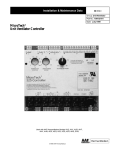
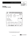
GENERAL DESCRIPTION
This manual explains specifications, handling, and operations of the A8PUE.
The A8PUE is a peripheral device that is used with the MELSEC-A series of
general-purposeprogrammablecontrotters.It
can-readfromandwriteto
sequence programs in a MELSEC-A series PC CPU.
TheA8PUE is also usedformonitoringandWstingdevices.Followthe
procedures in this manual when using the A7PUS to perform programI/O, as
well as inspection and maintenance.
1.1
Features
(1) A2A(S1) and A3ACPUare supported
All A2A(S1) and A3ACPU devices are supported.
(2)Expandeddisplayarea
The display area was expanded by using a back-lit LCD of 4 lines x 20
character.Therefore, inputting/editing/monitoring/testing of sequence
programs can be easily executed.
(3)
Easy keyoperations
Key operations are easier thanks to the Long key stroke.
(4) Accessing another station's PC CPU is enabled
Writing, monitoring, and testing of sequence programs can be executed
from the stationto which A8PUE is connected to another station (master
station/local station) on MELSECNET(II)/B.
(5) Writing when the CPU is in the RUN state is enabled
If the number of steps in a sequence program changes, the sequence
program can be changed when the CPU is in the RUN state.
(6) Extensivehelpfunctions
Helpfunctionsfor
reading/writing/inserting/deleting/monitoring/testing
operations in the menu selection format using dialog are supported.
(7) Easier control of parameters and sequence programs
Checking,revising,changing,inserting,andmonitoring
parameters and sequence programs is now easier.
1)
CPU
Example of changing a sequence program instruction
LD
OUT
LD
I
2)
-
ofPC
x0
Y20
X1
Change
LD
X0
MOV DO
LD
X1
Dl
1
Example of changing the T/C set value
The TIC set value can be changed in the menu format when the
CPU
is in the RUN state.
T/C SET VAL. CEO
The set value before changing is displayed.
Input the set value to be changed.
Input the device (timer or counter) whose set value
will be changed.
1-1
1. G-ENERAL DESCRIPTION
3)
T
1 5 B 1000
MELSEGA
Device memory monitoringexample
The device memory of a PC CPU can be easily checked.
T12: Set value = 2000, Current value = 1015,
Contact = OFF
T13: Set value =Current
23456,
value = 23456,
Contact = ON
T14: Set value = 200, Current value = 200,
Contact = ON
'Iate T15: Set value = 1000, Current value = 500,
Contact = OFF
500
Displays the current value
Displays the set value
the
:OFF
I ;ON
Devlce name
(8) Comments of each device can be displayed
The comment of the device where the cursor
is can be displayed by using
a help function.
1 0 ) Dl
PRBSBNT
D l comment is displayed.
c. VALUE
(9) Clockdisplay is enabled
Clock data in the PC CPU can be displayed. (The A8PUE turns the clock
data read request M9028 ON and OFF automatically.)
I
I..
ga/04/01
10.50.00
Displays
year,
month,
the
Displays the hour,
min,
and day.
and sec.
(10) Connections using the add-on or hand-held methods are enabled
There are 2 ways to connect A8PUE to a PC CPU.
[Add-on method]
Connects the A8PUE directly to a PC CPU.
[Hand-held method]
Connect the A8PUE to a PC CPU via an AC20R4-A8PU or AC30R4-PUS cable,
Back of the A8PUE
-
Connection site
AC30R4-PUS
RS-422 connector part
nnection site when using
AC20R4-A8PUE cable
1-2
1.2
Included Items
After buying the A8PUE, make sure the following items are included:
I
I
1
Model Namo
ABPUE
I
Items
I Programming
unit
Protective caps for the RS422 connectors
1 Amount I
I l l
1 2 1
Ram#ks
Placed on the connectors at
the factory
The following abbreviations are used in this manual:
(1) A8PUE
A8PUE Programming Unit
(2) ACPU
A-series PC CPUs towhich the A8PUE can be connected (see
Section 3.3.2).
(3)
:-;cpu
Including PC CPUs with the MELSECNET(I1) link function.
(Also including AlCPU + AlCPUP21/R21.)
(4) Peripheraldevices
All peripheral devices equipped with usable GPP functions
MELSEC-A series
1-3
in the
[BASICS]
t
.
2. LET’S TRY USING THE A8PUE
2.
‘MUSEGA
LET’S TRY USING THE ASPUE
It is possible to understand A8PUE operationsquicklybypracticing
the
creation and monitoringof actual programs.A very basic trainingprogram can
be created and its operations can be checked by using the
monitoring’test
function.
A simple example is shown below. Try to operate the A8PUE in accordance
with the example.
I
See Section 2
System configuration
I .......... Explanation of the system configurationusedfor
practice
See Section 2.1.1
Connections
.......... How to connect the A8PUE and an ACPU.
See Section 2.1.2
PC CPU
Memory all clear
.......... To input a new sequence program, all memory contents
(memory cassette) of an ACPU are cleared.
See Section 2.2.1
Sequence program
Writing
.......... A training sequence program is input by using the
A8PUE.
* See Sections 2.2.2 to 2.2.5
Sequence Program
.......... The input sequence program can be corrected by changinserting,
Correcting
ing,
and deleting.
I
See Section 2.3
.......... Bit devices and word devices of the training sequence
programs can be monitored.
Forcible ONlOFF of bit devices and the current values
of word devices during monitoring can be changed.
Completion
I
See Section 2.5
Help
~
~
~
~~~~~
1..........
Explanation of how to use the help functions
Since thissectionexplains
only thebasicoperations
of the A8PUE, see
Section 6 for greater details about operations and the contentsof each mode.
2-1
The system configurationto actually perform basic operations is shown
below.
[System configutetion]
CPU modulo
Power
supply
module
I
I
Output
module
Input
module
I
I
'1 : CPUs other than an A3ACPU can be used.
'2: Either install an actual switch on the outside or use
a simulation switch (A6SW16).
2-2
2.1
BeforeInputting a SequenceProgram
This section exdainshow to connect the A8PUE to an ACPU and how to clear
the entire memory (memory all clear) towrite a new sequence program to the
ACPU.
1
2.1 .l
Let’s t v connecting the A8PUE to an ACPU
1)
Connect the A8PUE to an ACPUas follows:
Tighten the anchor screws of the A8PUE.
2)
Put the ACPU in the STOP state.
3)
Turn ON thepower supply.
The display area of A8PUE can be switched as shown below.
COPYRIQHT(C) 1991
M I T S W I S E I BLBCTRIC
c- Displays the A8PUE software version
I
Then, key operations in all modes can be done.
Let’s try executing a memory all clear in the CPU so that we can write a new
sequence program to the ACPU.
When a key word is set, operate as shown in Section 5.1.3.
2-3
2.1.2
Let's try clearing all the memory contents of an ACPU
This. section shows how to dear aH memory contents (memory cassette) to
write a new sequence program to an ACPU.
[Sample operation]
@ [After the power is turned ON]
Q
[SHIFT l-4
PARAMJOTHERS
[MODE SELECT] is displayed.
1
Select the OTHERS mode.
Select '3 PLC SYSTEM'.
Select "2 ALL CLEAR'.
Select '1 PLC MEM. CLEAR".
'1 PLC MI"
CLEAR' is executed.
Memory clear completion size
All memory contents in the PC CPU
have been cleared.
I
Now, the input preparation for a sequence
program have been done, so let's try inputting a sequence program.
2-4
2. LET’S TRY USING THE A8PUE
2.2
Let’s Try Inputting a Sequence Program
This section explains
quence programs.
2.2.1
MELSEC-A
how to write, read, change,
insert in, and delete se-
Let’s try writing a new sequence program
Input the following sequence program:
0 LD
1 OR
2 ANI
3 OUT
4 OUT
5 LD
6 ANI
7 +P
14 END
t
X000
YO10
X001
YO10
TO
K10
TO
MO
K80 K5 020
Step Number: Displayed automatically when input
How to correct a wrong input:
Either see the operations in Sections 2.2.2 to 2.2.5 or execute a memory all
clear (see Section 2.1.2) and input from the beginning.
2-5
2. LET’S,.TRY
,.
USING
j4.s
THE
A8PUE
1
ClrlmibSEGA
[Sample operatlon]
0
\SHIFT
- . ...
I
READMRITE
Q ISTEP NUMBER
@[OR
0
Select the WRITE mode.
I
H0
Read step 0 .
GO
Y
I ANI
1
GO 1
GO
@ ] I D
@ IAN1
I
M
I
GO ]
GO]
: Both
the
are valid.
191
15)BOP
I
The sequence program has now been input.
Now, let’s try reading the input sequence program from a PC CPU to the ABPUE.
2-6
and
keys
2. LET’S TRY USING THE A8PUE
2.2.2
-.
.
MEr..,cEC-A
Let’s try reading the sequence program
This section shows how to read the sequence program written inSection 2.2.1
to check it.
[Sample operation]
R
A
A
Q [STEP NUMBER
7 D10
1 4 BUD
H 0 H GO ]
3
4
om
K10
Select the READ mode.
YO10
I
Use the [GO]key to scroll.
Now, let’s try moditying (change/insert/delete)
the sequence program.
2-7
2. LET,'S,TRY USING THE ASPUE
2.2.3
M W G A
Let's try changing (ovemritlng) an instruction
This section shows how to change the sequence program written in Section
2.2.1.
Before changing
1
1
3 OUT YOlO
r--1
4 OUT TO $1-01
0
1
I
Change the timer
sot vatue from KIo
to K100.
I After changing I
3 OUT YOlO
4 OUT
TO
The timer
value
sethas
now
been
changed from K10 to K100.
I
:?
Y
[Sample operation]
0
1SHIFT
--
I
READ/WRITE
I
W
A
4
I
I
7
K8O
4
KlO
Select the WRITE mode.
7 ) K5
Q ISTEP N U M B E R ~ G O
value
set
whose
step4th the
Read
will be changed.
Move the cursor to the set value
"K10' of TO.
4 1 K10
I
1
The set value of timer TO was written and changed
from 'K10" to "K100'.
Now, let's try inserting an instruction in the sequence program.
2-8
2.
LET'S TRY USING THE ASPUE
2.2.4
.MELSEC-A
Let's try insertlng (adding) of an instruction
This section showshow to insert an instructionto the program input in Section
2.2.1.
I Before insertina I
1
7 +
K80
14 END
K5
D20
TO MO
5
A MOV instruction has
now been inserted.
[Sample operation]
@
1 INSERTIDELETE 1
Select the INSERT mode.
no
6 MI1
Q
I S T E P NUMBER
15 nop
16 BOP
SP
IMOV-
KH2-
8
t-l
I
GO
1
I
14th
Read the
step ininwhich an
struction will be inserted.
19)PW
I
The 'MOV 020 K2Y018" instruction has now been
added to the fourteenth step.
Now, let's try deleting an instruction from the sequence program.
2-9
2.,44T:S TRY USING THE A8PUE
2.2.5
aElls€GA
,.
Let's try deleting an InstNctlon
This section shows how to delete. an instruction from the program written in
Section 2.2.1.
I Before deleting I
TO
IAfter deleting I
Delete an ANI MO
instruction.
I
I
5 LD
6 +P
TO
K80
K5
The ANI MO instruction.
D20
I
[Sample operation]
@[SHIFT
@I
HINSERT/DELETE~
STEP NUMBER
6
GO
Select the DELETE mode.
$i'f:'
I
struction
Read the will step
6th deleted.
be
an fromin- which
.
7
KO0
6
KSO
I
The cursor position instruction is deleted by using the [GO] key and step
numbers move up accordingly.
The 'ANI MO" instruction has now been deleted.
Now, let's try executing the sequence program and
monitoring it by using the ABPUE.
2 - 10
2. LET’S TRY USING THE A8PUE
2.3
ELSECIA
Let’s Try Monltorlng the Sequence Program
The sequence program writtenin Section 2.2.1 and modified in Sections 2.2.3
to 2.2.5 is shown below.
This section shows how to execute the sequence program and monitor a bit
device and a word device.
0 LD
X000
YO10
X001
YO10
TO
KlOO
LD
TO
+
K80 K5 020
MOV D20 K2Y018
END
1 OR
2 ANI
3 OUT
4 OUT
5
6
13
18
5
[General description of the operations]
The program is as follows:
Timer TO goes ON when X0 is turned ON. And then, Y18, Y l A , Y l C ,and Y1E
go ON after 10 sec. (The Y18, Y l A , Y l C ,and Y1E LEDs of the AY40’s output
module all light.)
Now,let’s try executingandmonitoringthesequenceprogramwritten
Section 2.3.1.
2-11
in
Pm l&T:q
2.3.1
TRY USING THE A8PUE
.
MElSEGA
Let’s tty monltorlng the exewtbn status d a Bragraar
This section shows
how to monitor the execution stateof a sequence program,
and how to check the current values of the ON/OFF states of bit devices and
word devices.
1
1 OR
2 ANI
YO10
X001
3 OUT
YO1 YO10
4 OUT TO
KlOO
0
1
[Sample operation]
(1)
Monitoring operation by using step number designation
@ Set the RUN keyswitch to RUN.
STEP NUMBER
GO
1
@ Turn ON the X0 external switch.
@ [About
10 sec. after X0 is turned ON]
E
8
8
l
Select the MONITOR mode.
0x001
111010
1 MI1
3)OUT
a MI
The current value of a timer is
displayed.
I: A bit device goes ON.
0 : A bit device goes OFF.
0x001
1YOlO
3)OUT
4 OUT
IT0
I
100
After the timer times out, the
current value becomes ‘100’.
1
The monitoring operation has now been checked by
using step number designation. Set the RUN keyswitch of the CPU to STOP and RESET.
Turn OFF the X0 external switch.
Now, let’s try checking the monitoring operation by
using device designation.
2 - 12
2. LET’S TRY USING THE A8PUE
MELSEC-A
(2) Checking the monitoring operation by using device designation
Monitoring device: D20
@Set the RUN keyswitch to RUN.
1
MON./TEST
1
OTO
4 OUT
o
HGO]
@ Turn ON the X0 external switch.
@ [About
10 sec. after X0 is turned ON]
The current value of a word device
is displayed.
HID
v
v
85
10
I
4
‘85” is stored in D20.
The monitoring operation has now been
checked by using device designation.
Turn OFF the X0 extemal switch.
Now, let’s try testing a device in the sequence
program by using the ASPUE.
2 - 13
2. LET'S,TRYUSING THE A8PUE
1.
* A I , *
2.4
Let's Try Testing the Sequence Program
This section shows how to execute and test the sequence program written in
Section 2.2.1 and modified in Sections 2.2.3 to 2.2.5.
2.4.1
Forcibly turning a bit device ONlOFF
or*Dd
This section shows how to check that Y 10 was turned ON forcibly, and that
the current value of TO became '100" after 10 sec.
0 LD
21 ANI
OR
x000
YO10
X001
[y@3l
3 OUT
4 OUT TO
Turn
Y10
KlOO
ON
forcibly.
Y10 has now
KlOO beenturned
ON forcibly.
f
1
[Sample operation]
rn
(1) Testing operation by using stepnumber designation (list monitoring)
0 Set the RUN keyswitch to RUN.
I
MON.TEST
I
u
4
o
SP M S H I F T ~
1
Select the TEST mode.
x100
Set Y10 to be turned ON forcibly.
I10 #ET
@
I T k [ A f t e r about 10 sec.]
g
3 om
4)Om
4
x100
polo
F O
100
Y10 has now been turned ON forcibly, and the current value '0' of TO
has now been changed to "100".
The testing operation of forcibly turning a bit device ON has now been checked by using step
number designation.
Set the RUN keyswitch of the CPU to STOP and
RESET.
Now, let's try checking the testing operation by
using device designation.
2 - 14
2. ,LET'STRY USING THE A8PUE
MELSEC-A
(2) Checking the testing operation by using device designation
(device monitoring)
@ S e t the R U N keyswitch to RUN.
I MON./TEST I
Q
IY
@
I SHIFT H SET ]
@ (GO]
I
t.lo
4
K100
H G O H S -H I0F T ~
v
TIY 010
Turn OFF Y10. ( 0 )
Set Y10 ON forcibly.
'TIY 010 I
v
v
Y10 has now been turne'd
ON forcibly.
The testing operation of forcibly turning a bit device O N by using device designation has now been
checked.
Keep the C P U in the R U N state.
The following checks testing operation to which the
current value of a word device is changed.
2 - 15
2. LET'S TRY USING THE ASPUE
r
2.4.2
MElsEGA
i..
Changlngthe current value of a word devke
This section shows how to perform the test which changes the current value
of D20 when the C-PU is in the RUN state.
1
II
5 LD
6 K80
+P
13 MOV
END
TO
5
K5 020
KPYOl8
The current
value has ngw
been changed.
II
Change
the
current value.
[Sample operation]
(1) Testing operation by using step number designation (list monitoring)
(Change the current value "85" of 020 to V S W . )
F L
Current value of 020
NUMBER
3
13 b D10
13 K2TOlS
G,O,h
*'' is displayed for a bit device
where a digit was designated.
Move the cursor position to 020,
and set 'K15' at D20.
13 1 010
3
C
P
v
v
6 D10
13 YOV
13 b 010
13 K1TO18
I
15
15
4
The current value "85"of D20
has now been changed to "15".
A display of output unit AY40
changes as follows:
Y1 E
"ON"
-
'ON"
Y1 B
The testing operationof changing the current
value of a word device by using step number
designation has now been checked.
Keep the CPU in the RUN state.
Now, let's try checking the test operation by
using device designation.
J
2 - 16
2. LET'S TRY USING-THEASPUE
:,
, - , I .
UE~SEC-A
1
(2) Checking the test operation by using device designation (device moni-
"
'
I
toring)
(Change the current value "15" of D20 to "240".)
0 H G O ]
$'"
10
TbD 1 0
I
Current
value
of D20
Set 'K240"
cursor
position
theat
The current value "15' of 020
has now been changed to '240".
A display of output unit AY40
changes as follows:
Y181
Y1C I
The testing operation of changing the current
value of a word device by deitiice designation
has now been checked.
Keep the CPU in the RUN state.
Now, let's try checking the testing operation in
which the set valueof a timer is changed when
the CPU is in the RUN state.
2 - 17
D20
2.43, .- .ChanQlng.theset value of a.tImer when the CPU Is In the RUN state
This sectionshows tiow to forcibly changethe set.valueof a timer of sequence
programs in the RUN state.
Change the set value "K100" of timer "TO" in the program to "K50"when the
CPU is in the RUN state.
0 LD
X000
YO10
2 ANI X001
value
3 OUT YO10
Change
set
4 OUT TO LRiiio7
value 'K100"
---A
to "K50'.
1 OR
set
The
been changed to
"K50'.
I
[Sample operatlon]
0
1SHIFT
PARAM.?OTH€RS
}
Select the OTHERS mode.
Switched to the menu display.
SET
I
I
VALWBI
I
I
I
VAL.
0
T / C BET
D8vIC8IT O I K
S E T VALWIK
CEO
501
50
Change a set value to "50".
1 PLC CEBCK
3 PLC SYBTBI
I
The set value of a timer could be changed.
Check that the set value of timer "TO" has now
been changed into 'KSO'(see the operation in
Section 2.2.2).
This completes the basic operations of the
ASPUE.
Now, let's try using the help functions.
The basic operations of the help function are
explained in Section 2.5.
2- 18
2. LET,'STRY USING THE A8PUE
2.5
MELSEC-A
Let's Try UslngHelp
The [HELP] key is pressed when using the help functions.
The help function items of each mode are displayed in a menu format by
pressing the[HELP] key. Therefore, corresponding items can be selected and
executed.
This section explains, as sample operations, the reading operation by using
instruction designation and the changing operation of the display format of a
current value.
2.5.1
Readlng an instruction In a sequence program
This section explains how to read the place where the "MOV" instruction is
used in the sequence program.
[Sample operation]
@
HELP
I
1:COp[BNT DIEPLAY
CLMR:BND
1 :BTEP
1:I€fSTRDCTIOB
KEY IW IIRTRDCTION
KEY IN IBSTRUCTIOB
[YOV I
R
*
A
6
D10
13
13
010
13bYOV
K1YOl8
13)YOV
13 D2O
Press the [HELP] key in the READ
mode.
Select " 1 : READ'
Select "2: INSTRUCTION'
Set the "MOV" instruction.
'MOV D20 K2Y18' of the 13th step
isread.
Message when there is not a 'NOW
instruction in the steps after 13th
Reading an instruction by using the help function instruction designation has now been completed.
Now, let's try changing a current value display format.
2.5.2
Changing of the display fomat of a current value
This section shows how to change the current vatue display format in the
MONITOR mod6 from decimal to hexadecimal display.
[Sample operatlon]
Seieot the MONITOR mode.
13)MOV
13 D10
current
thevalue
'240'
of
played in decimal.
disD20
is
I
*
Press the [HELP] key in the MONITOR mode.
1:BIJIIBBB FORMAT
1 :MOWITOR
I
CLEAR :E g D
Select "1 : NUMBER FORMAT'.
a :mc
5
6 D10
H
13)MOV
13 DZO
H
13 KOYOl8
OOPO
OOPO
I
Select '1 : HEX".
The current value '240' of D20 has
now been changed to the hexadecimal display
.
. 'HOOFO'.
1
I
4
Changing the display format of the current value by using
the help function has now been completed.
The help function basic operations have now been completed.
Section 3.4.2 gives a detailed list of the help functions of
each mode and their purposes.
SF
When the number of pa es is displayed on the upper right hand side of a
help screen, press the[ ] and [k] keys to change the pages on the screen.
u-,
,
Page display example
Page currently displayed
Total number of pages
2-20
[DETAILS]
3. SPECIFICATIONS
,
,
3.
SPECIFICATIONS
3.1
General
Specifications
..
,
'
; MECSEC-A
Table 3.1 A8PUE General Speclficatlons
[
Items
Ambient temperature
Ambient humidity
Specifications
Operating
Storage
0 to 40 "C
-20 to 70 "C
Operating
Storage
20 to 85 %
RH, no condensation
10 to 90 % RH, no condensation
Frequency
Vibration resistance
Conforms to 'JIS-COS1 1
10 to 55 Hz
Acceleration
-
9.8 m/s2 (1G)
JIS-CO912 (10 g x 3 times in 3 directions)
55 to 150 Hz
Shock resistance
Operating ambience
Cooling method
Conforms to
Amplitude
0.075 mm
(0.003 inches)
-
Sweep Count
10 times
(1 octave/minute)
No corrosive gases or dust.
Self-cooling
*JIS: Japanese Industrial Standard
3.2
Performance
Speclfications
Table 3.2 A8PUE Performance Specifications
Items
Connected module
Power,
current consumption
Connection method
LCD display
Operating method
Key operation check
Display lifespan
Backlight lifespan
Keypad lifespan
External interface
Outside dimensions
mm(in.)
Weight kg(lb)
ACPU (see Section 3.3.2)
Specifications
Power supplied from connected ACPU (5 VDC, 0.4 A)
Add-on
Attached directly to the ACPU.
Connected via RS-422 cable. Hand-held
Display of 4 lines x 20 characters (with cursor)
Consists of 54 operation keys (covered with polyurethane film)
Buzzer
100000 hours or more (when using the unit at 15 to 35 "C ambient
temperature and 65 % RH or less ambient humidity)
50000 hours or more (when using the unit at 25 "C operating ambient temperature)
If ON, goes OFF if a key has not been input for 10 minutes.
1000000 times
Add-on connection and
Rear side of the unit
AC30R4-PUS cable connections
RS-422
AC20R4-AEPUE cable
Right side of the unit
connections
Extended
Unused
Upper side of the unit
interface
lEa(7.40) (height) x 9543.74) (width) x 44.5(1.75) (depth)
When installed onto an ACPU, the depth i s 37.5(1.48).
0.5(1.1)
3-1
MELSEGA
3.3
System Configuration
This section shows the system configuration and system equipment when
using the A8PUE.
3.3.1
System configuration
The A8PUE is connected to and operateswith an ACPU by using either of the
following methods:
I
I
I
Methods
Connoctina
Add-on
method
]Attach
Hand-held method
(1)
Add-onmethod
r
I
I
How to Connect
the ABPUE directly
to
the ACPU.
Connectthe ABPUE and ACPU viaRS-422cable.
R
1
I
I
I
Programming
unit
ABPUE
(2)
Hand-heldmethod
;
<
I
AC20R4-AaPU
AC30R4-PUS
A8PUE
i
i
,n
i
I REMARK 1
Section 3.3.2 gives connectable ACPUs.
3-2
3. SPECIFICATIONS
MEL,CFC-A
3.3.2 ConnectableACPUs
ACPUs to which the A8PUE can be connected are asfollows:
T
Connectable ACPUs
AOJPCPU
AOJ2HCPU
A1 CPU, AlNCPU
A1 SCPU
AZCPU(-Sl), A2NCPU(-S1)
A2CCPU(C24/PRF)
APACPU(-S1)
A3CPU, A3NCPU
A3 AC P U
ABHCPU
A3MCPU
ABVCPU
A73CPU, A373CPU
POINT
Add-on
Applicable to other
than an A1S and
A2C(C24/PRF)
1
Connecting Methods
Hand-held
AC20R4-A8PUE
Cablea
Cables
Applicable
Applicable
I
The A8PUE uses power from the connected ACPU.
Since the current consumptionof A8PUE is 5 VDC and 0.4 A, the power
supply and the capacity of the total internal current consumption of a
connected ACPU must be taken into consideration when connecting the
ABPUE.
3.3.3
System equipment
The following table shows the equipment needed to use the A8PUE.
I
I
ABPUE
AC20R4-ABPU
AC30R4-PUS
I
I
programming
unit
RS-422 cable
RS-422 cable
I
I
Programming unit with an LCD and
function
programming
Cable for connecting the RS-422 connector on the right side of the ABPUE
to an ACPU
Length: 2 m (Option)
Cable for connecting the RS-422 cannector on the rear side of ABPUE to
an ACPU
Length: 3 m (Option)
I
I
0.5
0.2
0.5
I
I
3.4
Lists of Functions
3.4.1
List of fumtlms
Function8
Writing pi&jranis
'
Purpsu
'
Device change
Instruction display
NRlTE (W)
Help
NOP continuation
Comment display
Reading programs
3EAD (R)
To write,
insert,
change
andprograms
To change devices used in d d g n a t e d steps in
proprams
Display/selection of imtructianr that begin with
the designated cheisctm
To designatestepnumbers
and readprograms
To make designated ranges In programs with
NOP
To display
comments of designated
devices
To designatestep numbera and readprograms
To designate utilized instructiohs and read programs
To displayprogramsrandtodesignatedsteps
bv scrollino a u t o m a t W
Automatic scrolling
~~~~~~~~~~~~
~
~
~
6.2.2
6.2.2
6.2,3
-
6.2.1
6.2.4
6.3.1
6.3,2
I
6.3.4
~~
Same as the purposes of the read and automatic scrolling funcrions.
Automatic scrolling
To displav comGnt8 of desimated devices
~~
~
To insertnew
Insertinn in DroPrams
~~
Dronrams in existing Droarams
instruction display
NSERT (i)
Help
6.4.1
ignated positions
COPY
ignated positions
To display
comments
Comment display
Deletion
6.4.3
of designated
devices
To delete
programs
of designated
steps
To delete
designated
ranges in programs
To batch-delete NOP instructions in programs
up to the END instructions(NOPLFinstructions
are not deleted.)
To display
comments
designated
of
devices
To read programs of designated steps and display the continuity of instructions, ON/OFF
states of contacts, and current values
To search and displayOUT/SET/RST instructions using designated contact devices (Monitoring continues.)
To display current values (including T/C set vaiues) of the ON/OFF states of bit devices and
word devices
To display values in designated formats or
ASCII.
To read and monitor programs of designated
Range designation
NOP batch
Comment display
List monitoring
Monitoring search
Device monitoring
AONITOR (M)
6.2.4
I
To copy designated ranges in programs to des-
Deleting progrqms
JELETE (D)
I
Step read
Inseftion
I
I
Display change
List monitoring
StBDS
Same
the
as
monitor
search
function.
To display current values (including T/C set values) of the ON/OFF state of bit devices and
word
To set displays of offline
switchs
To display
comments of designated
devices
Help
Device
monitoring
devices
Comment display
6.2.4
6.5.1
6.5.2
6.5.3
6.2.4
6.6.1
6.6.2
6.6.3
6.6.4
l I
-
lI
I
6.6.5
6.2.4
(Continued on thenext page.)
3-4
3. SPECIFICATIONS
MELSEC-A
(Continued from the previous page)
Functions
~~
TD set(turn ONyreset(turn OFF) bit devices
To chanoe current
values
of word devices
To sewcancel offline switchs and separate des-
~
Testing by list monitoring
set(nnn ON)lreset(turn OFF) bit devices, and
to change current values of word devices
Same as the Test bv list monitorina
List monitoring test
To display current values (including T/C set values) of the ONlOFF state of bit devices and
word devices
To displav comments of designated
devices
To only clear parameters
an
in
ACPU
Device monitoring test
Comment disDlav
All clear oIf Darameters
PARAMETER
P)
l1
I
To set memory capacities. timer counters, and
latch ranges, etc of all kinds of parameters
Or to chanoe set values
To set entry codes
Or to change entry codes
To change set values of designated devices
fT/C)
To display the descriptions of errors that occur
inan ACPU and the step numbers where errors
occur
To check duplex coillinstruction codes, etc. in
programs
Setting of parameters
Change of TIC set values
PC check
6.7.3
6.7.4
To chame current values of word devices
To display values in designated formats or
ASCII.
Display change
Help
6.7.1
6.7.2
from ACPU operation processing. Or to cancel
Test by device monitoring
TEST (T)
I
Error step read
Program check
6.2.4
6.8.1
6.8.2
5.1.3
6.6.2
6.9.1
6.9.2
6.9.3
Link monitoring
Monitoring Buffer memory batch monitoring
I
Clock monitorino
To clear the entire memory of ACPUs and return to initial states
To clear currently selected programs (mainpub)
To clear all device memories except special D
and swcial M and R
I
To switch applicable operating programs in all
ABPUE modes.
To switch applicable operating programs
(mairvsub) in all ABPUE modes
To forcibly switch ACPU execution states
(RUN/STOP)
To read and write in machine language for the
memory of ACPUs
To set whether or not writing is executed when
programs are in the RUN state, and whether or6.9.14
not only the MONITOR and TEST are utilized.
To set whether or not the continuity of each inmonitoring
struction i s displayed when the list
function is used.
To set whether or not buzzer is ON/OFF when
a key is pressed.
PC memory
OTHERS (0)
PC
system
All clear
Program
Device memory
Switching
Others
PC NO. setting
I
Mairvsub switching
Remote RUN/STOP
lwritina
Program mode selection
PU
setting
nated addresses for the special-function
mod6.9.5
Continuity display
Buzzer setting
3-5
6.9.7
6.9.8
6.9.9
6.9.10
6.9.11
6.9.1 2
6,9,,3
6.9.15
6.9.16
3.4.2
klstof help functbns
The following table shows the help functions for eachmode. Operate the help
function Without using the reference section in accordance with the items in
each help menu;
Modor
Holp Fundlonr
(Modo Dirplryr)
Instruction displaylselection
Continuous miting (range) of
'
Continuous writing (all) of NOP
Comment display
Read by
step designation
Read by using an instruction
READ (R)
.,
,
Read by using a device
Automatic scrolling
Comment display
Instruction display/selectlon
NSERT (I)
Read by using step designation
Batch mOYementof programs
Batch copying of programs
Comment display
To input initials and display instruction names that correspond to
tu& initials in lists
To select instructions to be written
from lists
To designate step numbers in which
instructions are written and to display
wwrams
I
To designate start and final step numbers and execute NOP batch writing
To designate only start step numbers
and execute NOP batch writing until
the flag step
To disptay comments of devices
where the cursor is
To designate step numbers and display programs
To input instruction names and
m r c h Drograms
To input device numbers and search
programs
To scroll programs automatically in
desienated directions
To display comments of device where
the cursor
is
.~
To input initials and display instruction names that correspond to such
initials in lists
To select instructions to be inserted
from lists
To designate step numbers in which
instructions are inserted and to dispiay programs
To dedgnate step ranges and move
I
-
0
0.2.3
l o l -o l -
I. -
Step read
WRI
Normal
Roforonco
Soctlons
Oporrtions Oporrtionr
Holp
Purpotor
I
~~
in batch
To designate step ranges and copy
them in batch
To display comments of devices
where the cursor is
0
0.2.1
0
-
0
-
0.2.4
0
0
-
0
0
-
0
0
0
0
0
I
-
I
0.2.4
0
-
0.2.3
0
0
-
0
0
0
-
0.4.2
0.4.3
0.2.4
* 1 : See (2) and (3) in the Explanations part of Section 6.3.2 for the instruction to be set.
(Continued on the next page.)
3-6
t
3. SPECIFICATIONS
MELSEC-A
(Continued from the previous page)
. I
Holp Functlons
Batch deleting of programs
IELETE (D)
NOP batch delete
Comment display
Changing display formats
Read by using step designation
WONITOR (M)
Monitoring search
Monitor device
, .-
Setting of an offline switch display
Comment display
Changing display formats
rEST (T)
Read by using step designation
Device monitoring test
Comment display
ITHERS (0)
'2
Changing display formats
I
To designate step ranges and delete them in batch
To batch-delete NOP instructions
To display comments of devices
where the cursof is
To change displayed numerical values to binary, octal, decimal, hexa
decimal, and ASCil displays
To designate step numbers that do
list monitoring and display programs
To move the cursor to contact instructions and search the corresponding OUT, SET, and RST
instructions
To designate devices to be monitored and display devices and d e
vice states
To set whether or not there is an
offline switch display during device
monitorina
To display comments of devices
where
.. . . the
. . cursor
.- .. is
.
To change displayed numerical vaC
ues to binary, octal, decimal. hemdecimal. and ASCII disdavs
To designate step numbers in
which list monitoring is tested and
to display programs
To designate devices which device
monitoring is tested and display devices and device states
To display comments of devices
where the cursor is
To change displayed numerical values to binary, octal, declmal, hexadecimal, and ASCil displays
'2: Can be executed only during buffer memory batch monitoring.
3-7
Normal
Holp
Purposes
Oprstlons
Rofonnto
Soctlons
Oporrtlons
-
0
0
6.5.2
6.5.3
A
0
-
0
-
6.6.4
0
0
-
0
0
-
6.2.4
l o l o l 1 I - 1
1
0
0
1
-
I
6.6.5
6.2.4
0
-
6.6.4
0
0
-
0
0
-
0
-
6.2.4
0
-
6.6.4
4.
. .
M A N W f f i AND,HOMENCtATURE
I
This sectlon tells how to handle the A8PUE and explains the part names
4.1
Precautlons When Handllng the,MPUE
7
The following precautions should be taken when handling the A8PUE:
(1)
Since the case is made of plastic, do not drop the A8PUE or subject it to
severe shocks.
(2) Do not disassemble the case (doing so could cause a malfunction).
(3) When not using the A8PUE, handle the RS-422 connector as follows:
1) Attach the cover to the RS-422 connector on the right side of the
unit.
2) Attach the protective cap to the
of the unit.
n'
L:i
RS-422 connector on the rear side
i
4
(4) Whenusingthe A8PUE, the RS-422 connectornotused
to an ACPU should have its cover
protective
or cap
on.
for connection
4
I
I
(5)
Do not removetheconnectorcover
upper side of the unit.
(6)
Do not touch the RS-422 connector pins (doing so could cause a malfunction).
4
of the extension interface on the
(7) Do not remove the cover of the A8PUE.
Do not loosen the screws that hold the cover (doing
malfunction).
?
so could cause a
(8) Always press the [CLEAR] key before disconnecting the A8PUE from an
ACPU.
(9) Never use a cleaning agent such as thinner, alcohol, or freon.
(10) Press keys only with the fingers.
sharp
Using
instrument,
a
etc. could
malfunction.
cause
a
Sincethe A8PUE beeps when akey is pressed, key operations canbe
confirmed by the sound.
IMPORTANT
d
I
I
When designing the system, to protect the PC, make sure to provide a
safety circuit outside thatsystem.
I
I
4-1
I
f
4. HANDLING AND. NOMENCLATUR&
_,,.
:
4.2
a*_.
,.
,
,
,
,
MESC-A
Nomenclature
This section shows and explains the nomenclature of the A8PUE.
(Front view)
Anchor
screw
Liquid
'2 crystal
display
(hereafter referred to as the display.)
interface '1
Operation keyboard
thumbwheel
Anchorscrew
*2
'1 The connector for an extension interface cannot be currently used.
Do not remove the connector cover.
'2 The anchor screw (M3) tightening torque is (39 to 49 N.cm 4 to 5kg.cm).
(Rear view)
RS-422 connector
For connection vi
RS-422 connector (with protective cap)
For connection using the add-on method
For connection via ACBOR4-PUS ceble
4-2
4. . I D L E N G AND NOMENCLATURE,
-
4.3
. .
.
......I
,.
’.
. MELSEC-A
, :-x
Layout of the Keyboard and List of Key Functlons
This section gives the layout of the ABPUE operating keyboard, and lists the
keys and their functions.
key
I
1) Control
. .( 1.)
2) Mode keys
(keys used to select the operating mode)
3 ) Help key
1
-4) Instruction keys (Instructions on the top)
’
Device keys (Codes on the bottom)
1) Control keys (2)
Numbers.
r
I
1
Names
Keys
>ontrot key
5) Instruction keys (Instructions on the top)
Devico numberkonstant setting keys
(0 to F on the bottom)
Mrin
Rofrronto
Functions
Sootions
Used to declare start inputting step numbers or for automatic
2 and 6 give examples of its use.
Used to make the bottom functions of a key valid.
The tophottom setting can be confirmed by the display.
Used to make the top functions of a key valid.
The tophottom setting can be confirmed by the display.
(,,,)
5.4.1
In modes other than PARAMETER, OTHERS, and help function modes:
Used to return to the mode selection state.
(All input instructions or device numbers willbe cleared except the mode.)
Used to correct a mistake when the wrong key is input.
6
Jn the PARAMETER mode:
Used to interrupt processing. After processing has been restarted, continue operations as before.
6.8
Returns to the previous display in the OTHERS mode.
6.9
When the help function is used:
Returns to the display when the [HELP] key was pressed.
ISP*CE)
2
6 scrolling. Section
6
When disconnecting the A8PUE from an ACPU:
Processing of A8PUE during execution is interrupted.
Be sure to press the [CLEAR] key before disconnecting them.
5.1.5
Used to input a blank between an instruction part and a dename
vice
Used to move the cursor ( b , ) on the display or indicate the
scrolling direction of a scrolling display.
6
Pressed at the end of a series of key operations. Key operations are executed until this key is pressed. Press this key
after confirming the contents of the series of key operation in
the display.
6
~
~~
(Continues on the next page.)
4-3
4.. HANQLENG AND NOMENCLATURE
,
BRELSEC-A
,
(Continued from the previous page)
Functions
2)
3)
4)
Mode keys
Used to selectABPCIE modes.
The top and bottom modes can be switched by pressing the
[SHIFT] key.
::gk
a
Help key
InstructionlDevice
keys
5.1.4
2.5
6
Used to select the help function in the mode supporting a
help function (Sections 2.5, 6.2 to 6.7, and 6.9.5. give detajls about applicable modes.)
Used to input WH when instructions, device names and constants are input.
Pressing the [SHIFT]or [STEP NUMBER] keys enables
switching the vaIid key area between the top and bottom.
Instruction/
Device number/
constant
settina
kevs
switchina
the
valid
5.4.2
5.4.1
Used to input instructions, device numbers, and constants.
Pressing the [SHIFT] or [STEP NUMBER] keys enables
kev area
between
the
too
and
bottom.
The following shows the movements between the steps, between menu
items, and in the input area.
(1)
Repeated pressing of the cursor keys move the cursor in the designated
key direction.
(2) Movement between menu items or between steps
To display the programs immediately before
or after a currently displayed
instruction, press the [ I/[ 1] keys.
[ t ] : Program immediately before (the program nextto step 0 will not
change)
[ 1 ] : Program immediately after (the program next to the final step will
not change)
Ip~-I_L.:oI:LLol~,::-L~x_Lo10,15L-:-L1
. . .
I
i N i D i i i,i
.M_i_2ii i i i
r-1;1 1 t j AEt;T,--rr7
I STtor-rr7-r-
I
I
-24-1-1
-t-l-tl-ti-i-tl-+l-t-t-l-tl-ti-rI
131
I
1K1112131I
I
I
I
I
I
I
I
"bncan move in a designated direction (up
or [
1 ] key.
and down) by pressing [ 1' ]
(3) Movement in the input area
Press the [(+)I/[(+)]
keys to move the cursor among instruction names,
sources, and destinations.
~
-
~
~
~
- W I - I J ~ ~ I _ OICI-DL-I-L
L
7
I11211I)?NlOlPl
~
~
~
~
IMI~II I I I
I 1-l-~-I-T-l'T7'1-I I
-
~
M
~
~
-
~
-pt-l-tl-ti-rtl-+i-~t-l-tl-ti-~
T
I
1 ~ 1 2 1 ~ , 4 1 7 1 4 1 ~ 1 ~l 1~ 6l 1~ 4l 1o ~l 1
o
display
a
This
isexample
when
has been input.
l )
o -l ~
inputarea
DMOVP K2147483647 Dl000
.Wn can move in a designated direction (right and left) by pressing the
[(+)I or [(-+)I key.
4-4
~
-
ENCLATW
.
,
MEL4SEG-A
In this manuJ, AWUE key operations are abbraviated as follows:
[Key n]: This means all keys between [Key 11-and
(1) [Key 11 + [Key 21 +
[Key n] are pressed in order.
(2) [Key. 11 + [Key 21: This means that both [Key 11 and [Key 21 are pressed
simultaneously.
(3) Keys such as
I%>and m k e y s which are used
for dual purposes
(instructionanddevice/constantinput),andthecontrolkeys
of the
A8PU6 are referred to as follows:
(a) The mode instruction or alphanumeric character which corresponds
to the purpose of those keys.
r
Example:
+ [RST] or [O],
+ [MOV] or [MI
1
1
(b) When an instructiqn inpytis explained, the explanation uses only the
instruction symbol. (The alphanumeric character is omitted.) When
an alphanumeric character input is explained, the explanation uses
only the alphanumeric character. (The instruction name is omitted.)
Example:
When the
key
referred
is
to:
When an instruction input is explained:[MOV]
When an alphanumeric character input is explained:
1
[MI
1
!
(r
4-5
4. HANDLENG AND NOMENCLATURE
..
4.4
MELSEC-A
Maintenance
Exceptforthebrightnesscontrol,the
require inspection or replacement.
A8PUE has no componentswhich
Rules for storing the A8PUE:
(1)
Do not store the A8PUE in the following environments:
Where ambient temperature is outside the range of -20 "C to 70 "C.
0 Where ambient humidity is outside the range of 10 to 90 O/O RH.
0 Where condensation occurs due to sudden temperature changes.
0 Anywhere the A8PUE might be exposed to wind, rain, or the direct
sunlight.
Anywhere with excessive amounts of conductive powders (such as
dust, dirt, and iron filings) or corrosive gases, oil mist, and salt.
(2) When storing, make sure the protective cap is on the RS-422 connector
on the rear side of the A8PUE.
(3) When storing, make sure the cover is on the RS-422 connector on the
right side of the A8PUE.
4-6
5.
OPERATING PROCEDURES
This section expiains the operating procedures from the time the A8PUE is
connected to an ACPU until it is disconnected, as well asrelated window
displays and basic operations.
5.1
Procedure From the Beginning t 0 the End of the Operation
I
I
Stan
1
Connect the ABPUE and
ACPU.
an
....................................................................
See Section 5.1.1.
(Automatic displayed after about 14 seconds.)
iABPUE
ACPU
R ....................................................................
nected
andversion
the
I
See Section 5.1.2.
switched after a b u t 1 second.)
Vi
the key word is registered
..............................................................
......See Section 5.1.3.
......See Section 5.1.4.
according
to Section
(Mode switching)
DELETE
MONITOR
Operation
according
to Section
Operation
according
to Section
according
to Section
PARAMETER mode
OTHERS
Operation
according
to Section
Operation
according
to Section
c
T
[RST] + [GO] (resets the ABPUE)
..................See Section 5.2.
(Operation completion and disconnection)
....................................................................
............................
5-1
See Section 5.1 5 .
a
I
,n
5. OPERATING PROCEDURES
5.1.1
BllElSEC-A
Connectlng the AIPUE to an AWU
Although the A8PUE can be connected to an ACPU even while it is running,
Mitsubishi recommends connecting the ABPUE to an ACPU while it is in the
STOP state. If it must be connected while in the RUN state, make sure to
insert the connector properly.
(1 )
Connection using the add-on method
In this method, the A8PUE is installed directly onto the ACPU module.
However, the add-on methodcannot be used for connecting an A I S and
A2CCPU(C24/PRF) because screws cannot be tightened.
Connect then using the hand-heldmethod.
A8PUE anchor screws
t
1
\ RS-422 connector
The connection procedure is as follows:
1) Remove the cover of the ACPU’s RS-422 connector.
2) Remove the RS-422 connector protection cap from the rear
ABPUE.
Put the protection cap in a safe place.
of the
3) Connect the A8PUE to the RS-422 connectorof an ACPU, and firmly
tighten the A8PUE anchor screws.
Tighten the anchorscrews at a torqueof 39 to 49 N.cm (4 to 5 kg.cm).
4) About 14 seconds after the connectionis completed, both theA8PUE
software version and the ACPU model name will be displayed.
5. QPEWTING PROCEDURES
,
>_.A_,.
.
- .
~
U&LS€GA
(2) Connection using the hand-held method
Connect the A8PUE to an ACPU by using the RS-422 cable.
The connection procedure isas. follows:
1) Remove the cover of the ACPU’s RS-422 connector.
2)-1 When using an AC30R4-PUS cable
Remove the RS-422 connector protection cap from the rear
of the
A8PUE.
Put the protection cap ina safe place.
2)-2 When using an AC20R4-A8PU cable
Open the cover
of the RS-422 cable on the right side
of the A8PUE.
/
q
q
3) Connect the A8PUE to the ACPU using the RS-422 cable.
fa,
Rear of A8PUE
I
I
W
I In the case of AC30R4-PUS
of AC20R4,.A8P U
‘1 Firmly tighten a anchor screws of the connector.
4) About 14 seconds after the connection is completed,
both theA8PUE
software versidn and the model name of the connected ACPU will
be displayed.
5-3
,, ,
4
.........
. . . . . . .&..
. .............
.
,**..
.
1,
5. OPERATING
,,,
PROCEDURES
......
:
5.1.2
J.
/
,
I
.
#
.
-
,
e
MELSEC-A
A8PUE software verslon and CPU model name display
After (a) completing the connection with an ACPU, or (b) resetting (pressing
the [FIST] + [GO] keys) the A8PUE, the A8PUE software version and CPU
model name are shown in the A8PUE display.
Confirm the display contentsas shown below.
I
rModel name
of the connected ACPU '1
Software version
of the ABPUE
I
8
_-
*1: The following list shows the con-
nectableACPUsandmodel
names which can be displayed.
I Connected ACPUo I
I AOJ2CPU
I
Model
Names
AOJ2
AOJ2HCPU
A2
AlCPU
A1
AlSCPU(-Sl)
A1S
APCPU(-S1)
A2
APNCPU(-Sl)
A2
A2CCPU(C24/PRF)
APACPU(-Sl)
A2
A3CPU
I
I
I
I
Connect an ACPU and the A8PUE.
Or reset the.ABPUE.
-
A3VCPU
I
...........See Section 5.2.
A
CPU model name are displayed.
About 1 second
,""'
: If the key word is :
: registered in the :
:L -connected
ACPU. :
---...........
J
"""""'q
I
See Section 5.1.3
operation.
Key
and
input.
word
A2A
A3
A3ACPU
A3HCPU
A3MCPU
...........See Section 5.1.1
About 14 seconds
A3NCPU
A3H
I
A3M
A3
5-4
,.
"--""-""'-""'.------.--: When
the
unit
connected
is
to an
:
: AOJPCPU
or
if an key word is not
:
: registbred
the
in
connected
ACPU. :
...............................
7
See Section
5.1.4
Mode
selection
5. OPERATING PROCEDURES
,.
5.1.3
,
.;MWEC.A
i
Key warp Input
I
When aconnected ACPU or the PC NO. of the ACPU tobeoperatedis
switched, if t h e key word is registered in the ACPU, the A8PUE requests an
input of theregisteredkey
word.
Input the key word registered in the ACPU. Then, press the [GO] key.
If the key word is not registered in the ACPU or the A8PUE is connected to
an AOJ2CPU, theoperation shown inthissectionisunnecessary.
(The
A8PUE automaticallygoesintothe
mode and function selection shown in
Section 5.1.4.)
I
I
I
Model name of the connected ACPU
@Software
version of the A8PUE
VBR.
L
L J
.............. See Section 5.1.2
and CPU model name are
1
i
I Request the key word input.
Input the key word registered in the ACPU to which
the A8PUE is connected.
Then, press the [ G qkey.
A key word can consist of
up to six characters. Input
the
key word by using the
device number/constant
setting keys (0to 9, A to F).
The A8PUE checks the
After
resetting
the
ABPUE,
if the key word is input incorrectly, repeat the operation from Section 5.1.2.
7
1
GO
KEY WORD- [ 0 4 0 4 1 1 ] ,
Input .the key word (04041 1)
Display when the input key
word is correct
-\
v
The result of the check is displayed for
about 2 seconds.
See Section 5.1.4 Mode selection and operation.
Display when the input key
word is not correct
'1
'1: If the key word which
was input does not correspond with the key word
registered in the ACPU, only the following operationscan bedone (Section
6 gives details):
MONITOR mode
Device monitoring ....................
See Section 6.6.3
Monitoring the offline switch
TEST mode
7
OTHERS mode
POINTS
1
Test by device
monitoring
.....
........
See Section 6.6.5
See Sections 6.7.3 and 6.7.4
Settingkanceling the offline ..... See Section 6.7.5
switch
-E
Error step read ........................
See Section6.9.2
Monitoringlswitching the PC ..... See Sections 6.9.4, 6.9.5,
6.9.6, 6.9.10, and 6.9.11
system
See Sections 6.9.14, 6.9.15,
PU setting ...............................
and 6.9.16
When operating in modes other than MONITOR, TEST, and OTHERS, if the key word registered in the ACPU is unknown, see the
"PC memory all clear" operation shown on the next page. And
then, clear(delete)theunknownregisteredkeyword.
If"PC
memory all clear" is executed, all other user data (such as sequence programs) will also be cleared.
Section 6.8.2 gives details about when (a) the key word registered
in an ACPU is changed, or (b) a new key word is registered.
5-5
ca
5. OPERATING PROCEDURES
MELs€GA
Allclear of parametersandasequenceprograms
as well as keywords
registered in an ACPU is enabled by the following operationwhen a key word
input is requested:
(Procedure 1 )
Key word input request is displayed.
(Procedure 2)
ACPUSTOP operation
Put the ACPU in the STOP state,
(Procedure 3)
PC memory all clear operation
Input "ALLCLR", and then press the [GO] key.
(Procedure 4)
PCmemory all clear processing display
When memory all clear processing by the A8PUE begins, the screen
shown on the left is displayed, and the display on the "*" line and the
number of whole bytes changes sequentially.
ALL CLEAR
's (max. lO/time) are displayed in accordance with the memory capacity to
the s' disappear one by one during memory all clear processing.
be cleared, and
* represents 10 YO of the memory capacity.
The memory capacity (number of whole bytes) to be cleared is displayed in units of K bytes
and it decreases by 1 K bytes during memory all clear processing.
(Procedure 5 )
Completion of PC memory all clear processing
When memory all clear processingby the A8PUE has been completed,
a buzzer sounds.
The screen is switched to the
one shown on the left. (State before
selecting the A8PUE mode)
( W )(MOBITOR)
(INSERT) (PARAMBTER)
(Procedure 6 ) Thenextoperationbegins
Select the mode in accordance with Section 5.1.4, and start the next
operation.
5. OPERATING PROCEDURES
5.1.5
MELSEGA
Dlsconnectlngthe A8PUE f m an ACPU
(1)
Disconnection when the add-on method is used
The disconnection procedureis as follows:
1 ) Press the [CLEAR] key.
2) To disconnectthe
anchor screws.
A8PUE from anACPU,
unscrewthe
A8PUE
3) Disconnect the A8PUE from the ACPU.
i
4) Put the stored protective cap back on the RS-422 connector on the
rear side of the A8PUE.
5) Put the cover on the RS-422 connector of the ACPU
6) Store the A8PUE carefully.
(2) Disconnection when the hand-held method is used
The disconnection procedure is as follows:
1) Press the [CLEAR] key.
2) Unscrew the connector anchor screws of the ACPU, and remove the
RS-422 cable from the ACPU.
3) Put the cover on the RS-422 connector of the ACPU.
4) Method for removing RS-422 cable from the A8PUE
(a) When AC30R4-PUS cable is used
Unscrew the connector anchor screwof the A8PUE, and remove
the RS-422 cable from the A8PUE.
Put the stored protective cap on the RS-422 connector on the
rear side of the A8PUE.
(b) When AC20R4-A8PU cable is used
Remove the RS-422 cable from the A8PUE.
Put the stored protective cap on the RS-422 connector
right side of the A8PUE.
5) Store the A8PUE and RS-422 cable carefully.
in the
5.2
How toResetthe A8PUE
This section tells how to reset the A8PUE during operations.
After rese?thg.theA8PUE, resume operations inaccordancewithSection
5.1.2 A8PUE software version and CPU model name display.
Execute the operation using
the ABPUE.
5-9
*
J
5. Q,PERATINGPROCEDURES
5.3
MELSEGA
Dlsplay Adjustments and Dlsplay Format
This section explains how to adjust the display and the display format of the
A8PUE.
The position where each character is shown on the display is indicated by the dotted lines in
the display explanations given below.
-I -I- -I -I- -I
Dotted lines are for explanatory
purposes only.
After starting up the A8PUE, the brightness of the display can be adjusted by
turning the brightness adjustment thumbwheel on the left side
of the unit.
Adjust as necessary.
5.3.2
Display backlight OWOFF stater,
The backlight is ON/OFF in the following cases:
When the backlight is ON, perform operations as necessary.
(1)
Goes ON
When the A8PUE is started up
When starting/restarting key inputting
(2)
Goes OFF
If a key is not input for 10 minutes or more
5 - 10
5.. QPFMTING
*.
."
PROCEDURES
>I*
MELSEC-A
,
5.3.3 Display format
This section explains the positions and contents of all data displayed on the
A8PUE.
Depending on the mode, the actual display may sometimes differ from the
following explanation. Section 6 gives details.
The step number is displayed.
device
number
The
name
and
are displayed.
(1)
keys.
T
Program lists, etC.
are displayed.
When a device
program,
a
I are
name,
etc.
input, the 4th line becomes the input area.
Mode and valid key displays
The following shows the mode display aflerjselecting the A8PUE mode
and the display of the valid key that shows the validity of top/bottom of
all dual-purpose
I
5
?:
j-,'
,
The currenUy selected mode is displayed.
(Mode
display)
(Mode)
R...................READ mode
W ..................WRITE mode
I .................... INSERT mode
D...................DELETE mode
M .................. MONITOR mode
T ...................TEST mode
P...................PARAMETER mode
0.................. OTHERS mode
,
J
b
i
!
I
The current valid key is displayed. (Sometimes not dis-
played.)
The valid keys arg within the dotted frame in the
figure oi, the.left figure.
(2
: Top is valid.
7 : Bottom is valid.
(Example) In the case of the
r---y
I A '-Top
LA'
---J
r---y
-Bottom
L -Yi
II
(F)
key
in the dotted line is valid.........
in the dotted line is valid ....
i
i
i
I
i
A valid key (top/bottom) can be switched
by using the [SHIFT] or [STEP NUMBER]
,
If
keys.
See Section 5.4.1.
t
5- 11
5. OPERATING PROCEDURES
MElSEC-A
Cursor display
The ABPUE controls the cursor display when data is input and
B"is
shown at the cursor position. See (6)below.
However, when the cursor is moved onto a display character, the display
character and "
are displayed alternately.
I'
m"
Operating line display
When a program list is displayed, the operating line is indicated by "
immediately after the step number.
1
W"
The 3rd line of a display shows the operating line.
~ ~ - I - ~ _L ' Dl ~ ~ ~ - ~ X~' 0 -' 0I' 5- ~ - 1 - L : - l - ~ ~ - ~ ~ - ~ .
,:~-I-I_111IA_I_NID_I-I1-LIM_1_2L-I-L1-I_I I I I ~ I ~ I ~ I I J TI T II I I T 1 0 1 I I I I
-i-l-ti~ti-rtl-t~-rt-l-tl-~i-~1
I
I
I
Use the [
down).
I
I
1 K 1 1 1 2 1 3 1I
I
I
I
I
I
I
t ] or [ k ] keys to move b
'I
I
"
in a designated direction (up or
Step number display
The step number is displayed in decimal.
1st to 2nd lines of the display show the valid lower 4 digits.
3rd to 4th lines of the display shows the max. 5 valid digits of the step
number.
-,
7
Mode
Step number
Device display
If abasicinstruction
and anapplicationinstruction
have 2 or more
devices, they are displayed by the same step number.
See (4) above.
Keyed-in data display
Keyed-in data is displayed at the cursor position sequentially and the
cursor moves to right sequentially.
"
is displayed at the cursor position.
m"
(Example) When [STEP NUMBER] -+ [ l ] -+ [O] are input
5. QPERATING PROCEDURES
r=
h
MELSEGA
, . !
(7) Left shift display when a program is input
When a program,is input, M o r e the (QOj key is pressed, the program is
displayed OR the 4th line (atthe bottom) of the display.
If a program cannot be displayed on 1 line, whenever a key is pressed,
the contents of the displayed 4th line.ase shifted sequentially to the left.
(The input contents are stored internally.)
(8) Numericalvaluedisplay
The numerical value display of each device and the constant display
when adprogram is input are as follows.
Both are examples: for details, see Section 6.
t
i
1) Decimaldisplay
Only valid digits are displayed by zero suppress.
2) Hexadecimaldisplay
4 digits are displayed without zero suppress.
3) Octaldisplay
6 digits are displayed without zero suppress.
(Example)
D l 000 [4231HI
*
-MJ-I-c-I-c,-L:-I-::-L:-,-+~-c-l-c0 ' 1 '0'0'0
0'014111016'1
I
~
'
.
~
I
4) ASCII format display
The numerical value of a designated device is controlled by 1 byte,
andthenumerical value isconsidered as acharactercode.
And
then, a corresponding character is displayed.
Then, if the numerical value is other than 20H to 7FH, AOH to DFH,
is displayed.
dot
I'.."
(9)
Error message display
Eiror messages are displayed on the 4th'Line of the display.
When an error message is displayed, take corrective actions in accordance with Section 7.
The displayed errormessage can be cleared by pressing a key. The unit
returns to the state before the error message was displayed.
5 - 13
1
- ........ _.__ .__...........
*,,-*
.....-.
.....--.
.+
....-...-.-
.....
5. OPERATING PROCEDURES
5.4
MELSSEC-A
Basic Key Operations
This section explains the basic key operations after startingup the A8PUE.
5.4.1
Valid key switching (toplbottom)
When starting A8PUE operations, the validity of the top/bottom of dual-purpose keys is displayed on the left side of the second line of the display (See
Section 5.3.3).
Valid keys are controlled and displayed by the A8PUE. However, users can
switch valid key functions by pressing the following keys:
[SHIFT]
: Top
key is valid.
[STEP NUMBER] : Bottom key is valid.
Even when the bottom part
of a dual-purpose keyis valid, the following keys
can be pressed. (The [SHIFT] key does not have to be pressed.)
0 Comparison symbol key when a comparison
.................... [ ’ I t
[=I
operation instruction is input
0 Minus keyof a source data area
of an instruction ..............1 - 1
[ < I 1
After setting the different modes, valid keys are switched as follows:
The READ mode, the WRITE mode, : top part of the key is valid
and the INSERT mode
When the cursor position in the
set value or device step in the
WRITE mode, the bottom
part of the key isvalid.
MONITOR mode and TEST mode
PARAMETER mode and OTHERS
mode
Help function in each mode
I
: bottom part of the key is valid
: the bottom part of the key is always
valid
the bottom part of the key is always
valid
When INSTRUCTION READ is
selectedin the help of the
READ mode, the top part of the
key is valid.
If the [SHIFT] key is pressed and a valid key is switched, the key switched
before one of the following operations becomes valid.
1
The mode key is input. ...............
See Section 4.3.
A control key is input. .................
A8PUE is reset. .........................
See Section 5.2.
J
5 - 14
5. OPERATING
* c. _ _
PROCEDURES
,
5.4.2
~
,
.
.. .
,
ME3SEC-A
How to Input lnstructlons
The methods of inputting instructions to the ABPUE are as follows:
1) To use the instruction shown on a key, press the instruction key.
2) Press the alphanumeric character keys that correspond to each character
of an instruction sequentially.
3) Select and input an instruction by using the help function.
How to input instructions using 1) and 2) is shown below.
Section 6.2.3explains how to input instructions using 3).
POINT
When inputting an instruction, the input contents are displayed on the
4th line (at the bottom) of the display.
When the (SPACE] key has to be pressed in the following explanation,
if a blank is inserted automatically betweenan input instruction and the
cursor position, the [SPACE] key does not have to be pressed.
See the examples for each explanation.
(1)
Only in the case of an instruction code
_ _ _ _ _ _ _ _ _ _ _ _ _ _ _ _ _ + [GO]
'L Instruction key J'
(Example) When [END] is input
0
f
5 - 15
5. OPERATING
. .
PROCEDURES
M E W A
,
1
.
(Example 5) When ANDDcPH~FFFFD20 is input
j
f
(4) Handlingdevices MI L, and S
For the devicesM, L, and S in the TEST, MONITOR, WRITE, and INSERT
modes, the display varies in accordance with the contents set byparameters.
For example, if LD LO is input when the parameter settings are MO to 999
and LlOOO to L2047, LD MO will be displayed.
5 - 17
5. OPERATING PROCEDURES
MELSECIA
( 5 ) In thecase of theextensiontimerhxtensioncounter
of an A2A and
A3ACPU
If an extension timer (Tg56 to T2047) or extension counter (C256 to
C1023) is input as a first device of an instruction, input the first device
and a device number.
,
,
,
i-l-t-l~t~i'~~t'~-ti-l-i-~
I
,1,0,4,
IN,O,P,
I
I
I
I
I
I
I
displayed
automatically.
I.
,.-
POINT
I
When an extension timer or extension counter is used, be sure to set
257 points or more and device (D, W, R) for theset value at a parameter,
as well as the timer or counter (see Section 6.8.2).
1
(1)
Before pressing the [GO] key, press the [CLEAR]key, and redothe
operation.
Pressing the [CLEAR] key ckars the predously-input instruction and its
devicenumber,andreturnsthe
A8PUE WRITE mode to itsprevious
state. Then, the opeiration can be Fedone.
(2) When the [GO] key is pressed, redo the previous operation.
If the [CLEAR) key is pressed while the AIPUE ir m the PARAMETER mode,processing stops.
When the operation is continued, continuo the pressing the keys as before.
\
c
i
5- 19
5. OPERATING PROCEDURES
5.5
_.I
MELSEC-A
Functbns of the ABPUE on a YELSECNET(/B) Data Link System
The A8PUE can execute testing, reading, writing, and monitoring of programs
for the PC CPUof another station connectedto the MELSECNET(/B) data link
system (hereafter calledMELSECNET).
(I)Stationsthat can access another stationon
following ranges:
MELSECNET are in the
When the A8PUE is connected to a master station
The self and all local stations can be accessed.
Remote I/O stations cannot be accessed.
Set and perform monitoring
and testing for the I/O module of a remote
I/O station at the self {master station).
When the A8PUE is connected to a local station
The self and master stations can be accessed. Other local stations
and remote I/O stations cannot be accessed.
When the A8PUE is connected to a remote I/O station
The self and master stations can be accessed. Other local stations
and remote other I/O stations cannot be accessed.
(2) Functions when accessing another station on MELSECNET
When connecting the A8PUE to a master station/local station and
accessing the self
It is possible to operate all functions.
When connecting A8PUE to a remote I/O station and accessing the
self
Linkmonitoring(seeSection
6.9.4) and PC number setting (see
Section 6.9.10) are possible.
When connecting the A8PUE to a master station and accessing a
local station
It is possible to operate functions that are the
sameas when the
A8PUE was connected to the self - except for link monitoring (see
Section 6.9.4) and PC memory all clear (see Section 6.9.7).
When connectingthe A8PUE to a localstationandaccessinga
master station
It is possible to operate functions that are the
same as when the
A8PUE was connected to the self - except for link monitoring (see
Section 6.9.4) and PC memory all clear (see Section 6.9.7).
When connecting the A8PUE to a remote I/O station and accessing
a master station
It is possible to operate functions that are the
same as when the
A8PUE was connected to the self - except for link monitoring (see
Section 6.9.4) and PC memory all clear (see Section 6.9.7).
(3) The PC number setting whenaccessing another s t a t i m on MELSECNET
(a) When.connecting the A8PUE to a remote master station/local stationA/O station.and accessing the
seff
Set "FF" to PC number.
(b) When connecting the ABPUE to a master station and accessing a
local station
Set the station number of the local station to be accessed
to PC
number. For example, when accessing thethird local station, set the
PC number to 3.
8
(c) When connecting theA8PUE to a remote local station/l/O station and
accessing a master station
Set the PC number to 0 .
Fig. 5.1 shows the rangesin which the A8PUE can access other stations
end the PC numberswhen a 3-tiersystemhasbeenestablishedon
MELSECNET.
......................................
i
:
I
I
:
:
I
i
:
i:
L....,..J
r3
M
:Master
station
(tier
L1 : Local
station
(tier
~ 2 / m: Local
station
(tier
station
Master
L3 :Local station
R4 :Remote I/O station
11 : Locat station
:Local station
12
:Remote 110 station
r3
:Local station
14
1)
2)
2)
(tier 2)
(tier 2)
(tier 3)
(tier 3)
(tier 3)
(tier 3)
:
i
I
I
:
i
;
i
;
:
FF, 0 to 64 : Can be accessed (The numerals show PC
numbers to be set.)
X
: Cannot
accessed
be
12
F
F
x
x
O
x
X
x
r3
F
F
x
x
O
x
X
X
x
14
F
F
x
x
O
x
X
X
X
-
X
x
Fig. 5.1 Ranges in which the A8PUE can access other statlons
IRE MARK^
Set the PC numbers to be accessed in the OTHERS mode (see Section 6.9.10).
5-21
;
I
X
X
-
ACH FUNCTION
'
6.2
A
h
r
A
s
u
a
WRITEMode (W) Operations
This mode writes programsto the ACPU and makes corrections (modifications
to and insertions in) of ACPU programs.
in Section
When writing microcomputer programs,follow the procedures given
6.9.13.
6.2.1
Setting a designated rangeh the program by using NOP (Continuous writing of NOP)
Therancle isdesianated and the NOP instructioniswrittencontinuously.
(WRITEhode helpoperation)
[Bask operation]
Program
display
HELP
Designation
the start step
designated step
range is set to NOP.
1
Designation of
the start step
range from the designated
step to the final step of a program
is set by using NOP.
[Sample operation]
I
1
NOP is written to steps 100 to 105.
1 :WRITE
2 : C O " Z t i T DISPLAY
CLEAR :B W
1:IliETRUCTION KELP
a:sop
Press the [HELP] key when operating in the WRITE mode.
Select "1:WRITE'.
FILL
1:RMiQE SET
a m
Select '2:NOP
FULL'.
Select '1 :RANGE SET'.
UOO
BOP 8TART:STEPI
101 M I
IOP EED: STEP[ 1 0 0 1
10O)NOP
101 ROP
101 MOP
6-2
Designate start step 100 for NOP
writing.
NOP is written to steps 100 to 105.
6. ,HOW. TO
.
USE EACH FUNCTION
MELSEGA
[Explanatlon]
(1)
When executing NO? batch writing by "I:
RANGE SET", designate the
start step and end step in the range to be written.
NOP is writtento the range from.the designated
Start step to the endstep.
(2)
When executing NOP batch writing by "2: ALL", designate the start step
in the range to be written.
NOP is writtento the rangefrom thedesignated start stepto the end step
of the program.
(3) The start step and end step can be designated by using the
[TI and [J]
keys to move the cursor to the step to be designated and press [GO] or
inputting the numbers.
6-3
6. H.Q.W.T,OUSE EACH FUNCTION
. .
r'
This operatiw iqputs a sequence program.
[Basic operatlon]
I SHIFT HWRITE py STEP
NUMBER
GO
Step number
Instruction
GO
[Sample operatlon 11
A new program is written
0
1
2
3
8
9
@ I SHIFT
LD
Y20
OUT
LD
MOV
Y21
OUT
END
X5
o
X6
K4X005Z D l V
Y
HWRITE I
Select the WRITE mode.
NUMBER
01 STEP
01
p
GO
1
Read step 0.
GO J
LD
n
@
O
U
-T/
GO
@
[ MOV
I
0 LD
1
p
3
I
SP -GO1 D
@
[OUT
I
A
I
A
om
K4.0051
9 HOP
GO
9 )HOP
@[END+~GO~
6-4
X005
YO20
I
6. HOW TO USE EACH FUNCTION
[Sample opetatlon 21
1-
been
SHIFT
NUMBER
STEP
Q
/
HWRITE
MELSEC-A
"MOV DO D l " of step number 21 i
s changed to "MOV K4 Y 100 K10"
1-
~~~
now"DO" has
changed to 'K4Y20".
GO
I
been
to
1-1
now"DO" has
changed
"K4Y020".
F]
Select the WRITE mode and set the
step number to be changed.
1l)MOV
1
K
11 MOV
K4Y10
, -
Dl
Only the device part in the instrucchanged.
be can tion
If the designated head step is in the middleof an instruction, processing
is executedassumingthattheheadstep
of the instruction has been
designated.
When an instruction written to an ACPU is written to another instruction,
or when the previous number of instruction steps and the number
of
instruction steps to be written are different, the step number is shifted
automatically with a later existing program.
And, when an additional operation after correction is continued, the step
number is also shifted automatically with a later existing program.
Be sure to write the END instruction at the end of the program.
The same coil is not checked in the WRITE mode.
When a check of the same coil is necessary, check
check (see Section 6.9.3) in the OTHERS mode.
using a program
Pressing the [SHIFT] and [WRITE] keys in the READ, INSERT,
DELETE,
MONITOR (list monitor) or TEST (test of listmonitor) modes enables
writing of an instruction after the cursor position ( b ).
When executingthisoperationwhenthe
ACPU is in the RUN state,
execute this operation after setting "WRITE ENABLED CONFIRM YES"
in the OTHERS mode (see Section 6.9.14).
IIMPORTANT]
When overwriting an instruction after creating a program using all the
program capacity registered in the ACPU parameters, write an instruction with the same number of steps. If an instruction with more steps
than in the instruction before overwriting is written, the step numberof
the program which exists after the ovetwrite is shifted automatically,
and the end step instruction is deleted.
6-5
6. HOW TQ
,. USE EACH FUNCTION
6.2.3
DIiqMylngkelecting an InstNctlon
This operation inputs the initials of an instruction and displays the instruction
name. After .selecting the displayed instructionname, writing/ins.ertion can be
operated continuously. (Help operation in the WRITE/INSERT modes)
[Basic operation]
r
w
l
operation in the
WRlTEllNSPRT
modes
p [Program
s
i d
-
struction initials
of the in-
H
Input of the number of the Input
of a source and a destination
corresponding
instruction
of the
corresponding
instruction
i
[Sample operation]
The instruction name (RCL) whose initial is "R" is selected from the list and is
written
10 )NoP
11 HOP
1:lRITE
2:COyyBliT DISPLAY
When 16 bits of left rotation instruction data is written.
Press the [HELP] key when operating in the WRITE mode.
1
-1Tg
*e4
1:INSTRUCTIOB HELP
2:UOP FILL
C L n E r B B D HELP:mII[)
1:INSTR. SELECTION
2:BTEP M A D
KEY IU FIRST LETTER
*INSTIL. BELECTIOII'
13 INOP
6-6
Select '1 :WRITE'.
Select "1:INSTRUCTION HELP".
Select '1 :INSTR. SELECTION"
The relationship between the instruction names that begin with "R', the
source, and the destination are displayed.
Select "1 RCL' from the instruction
display list, and write 'RCLP K3' at
the cursor position.
,
I
6. HOW TO USE EACH FUNCTION
MELSEC-A
[Explanatbn]
(1)
All A-series instructions are displayed.
Sometimes instructions that cannot be used with theACPU to which the
A8PUE isconnected are displayed. The Progr'ammingManualgives
details about usable instructions.
(2) Dedicated instructions of an A2A and A3ACPU cannot be displayed.
6. .HOW,TO
_-. USE EACH FUNCTION
L.
6.2.4
Comment drsplay
This operation displays comment stored in an ACPU. (Help operation in the
WRITE, READ, INSERT, DELETE, MONITOR, and TEST modes)
[Bask operation]
Program
display
operation
in the WRITE,
HELP
READ, INSERT, and DELETE modes
4
Program
display
operation
in
MONITOR/TEST modes
L
J
1 HELP &
...
(A comment is displayed.)
...
(A comment is not displayed.)
[Sample operation]
A comment display is set in the READ mode
Press the [HELP] key when operating in the READ mode.
2 :no
MOTOR START LS
MOTOR START C I W U
6-8
Select "2:COMMENT DISPLAY'.
Select '1 :YES'.
The comment that is attached to the
device at the cursor position is displayed.
6. HOW TO USE EACH FUNCTION
I
MELSEC-A
[Explanatlon]
(1)
Comments cannot be created in the A8PUE.
To display a comment, create the commentby using the GPP function of
a peripheral device, and then write it to an ACPU.
6-9
.....
. . . . . . . . . . . . . . .
-
.
. . . . . . .
H FUNCTION
.. _ _ _ .
I
.
. .. .
.
6.3 READ Mode (R) Operations
This mode reads programs written toan ACPU by designating step numbers,
instructions, or devices.
Section 6.9.13 explains how to read microcomputer programs.
6.3.1
Reading the instructionof the step number designated inthe program.
(Instruction read by deslgnatlng the step number)
[Basic operatlon]
I READ 1
1 STEP NUMBER
Step number
[Sample operation]
The instruction that was designated after step number
program is read.
100'
101
102
103
104
105
100 in the following
100
1
LD
OUT
LDI
OUT
MOV
DMOV
X021
YO10
M53
T3 K100
DOZK4YOFO
K-12345676902
D5V
102
MOV
Do2
K4YFO
1
[Sample operatlon]
@
I READ
STEP
NUMBER
R
I
9 9 BOP
2 100bLD
1 0 1 OUT
1 0 9 LDI
A
1 0 3 )OUT
103 X 1 0 0
1 0 4 YOV
2 104)
104
Do2
K4YOPO
6- 10
IO91
TO10
YS3
Select the READ
mode,
step number.
and set the
I
6. HOW TO USE EACH FUNCTION
AIIELSEC-A
[Explanation]
If the designated head step isin the middle of an instruction, processing
is executed assuming that the head step
of the instruction has been
designated.
(Example) When step 106 is designated in the example on the previous
page, steps 104 and after are displayed.
When the ACPU is in the RUN state, processing takes longer thanin the
STOP state. Therefore, wait until an instruction to be read is displayed.
(The processingtime is proportional to the numberof steps in a program.)
If the [GO] key is pressed after pressing the [STEP NUMBER], the step
number, and the [GO] keys, the screen is scrolled up.
6- l l
6.3.2
"
Reading an instruction designated in the program
(Instnrdion read by dasi~netlqoan Instruction)
[Basic operation]
I/--f!nstruction
Operation that reads an instruction with a device and a
device number
Device H D e v i c e number
...
[Sample operation]
Read operation by designating an instruction
instruction of step number where LD X5 or MOV instruction is used in
program is read.
100
101
102
103
108
109
1
LD
OUT
LD
MOV
LD
MOVP
X005
YO20
X006
DO D l 2
X005
K4X005Z D l V
the
108
1
0
RI EAD-
5
v k
7 LD
LD X5
v k
1 0 2 LD
R 103
D1Z
109 H O W
I
W MOV I
I""'""b
109 MOVP
2 103)MOV
103
103
2
DO
Read the 108th step "LD X005'.
Message when there is no 'LD
X005" instruction after step 109
Set only the instructions to be read.
Read the 103rd step
"E
DO DlZ'.
Dl2
109)HOVP
109 K4XOO5Z
109
Read the 100th step 'LD X005".
X006
109 M O W
109 K4XOO5Z
@ CLEAR
Select the READ mode andthe
set
instruction, device,
and
numdevice
ber of the instruction to be searched.
K4XOO5Z
6 - 12
109th
step
the
Read
K4X005Z D l V ' .
" W P
Message when there i s no "MOV" instruction after step 114
6. HOW TO USE EACH FUNCTION
MELSEC-A
[Explanation]
(1) The instruction is searched from step
0 by pressing the [GO] key after
setting an instruction. And then, the detected step is displayed. Thereafter, an instruction is searched from the fottowing step by pressing the
[GO] key, and the detected step is displayed.
When an instruction cannotbe detected even if it is searchedto the END
instruction, PROGRAM NOT FOUND is displayed.
(2) The,method of inputting the instructionto be designated by this operation
is as follows.
MCR
1) Designate the following instruction with a device and a device number. (MC and MCR can only be designated by an instruction.)
LD OR AND SET PLS SFT SFTP OUT MC
LDI OR1 ANI
RST
(a)Designate the OUT instruction with the first device.
(Example)
LD X5
OUT TI23 K123 is impossible.
OUT T123
MC ~3or MC
MC N3 M1023 isimpossible.
1
(
(b)When an A2A or A3ACPU is used, be sure to modify indexes to
the device number when reading an instruction modified with the
indexes 2 , 21 to 26, V and V I to V6 to the device number.
(Example)
Designated lnrtructions Instructions
I
LD X5
LD X5V
I
to be Read
LD X5 only
LD X5V only
2) P and I instructions cannot be read by this operation.
Follow the operation given in Section 6.3.3.
3) For instructions other than the above, designate instructions only.
6 - 13
I
(3)
r------------
Additionalexplanations of comparison and pulse ( ;i_"_s_f!wcfkcl;
P) instructions.
The following retated instructions
can bealsoreadbyadesignated
instruction by using this operation.
When restric-ting irkructions to be read, designate ail instructions. (For
example, LD = and LDD =, etc.)
1) Comparison'instructions
I
D.si0nat.d
~aatruaions
I
I LDD=
, ANDD=
, ORD=
D>
LDD>
, ANDD>
, ORD>
<=
LD<=
, AND<=
, OR<=
LDD<=
, ANDD<=
, ORD<=
LD<
, AND<
, OR<
LDD<
, ANDD<
, ORD<
LDD>=
, ANDD>=
, ORD>=
D<=
<
I
I
D<
1
Instructions
to
Read be
>=
D>=
2) Pulseinstructions
Deslgnated
Instructions
I
6- 14
Instructions
Read
be to
I
I
Examples
I
6. HOW TO USE EACH FUNCTION
WEC-A
(4) Changing input data
Beforepressingthe [GO] key, data canbe changed by the following
operations:
After pressing the [GLEA-Rljwy, reenter the correct data.
When changing an ; ! ~ $ y ~ ~ ,~reenter
q
the instruction after pressing
.I
the [CLEAR] key.
r----------------~
When changing a
and a ;-device
. - - - - - - -number
- - - - - - - J , reenter the correct
data.
________
;de!!$?-;
,
.-
6- 15
.
..
I
6. .HOW-TO
.
USE EACH FUNCTION
1 . l
6.3.3
~
,_
. I
~ n e t m c by:wgnotlng.a
~n
c~redde~in
hthe program
(Instruction read by designating a device)
[Basic operation]
I READ H S T E P NUMBER
X, Y, D, W,
Device
Device
number
Designate
etc. (other than
V) as a device.
-
Z and
1 GO 1,../When
Z or V is designated as a device, only
the device is designated.)
[Sample operation]
The instruction of the step number for which devices "X5" and "Z" are used is
read in the following program
100
101
102
103
108
109
114
115
1
LD
OUT
LD
MOV
LD
MOVP
LDI
OUT
1
X005
YO20
X006
DO D l 2
X005
K4X005Z D1V
X005
YO21
100
102
108
L=I==:
x5
114
iY
AI
6- 16
MOVP
K4X5Z
D1V
6. HOW TO USE EACH FUNCTION
o [READMSTEP
NUMBER
p7q3
:1
IR
9 9 BOP
O
IO
~
L
D
-
101
h 103
I
om
om
M100
roos
1
YO10
1
r k
Dl2
2 1OB)LD
109
109
sow
x005
Read 'LD
R 109
E
Read "LD E .
Ef
109
109
X4X0052
Read "MOVP K 4 m Z D 1V'.
D1V
D1V
Read "LDI
z.
116 LD
s(GOI
CLEAR t+
Select the READ mode and set the
device 'X005" to be searched.
K410052
:109)MOvP
8
MELSC-A
STEP NUMBER
Message when there is not an instruction containing "X005" after
step 115
v
:103)YOV
103
103
DO
Dl2
109
X4XOOSZ
6 - 17
k
Set device '2" to be searched.
Read "MOV DO D l r .
Read 'MOVP K4X0052 DlV'.
6..
Haw TO USE
a .-e
,
EACH FUNCTION
2
.ME&EC-A
[Explanatlon]
(1) The device and device number are searched from step 0 by pressing the
[GO] key after setting device and device number. And then,
the detected
step is displayed.Thereafter,aninstructionissearched
fromthe following step by pressing the [GO] key, and the detected step is displayed.
When an instruction cannot be detected even if it is searched to theEND
instruction, PROGRAM NOT FOUND is displayed.
I
ChanginginputdataBeforepressingthe[GO]key,datacanbe
changed by the following operations:
After pressing the[CLEARJ
------- key, reenter
the correct data.
r----------------7
e When changing a
reenter
~ ! ; the
L deviceJ and a ; - h y - i c ? - ~ ~ ~, ~
correct data.
I
_______
I
(2) When reading by using device numbers, a designated device modified
by indexes 2 or V (when anA2AorA3ACPU is used: 2,21 to 26; V, V1
to V6) is also read as the corresponding device. (See sample operation
4).)
If a device number with indexes is designated, a DEVICEERROR occurs
\
~
'
b d '
and it cannot be read.
(Example)
I STEP NUMBER
.................DEVICE ERROR
(3) When readingdevice number "CD" of linkrelay(B),input[B],
[O], [C]and
[Dl. If only
[B] , [C] and [Dl are
input,
a
BCD instruction
is
read.
(Example)
1 STEP NUMBER 1
.................LD
\
0
BOCD
t
Dev'ice number
"CD" of link
relay (B) is read.
I STEP NUMBER
.............................
I
read.
1
6- 18
BCD DI DIOO
t
BCD instruction
is
n
L
i
6. HOW TO USE EACH FUNCTION
-‘
operation
6.3.4
..
..
’
I.
WSEC-A
Automatic scrolling of a program
[Basic operation]
Read
See Sections
L6.3.1 to 6.3.3.
]
(The range from the cursor position
to step 0 is scrolled automatically.)
b V H
...
number
Step
...
...
...
(The range from the cursor position
to the END instruction or the end
step is scrolled automatically.)
(The range from the cursor position
to a designated step is scrolled automatically.)
(The range from the cursor position
to a designated step is scrolled automatically.)
(It scrolls automatically to the instruction immediately before the NOP instruction in the direction from the
cursor position to step 0 . )
(It scrolls automatically to the instruction next to the NOP instruction in
the direction of the END instruction
from the cursor position.)
[Sample operation]
A program is scrolled automatically to step 0
Select the READ mode and read the
step number where automatic scrolling started.
102 OR
STEP NUMBER^
\
@I
I
I
@
@
-After about
[ Afterabout
Set automatic scrolling until step 0.
0.5 s e c o n d s ]
1 second
]
101 OR
Program scrolls automatically step
by step about every 0 . 5 seconds.
101 LD
2
W I
6 - 19
x010
Automatic scrolling has now been
completed.
SE EACH FUNCTION
[Explanation]
(1)
The program scrotls automaticaiiy from the cursor position to the direction set by [ t ] or [ & ] keys.
(2) Press any key to interruptscrolling.
6-20
6. HOW
. .
TO USE EACH FUNCTION
,.i
6.4
INSERT (I) ModeOperations
This mode inserts new instructions to modify ACPU programs.
6.4.1
inserting an instruction in a program (Program insertbn)
[Basic operation]
INSERT
'
STEP
NUMBER
Step
number
H%Th
Instruction
[Sample operation]
A program (dotted area) is inserted
1
,
100
r - 101
102
I
101
'02
LD
'AN6
ANI
X005
-r5:
M6
I
1'23- - o_R- A' !?!
a
OUT YO20
-@?
TGnsertiy:peration
changes the step number.
Select the INSERT mode and set the
number of steps to be inserted in the
program.
o
w
t
Ff
103 OUT
A
[ND-
Insert
103 LD
@ A/N-I
insert
1 0 4 LD
Insert
105
LD
6-21
ogram.
6. VOW TO USEEACHFUNCTION
.
.&ElS€GA
,.
When this operation is completed normally, the inserted instruction is
written to an ACPU as it is, and the following step number is displayed.
I
Instructions must not be input by step units; use instruction units.
(Example)
-I = I D O 1 D 1 f
Donot insert AND=, DO and D l separately.Insert AND=, DO, and D l
together.
After the operation has been completed, confirm an inserted part in the
READ mode.
If the designated head step is in the middleof an instruction, processing
is executedassumingthattheheadstep
of the instruction has been
designated.
existing
When an instruction is inserted, the step number is shifted automatically
in
the
'I
A.
L-' ,
When AND M1 is inserted in Y20
Step numbers
Step numbers
Insert
The same coil is not checked in the INSERT mode.
When a check of the same coil is necessary, check using a program
check (see Section 6.9.3) in the OTHERS mode.
Pressing the [INSERT] key in the READ, INSERT, DELETE,MONITOR
(list monitor) or TEST (test of list monitor) modes enables inserting of an
instruction after the cursor position(b).
After pressing the [STEPNUMBER] , step number, and [GO] keys,press
the [GO] key to scroll the program up.
I
When executingthisoperation when the ACPU is in the RUN state,
execute this operation after setting "WRITE ENABLED CONFIRM YES"
in the OTHERS mode (see Section 6.9.14).
IMPORTANT
I
When overwriting an instruction after creating a program using all the
program capacity registered in the ACPU parameters, write an instruction with the same number of steps. If an instruction with more steps
than in the instruction before overwriting is written, the step number of
the program whichexists after the overwrite is shifted automatically, and
the end step instruction is deleted.
6-22
c
6. HOW
.. ..
TO USE EACH FUNCTION
,
i
6.4.2
Batch moving a program
This operation moves a program in adesignatedrange
position. (Help operation in'the INSERT mode)
[Basic operation]
[..eration
Program
INSERT mode
designation
display
in
the move
Of
start
t h
e
~step
~ move
~ s t
to adesignated
e ofDesignation
p the
Designation of the
move destination
[Sample operation]
Steps 16 to 18 are moved to step 50
Press the [HELP] key when operating
in the READ mode.
Select "1:INSERT'.
Select "2:TRANSFER".
Set 16 as the move start step.
2 LD
@-
8
Set 18 as the move END step.
Set 50 as the move destination step.
18 K10
DBSTINATION
51 NOP
5 1 HOP
6-23
[
The program of steps 16 to 18 has
been moved to just before step 50.
completed
[Explanation]
(1)
When the move is executed, it is moved to just before the move destination step.
(a) If the move destination is before a movement source, instructions in
the range from the movement destination to the movement source
are shifted in descendingorder.
The figure below is an example of shifting ladder Mock D before
ladder block B.
After executing
the move
Before executing
the move
A
B
C
~~~~~
E
A
}-
B
C
E
I
I
(b) When a move destination is after a movement source, instructions
in the range from the move destination to the movement source are
shifted in ascending order.
The figure below is an example of shifting ladder block B before
ladder block E.
I
6-24
6. HOW TO USE EACH FUNCTION
I
6.4.3
MELSEC-A
Copying a program
This operation copies a program to the designated position when it is comis the same as thecreatedprogram.(Help
posed of aninstructionthat
operation in the INSERT mode)
[Bask operation]
Program
operation in the
INSERT mode
q;;;gnation
of t h e b
copy destination
GO
,
of the
copy completed
copy start step
[Sample operation]
When steps 15 to 20 are copied to step 60
Press the [HELP] key when operating
in the INSERT
mode.
1 :INSERT
2 :COYYBNT DISPLAY
Select '1 :INSERT".
1:INSTR. KELP
2 :TRAFISPBR
I
*** INSERT
3 :COPY
1 OUT
2 LD
START
STEP
***
2/2
X000
[
161
1
Switch
to
212".
the display "*'* INSERT ***
Select '3:COPY'.
Set 16 as the copy start step.
Set 18 as the copy END step.
17 M I
EWD STEP
10I
Set 60 as the copy destination sitep.
lE X10
DESTINATION
I
5 9 NOP
6 1 ANI
6 2 OUT
6 - 25
The program of step 16 to 18 is copied to step 60 and after.
TO
$HQ.)M TO USE EACH FUNCTION
I C
I
.,
-WS€C-A
[Explanation]
(2) When pointer (P, I) is included in therange
ERROR occurs.
Leave out pointers of ranges to be copied.
to becopied,SETTING
n,
j
L
,
.
f
6-26
6. HOW TO USE EACH FUNCTION
MElSEC-A
This mode deletes existing instructions to modify ACPU programs.
Deleting an instruction in a program (Program deletion)
6.5.1
[Basic operation]
SHIFT
Step number
[Sample operation]
A program (dotted area) is deleted
@yLTm
v L
The deletion operation
changes the step numbers.
.-
STEP NUMBER
QW
O
W
F
103 OR
E k
103 OUT
@pJ
o m
l
Select the DELETE mode and set
the number of steps which are to be
deleted.
Delete
YO10
Delete
103 LD
103 OUT
YO01
6-27
Delete
6. HQW,TO
. . USE EACH
FUNCTION
.I.
i.
I.
1
[Explanation]
(1) If the designated head step is in the middle of an instruction, processing
of the instruction has been
is executed assuming that the head step
designated.
(2) Instructions must not be deleted by step units; use instruction units.
(Example)
Do not delete AND-, DO and D l separately. Delete AND=, DO, and D l
together.
After the operation has been completed, confirm a deleted part
in the
READ mode.
(3) When theoperation is completednormally,the instruction of adesignated step number is deleted from an
ACPU and the stepnumber is now
displayed with the next instruction.
X0 Ml
PHI---WhenANDM1 of Y20 is deleted
Step numbers
Delete-
Step numbers
-c
(4) Pressing the [SHIFT] and [DELETE] keys in the READ, WRITE, INSERT,
MONITOR (list monitor) or TEST (test of list monitor) modes enables
deleting of an instruction after the cursor position(b).
(5) When executingthisoperationwhenthe
ACPU is in the RUN state,
execute this operation after setting "WRITE ENABLED CONFIRM YES"
in the
(see
OTHERS
mode
6.9.14).
Section
6
- 28
-
n
6. HOW TO USE EACH FUNCTION
6.5.2
IuELsEcI.A
Deletion by deslgnating a range
Thisoperationdeletesseveralinstructions
operation in the DELETE mode)
[Basic operation]
LDELETE mode
1
-- -
Laelere
by designatinga
range.(Help
sran s'
[Sample operation]
Steps 16 to 18 are deleted
Press the [HELP] key when operating
in the DELETE Mode.
1 :DELETE
2 :COYYBNT DISPLAY
Select '1:DELETE"
@-
1
6
1 om
2 LD
Select " 1 :RANGE SETTING".
Set 16 as the delete start step.
X000
Set 18 as the delete END step.
17 A N I
181
17 AND
18
om
6-29
Steps 16 to 18 have now been deleted, and the program after step 19
has now been moved up.
6,. HOW TO US€ EACH FUNCTION
.
.
__..
.
I
.
_.
-,,.
._ IldEWEC-A
[Explanation]
(1)
When deletion is executed, the program is moved up. The figure below
is an example of deleting ladder block C.
Before executing
the delete
6-30
After executing
the delete
-.--.....
.__
......-, . . . . . . . . . . . . . . .
6. HOW TO USE EACH FUNCTION
ACPUstates
1 Available memory
6.5.3
1 RUN
I&$xm :.:.:.::::::::!:!:i:%i
PAUSE
.,..................................................
............
............... ,.. ............................................
r*...............
_ ., . .
....d EPROM
........................................
!:j. ............ <......~
....... ~ ~
:.:..............
~
~
~
~
~
I STEPRUN
~
:
!
:
..__..-_
ICII€lSGGA
!
.::;
1
Batch deletion of NOP in the program
This operation deletes all NOP instructions in the program (step 0 to the END
instruction). (Help operation in the DELETE mode)
b F w
[Basic operatlon]
Fperation
Program in the display
DELETE mode
[Sample operation]
NOP instructions are batch-deleted
Press the [HELP] key when operating
in the DELETE mode.
llIURQE PBTTIriQ
2lALL HOP
3
ow
Select '1 :DELETE"
Select '2:ALL NOP'.
NOP instructions have now been
deleted.
[Explanation]
(1)
When batch deletionof NOP instructions has been executed, the program
is condensed.
(2) The NOPLF instruction (instruction usedto change a pageat any position
when printing a circuit diagram and
an instruction list using the
GPP
function) is not deleted.
6-31
.-
6.6
MONITOR (M) Mode Operatlow
This mode checks operalions of ACPU programs. The following checks can
be done:
(1)
Listmonitoring
Bit devices an be turned OW!WF when displaying sequence programs,
and the suwent value of word devices and conductivity status can be
monitored.
List monitoring example
1
52mDI
search
IT
10
f- Display of contact
ON/OFF
Display of the conductivity state of an instruction
u
54
K10
Display of a current
value
(2) Monitoring
OUT, SET, and RST instructions of acorrespondingdevicecanbe
searched by moving the cursor
to the contact instruction. Example
of
moving the cursor to "LD YOOO", searching "OUT YOOO", and displaying
the corresponding program
executing
Before'executing
After
:101bLD
101 OUT
1 0 3 OUT
UY 0 0 0
OH
OH 10
11bOUT
1 2 LO
13 OUT
OY 0 0 0
OX 0 0 1
OY 0 0 1
(3) Devicemonitoring
(a) Monitoring the ON/OFF state and the
device
offline switch state of a
bit
Example of monitoringabitExamplg
of monitoringbydesignating
multiple
bit
devices
device in
units of I point
H
:
DOOm
81
M U 0 0 0 DM01011
1
B 000
Offline switch
Y 100
m o a umo1
1100110
01010011
(b) Monitoring the contact of T/C, the set value, and the current value
T/C monitoring example
c
loom
C l O 15 30 ~ D l O O O
(c) Monitoring the current value of a word device
Word device monitoring example Monitoring example when a
word
device is designated to 32 bits
MbD1000
:r 010
2000
6-32
-1234567890
1334567
a
I
,f'
L
1
6. HOW TO USE EACH FUNCTION
MELSEGA
Available memory
6.6.1
Confirming the operatlngstete by dlsphylng a p m g m (Llst monitoring)
This operation monitorsthe ON/OFF state of a contact instruction, the current
value of a word device, and conductivity state(whether the instruction is active
or not) while displaying a program.
[ B a s k operatlon]
l-iEK
S T EP NUMBER
j j ~ - -Stepf number HT+h---q
.__
[Sample
operatlon]
A program in the figure below is list monitored
100
101
102
103
104
105
106
107
108
109
Z
LD
ANI
LDI
Y32
AND
ORB
OUT
Y30
OUT
LDI
OR
MOV
X21
MO
100
Tl
-
1;
11
IY
AI
;r
MO
X21
K30
Y32
II
II
x22
T2
X22
X23
1
DOZ
MOV
107
K30
DO2
K4YlFO
K4Y1 FO
: OILD
1 A.1
Y
I
e, om
:1OO)LD
102 LDI
OXO00
Select the MONITOR mode.
OUOO
lXO2l
Display the program of step 100,
and executemonitoring.
list
"loo
IT1
:1 0 3 ~ m
gross
Y 105 OUT
lY030
104 ORB
106
108 OR
109 YOV
is displayed.
Do2
109 K4YlFO
114 LD
[PlOO
6-33
The next screen is displayed.
moa2
OX023
Y 109 YOV
1-
The
next
screen
X30
:IO'IILDI
:109)
The next screen is displayed.
*I
The next screen is displayed.
6.
.
'HOW
, )
TO USE EACH FUNCTION
UECIA
[Explanation)
(1)
Not only the programis read by an operation thatis thesame as the read
by the stepnumber, but the conductivity state,ON/O,FF state of a device
contact,'and the'currmt valu&f a device are also monitored.
However,theconductivitystate
of an AOJ2CPU, A3HCPU, A3MCPU,
A2ACPU(SI) and .A3ACPU will not be not displayed.
of displaycontents
(2)Explanation
(a) Monitoring conductivity states
Checks whether an instruction such as OUT, MOV, BCD, BIN and
operation instruction is. executed.
The conductivity state is displayed on the left sideof the instruction.
To display the conductivity state, set the conductivity state display
sefting (see Section 6.9.15) fo "YES" in the OTHERS mode. When
the power supply is turned ON, the conductivity state display is set
to "NO".
Conductivity state display
When itisconductive,
'1" isdisplayed;
when not conductive,
becomes
it
blank.
However, when a conductivity state display
and the cursor overlap, " 1" indicates conductivity, and ' b " indicates non-conductivity.
1 0 1mov
I
Y
(b) Monitoring bit devices
The ON/OFF state of a bit device is displayed on the left side of the
device number.
When abitdeviceturns
ON, " I"
isdisplayed, and when a bit device turns
OFF " 0"
is displayed.
Contact ONlOFF display
(c) Monitoring word devices
The current value of a word device is displayed. A 16-bit instruction
displays 1-word data, and a 32-bit instruction displays 2-word data.
Change the display format (octal display, decimal display, hexadecimal display and ASCII display) of a current value according to the
Help operation (see Section 6.6.4).
102 HOV
102 ~ 1 a 3
102 D l
113
Display of the current value of D l
(d) T/C monitoring
The contactinstruction of T/CmonitorstheON/OFFstate
of a
contact.
The OUT T/C instruction monitors theON/OFF state of a contact and
a current value.
108
Current value of T1
K70
Contact state of T1
6-34
I
6. HOW TO USE EACH FUNCTION
WLSGA
(e) Instructions that cannot be monitored
Contacts and current valuesof instructions (exampleMOV K4MO DO)
to which the number of digits of a bit device has been designated
and instructions (examples LD X0002 and MOV DO D1002) modified
by indexes cannot be hionltored. * is displayed i n the monitoring
display position.
116bMOV
116 X U 0
(3) After pressing the [STEP NUMBER], step number, and [GO] keys, press
the [GO] key to scroll the program up.
(4)
Pressing the [MON.] key in the READ, WRITE, INSERT, or TEST (test of
list monitor) modes enables list monitor.
6-35
6. .H.?vJ?
USE EACH FUNCTION
.
I
.
MELSEGA
This operation searches and displays OUT, SET, and RST instructions of bit
devices (Y, M, L, S, T, C, F, B) used in contact instructions.
[Basic operatlon]
I'
[During list monitoringj-1
GO
SP
I
[Sample operation]
The output instruction of MO is searched fromthe contact instruction of MO in
the program below
1
100
101
102
103
LD
ANI
LDI
AND
X21
MO
T1
Y32
1
LD 118
119
1
0
OUT
1
Search
M1C
MO
I MON. HSTEP
NUMBER
I
I
1
0 LD
I
I
: 1)MI
I - 2 OR
100
Y
99
om
:1OO)LD
101 LDI
Y
99
:100
om
LD
1 0 1 LDI
Select the MONITOR mode.
~XOOO
mr1oo
-
or101
orloo
IX01l
I
I
Execute list monitoring of step
100
program.
of the
IT1
OM100
iXO2l
Move the
cursor
to the
position
of
mT1
'OUT MO' is searched and displayed.
1 1 0 LD
6 -36
OXO00
6. HOW TO USE EACH FUNCTION
MELSEGA
[Explanatlonj
(1 )
c
The program of an OUT, SET, and RST instruction of a bit device (VI M,
L, S, T, C, F, 8) used in an LD, LDI, AND, ANI, OR, and OR1 instruction
is read.
(2) The search is started beginning with step 0 and the program of the step
found first is displayed. If there are several OUT, SET and RST instructions, the subsequent programs cannot be searched.
I
.
6-37
6. HOW
6.6.3
USE EACH FUNCTION
Devke monitorlng
This aperation monitors theO.N/OFF state and the offline switch stateof a bit
device and a current vaiue of word device.
1 -point dgsignation (monitoringin untts of 1 pointof a designated device) and
multiple-point designation (bit device: monitoring
in units of 8 points, word
device: monitoring 32-bit data) are used for monitoring.
c
[Basic operation]
Device H D e v i c e n u m b e r H T l ................... (Monitoring by designating one device)
.....
(
Monitoring by designating multiple
devices
[Sample operatlon 11
1
A 1-bit device is designated, and ON/OFF is monitored Monitoring
0
I MON.
Select the MONITOR mode.
o
@-
An offline switch display can be disolaved bv using the Helo ooeration.
GO
x
c
[Sample operation 21
A 1 -word deviceis designated and monitored in 16-bit data Monitoring
@
I MON.
0
D
GO
Select the MONITOR mode.
I
[Sample operatlon 31
I
I@ ?+=+
2
X
1
10
ou
5000
33
I
Multiple word devices are designated and monitoredin 32-bit dataMonitoring
I
I
SPHGO
6-38
t
1
i
6. HOW TO USE EACH FUNCTION
ME1SEC-A
[Sample operation 41
A 1-point timer counter is designatedand monitored Monitoring
I
'
@
1 MON.
Select the MONITOR mode.
I
L
@@
2
J
GO
2
[Sample operation 51
r l
Monitoring
indis- currently
set the
play format (The screen on the left is
display
format
the
when
is
H W 000
Monitoring
disdevices
multiple
isbit
played in binary.
Multiple bit devices are designated and monitored in binary
..-
3
1 MON. m
S
P
H
G
O
I
1:HEX
a :DBC
Switch the display format from decioperHelp
using
the
binary
by tomal
ation.
The device number is processed in
units of 8 points. If M10 is set, M8 to
M15 are monitored.
6-39
6. .HQ,W.TQUSE
EACH
FUNCTION
.
, ;.
UELSEC-A
[Explanation]
(1)
Monitoringbydesignating 1 point
(a) The ON/OFF states of bit devices(X, Y, M, L, S, 6 )can be monitored.
Monitoring of an off line switch state can be also executed. (Thereis
no offline
switch
function
in
the AOJ2CPU, A2ACPU, A3HCPU,
A3MCPU and A3ACPU.)
An offline switch,is dlsplayed by using the Help operation or offline
switch setting of Me TEST Mode. (See Sections 6.6.5 and 6.7.5.)
1
*
(b) The current values of word devices (D, W, R) can be monitored.
(c) The set values, current values, and ON/OFF states of contact timer
counters (T, C) can be monitored.
However, when the set value is set at a word device, a device number
is
displayed.
monitored.
be
(d) The number of monitored points is 4 max.
However, only 4 points of a bit device, timer/counter, or word device
can
Monitoring cannot be executed by mixing bit devices, timers, counters, and word devices.
(2) Monitoring by designating multiple points
f
n,
*
'b
I
I
\
(a) Designation of multiple bit devices
Monitoring the ON/OFF state of bit devices is executed in units of 8
points.
When a set bit device number cannot be divided by8 , it is monitored
automatically by device number in u n i t s of 8 points. For example, if
multiple M10 are designated, M8 fo M15 are monitored.
(b) Designatiba qf multiple word devices
These are handled as 32-bitdata,andacurrentvaluesaremonitored.
(c) The number of points to be monitored is 4 max.
However,only 4 points of abitdeviceorworddevicecanbe
monitored.
Monitoring cannot beexecutedbymixingbitdevicesandword
devices.
(3) Operation that monitors a serial device
P
e
I
I
1
number
after
inputting
device
a
number,
the
(a) If the [GO] key is pressed
following device number is displayed.
(b) When the cursor is in the top line, a device number immediately
before displayed in the top line is monitored by pressing the
[ t ] key.
M h
v
4
1
i
*
!
OOrO
- 1 0100
I
6.- 40
I
0
6. HOW TO USE EACH FUNCTION
MELSEC-A
(c) When the cursorisinthethird
line, the device numbernextto a
device number displayedon.the bottom lineis monitored by pressing
the [ 3. ] key.
The current value of a word device can be displayed in binary,octal, decimal, hexadecimaland
ASCII code. Change the display format by using the Help operation (see Section 6.6.4).
6. HQ.W.TC) USE EACH FUNCTION
6.6.4
,W&S€GA
Changing the dtsptay fwmat @fa current value
This operation switches a current value to binary, o c t a l , decimal, hexadecimal
or A S C I I display by l i s t monitoring and device m o n i t o r i n g . ( H e l p o p e r a t i o n in
t h e MONlTOR/TEST/OTHERS m o d e s )
[Bask operation]
During operation
in the MONITOR/
TEST mode
L
~~
~~
~
J
in the OTHERS mode
... (Hexadecimal (HEX) display)
... (Decimal (DEC) display)
... (Octal (OCT) display)
... (ASCII (ASCII) display)
%... (Binary (BIN) display)
... (Hexadecimal (HEX) display)
... (Decimal (DEC) display)
... (Octal (OCT) display)
... (ASCII (ASCII) display)
[Sample operation]
Changing to hexadecimal display during device monitoring
During monitoring in decimal
W
Ole
710
1:WUYBER POWAT
1 :YOBITOR
Press the [HELP] key during monitoring,
Select "1 :NUMBER FORMAT'.
1 :DEC
CLBAR:EHD HELP:IBUU
:R
10
W O U
1 018
6-42
E1388
ROO11
HOlDO
Select '1 :HEX". The current value of
the
device
is switched to hexadeci-
6. HOW TO USE EACH FUNCTION
WSEGA
[Explanation]
(I) This operation changes the disptay format of the current position in the
MONITOR, TEST, and OTHERS modes.
Set the display format when displaying the MONITOR mode’s list monitoring and device monitoring, the TEST mode’s word devices (D, R , W)
and the OTHERS mode’s buffer batch monitoring current values.
Timers/counters (T, C) are displayed only in decimal.
(2) The display format can be binary display, octal display, decimal display,
hexadecimal display, or ASCII display.
The display format when the powr supply is turned ON is decimal.
Four kinds of display formats other than binary display are available for
buffer batch monitoring in the OTHERS mode.
(3) Some display formats cannot be designated depending on the monitoring
device and function. When a display format that cannot be displayed is
set, the display format is decimal display.
(a) Binary display
The display format is binary display only when many bit devices are
monitored by device monitoring.
(b) Octal display
Devices other than the timer (T)/counter (C) can be displayed
octal.
in
(c) Decimal display
Monitoring of all devices can be displayed in decimal.
(d) Hexadecimal display
Devices other than the timer (T)/counter (C) can be displayed
hexadecimal.
in
(e) ASCII display
The devices other than the timer (T)/counter (C) can be displayedin
ASCII.
Characters can be displayed in the ranges of 20H to 7FH and AOH
to DFH. All characters outside these ranges are displayed as dots
t . 3 ) .
(See APPENDIX 4.)
6-43
6. HOW-.TO
..
USE EACH FUNCTION
This operation sets, the offline switch display
.
- YESNO during device monitoring and device -monitoring tests.
[Bask operatlon]
Program disp1,ay
MONITORinmode
the
-
4HELP
... An offline switch is displayed.
... An offline switch is not displayed.
i
[Sample operatJon]
An offline switch is displayed during device monitoring
:x
n
@
W
0121
l
During device monitoring
1010
0200
*a* ESG? Pm **1/2
l r W M B 8 R PORIUT
1 :MOUI'K)R
1:LIOT
lollToI
a: m c s M
O
Select 'HELP"
Select '2:MONITOR".
~
R
Select "2:DEVICE MONITOR".
1:OW-LIIB
8121
**
SNITCH
OFF-LIHE
81. **
C L U R r B H D E8LP:lCBBll
)T 0 2 0 0
6-44
81
I
Select
SWITCH'.
'2:OFF-LINE
-
Select '1 :YES'.
The offline switch 'SWN. is displayed.
6. HOW TO USE EACH FUNCTION
"LSEC-A
[Explanatlon]
(1) WhentheconnectedACPU
is an AOJ2CPU,A2ACPU,A3HCPU,
A3MCPU, or A3ACPU, offline switches are not displayed.
(2) Devices that can display offline switches are
Y,
M , L, B, and F.
(3) If an offline switch is set or canceled during the device monitoring test in
the TEST mode, the offline switch is displayed automatically.
(4) Section 6.7.5 explains howto operate offline switches.
6. HOW T,O USE EACH FUNCTION
6.7
"
.IUELSEGA
TEST (T) Mode Operations
This mode performs test operatlorrs of ACPU programs. The following are
enabted:
(1) Testing by listmonitoring
(a) Setting/resetting bit devices X, Y , M,L, 6, and F
Example of setting device "M110" of the cursor position
Before
executing
executing
After
T
32 OUT
OM101
3 4 OUT
OM200
T
32 OUT
OM101
3 4 OUT
lM200
'M110' has now
been set (ON).
(b) Changing the current value of word devices T, C, D, W, R , A, 2 and
V (21 to 26 and V1 to V6: only when A2ACPU or A3ACPU is used)
Example of changing the current value of designated device "D20"
to "K200"
I
Before
executing
rT
3 9 MOV
39) D l 0
39 020
:
I
DPO X 2 0 0
(2)Testing
1
-I
IT
After executing
7
1
3 9 MOV
39) Dl0
3 9 DZO
200
4 4 LD
OM100
by devicemonitoring
1
1
The current value
has now been
changed to 'K200".
(a) Settinghesetting bit devices X, Y, M, L, 6, and F
Example of resetting device "M110" at the cursor position
Before
executing
After executing
"M110' has now
been reset (OFF).
Changing the current valueof word devices T, C, D, W, R, A, 2, and
V (21 to 26 and V1 to V6: only when APACPU or A3ACPU is used)
Example of changing the current value of designated device "D21"
to "K500"
Before
executing
executing
After
A current value has
now been changed
to 'K500".
ID 2 2
D21 X500
(c) Settinghanceling an offline switchof bit devices Y, M , L, B, and F
Example of setting an offline switch of device "Y21" at the cursor
position
Before
executing
executing
After
O P l l
T Y 0200
Y,:
02ll
81
Offline switch
Cancellation state
6-46
su a
81
0
The offline switch has
,now been set.
6. HOW TO USE EACH FUNCTION
6.7.1
_.
MELSEC-A
Settlng/resetting X, Y, M, L, B, and F by list monitoring (SeVreset of a bit device)
This operation setdresets (turns ON/OFF) a bit device forcibly by designating
a device and a device number.
[Basic operation]
GO
c
GO
.It+
-I GO t+
-1 GO
]
]
1
set
)
he device at the
cursor
position is
Reset
d"'[ested.
Set
-
Reset
i
[Sample operation]
Device "X002" at the cursor position is set and designated device "M100" is
reset
Select the TEST mode, and read the
step number which device is to be
tested.
SET
I
T
19
K10
M I
PT31
T
29
T
SHIFT
RST
1
Set the bit device at the cursor position.
K20
31 M I
OX003
2 9 K10
30)LD
3 1 AMI
1x002
0x003
32 OUT
I
OX003
11100 RET
Set (Turn ON) 'X002"
1MlOl
~
4
designated
Resetdevice
'M100".
Reset (Turn OFF) "M100'
31 W I
6-47
OX003
6 . HOW7T0USE
.. .EACH
. . . . . - . FUNCTION
..
-.,
,
[Explanatton]
(1)
Turn ON a device number set by pressing the [SHIFT] + [SET] + [GO]
([l] + IWJ)$eys. ,Turn it OFF by pressing the [SHIFT]+ [RST] + [GO]
((01 [GO])
keys.
f
(2) As for forcible setheset operations when the ACPU is in the RUN state,
program execution has priority.
Therefore, even if forcible setheset is executed whenan instruction using
a correspondent device is being executed, the state only changes for a
moment and returns back.
(3) Even if a process input is OFF, when input (X) is set forcibly, an ACPU
executes.the operation processingas ON.,
And, even if input-(X) is reset forcibly when a process input is ON, the
PC CPU is prbcessed as ON.
If input(X)lwas set, be sure to reset it after the test operation has been
completed.
(4) As forspecial-functionmodules,
setheset.
some of the Y numberscannotbe
(5) Special relay (M) is controlled by the OS of the CPU. Operate setheset
of specialrelaysafterchecking
the contentsutilizingtheUser'sManual
of the connected ACPU.
(6)
Pressingthe[SHIFT]and[TEST]keys
in the READ, WRITE, INSERT,
DELETE, and MONITOR modes (list monitoring) enables'the test operation of the designated device indicated by the cursor ( b ).
IMPORTANT
I
I
ii
%4
i
#
V
1
,
1
Be sure reset
to devices
set by
this
operation
before
operating.
Batch reset can be executed by using the CPU's reset switch.
?
c
I
\,
f
6-48
I
6. HOW TO USE EACH FUNCTION
M6LSEC-A
Available memory
6.7.2
Changing the current values of T, C, D,W, R, A, 2, or V by list monitoring
(Changlng current values of word devices)
This operation changes the current value of a word device forcibly by designating a device and a devicenumber.
[Basic operation]
H
TEST SHIFT
number
Step
HF1-1
New decimal value (1 6 bits)
.I-
U
I
L
Device
Device
Device
Device
1
L
fl:tlzr b F m
%New
/'
Hz+,--1
b i t s ) w GO
.-I u
GO+
New decimal value (32 bits)
ew hexadecimalvalue(16
'
-
hexadecimal value
A
.
(32b i t s ) m T b
b F m N e w hexadecimalvalue(16
New decimal
value
b 7 M N . w hexadecimalvalue
The device
at the cursor
*"[ested.
bits)HT}-I
(32bits)
m z b
(32b i t s ) m T k
]
position
HT1-1
New decimalvalue(16bits)
:
:
l
:
z
r
,"U",:zr l-f=m
:
:
l
:
z
r
I
(*
... nated device
is desigtested.
1
[Sample operatlon]
The current value of device " D l " at the cursor position is changed to "K90",
and the current valueof designated device "D100" is changedto "HFO(K240)"
'7
GO
26 LDI
1'
x90
IT
@@
Select the TEST mode, read the step
whose device is to be tested, and
change the current value of the device at the cursor position.
0
0
SP
I
1
2 1 MOV
2 1 ) DI
26 L D I
2 1 ) DI
D l 0 0 RFO
UT1
go}-
90
current
value
Change
the
deof the
vice at the cursor position.
Change
the
current
value
"K90'.
Change
current
the value
device.
ignated
of 'Dl' to
of the
des-
The current value of 'D100' has now
been changed to 'HFO(K240)'.
6-49
is
[Explanation]
(1)
The current value of a device c h n g e s according to the contents of the
sequence program being processed when the
ACPU is in the RUN state.
Special registers are managed bythe OS of ACPU.
When changing the current value of a special register, operate after
confirming the contents by utilizing the User’s Manualof the connected
ACPU.
Pressing the [SHIFT] and [TEST] keys in the READ, WRLTE, INSERT,
DELETE, and MONiTOR modes (tist monitoring) enables the test operation of the designated device indicated by the cursor ( b ).
6-50
6. HOW TO USE EACH FUNCTION
6.7.3
MELSEGA
SettinghesettingX, Y, M, L, B, or F by device monitortng (Blt devlce setheset)
This operation setshesets (turns ON/OFF) a bit device forcibly by designating
a device and a device number.
[Basic operation]
TEST SHIFT
J Set
t:
I
U
Device
L
Device
Device
number -f
-
c
SP
h+SHIFTRST
9 GO
1
]
1
Reset
Set
Reset
[Sample operation]
Device "XOO1" at the cursor position
reset
.
xb:
0010
is set and designated device "M101"is
Device monitoring state
I oao1
Y 1001
9
1
I SHIFT
TEST
Select the TEST mode.
onow
Y
Y 1001
--
T X OOOl
L
:
r 0010
Y 0201
x,:
@@
0
1
Y
O
O
l
l
ozom
e
- Set
the device at the cursor position.
Set (Turn ON) "XOO1'
SP
Y 0201
TY
0201
IY l O O l
6 -51
Reset the designated device.
-
Reset (OFF) of "M101"is displayed.
6. HiQW TO USE EACH FUNCTION
i
MEU#CbA
I
[Explanation]
(1)
Turn ON a device number set by pressingthe[SHIFT] + [SET] +'[GO]
(111 + P O I ) keys.
Turn It OFF by pressingthe [SHIFT] + [RST] + [GO] ([O] + [GO])keys.
(2) When a device that is not displayed is set or reset, the corresponding
device and device state are displayed.
7
!
r
I
L
?
I
(3) As for forcible setlreset operations when the ACPU is in the RUN state,
program execution has priority.
Therefore, evenif forcible setheset is executed when
an instruction using
a correspondent device is being executed, the state only changes for a
moment and returns back.
(4)
Even if a process input is OFF, when input (X) is set forcibly, an ACPU
executes the operation processing as ON.
And, even if input (X) is reset forcibly when a process input is ON, the
PC CPU is processed as ON.
If input ( X ) was set, be sure to reset it after the test operation has been
completed.
(5) As forspecial-function
sethset.
(6)
modules,some
ofthe
i
Y numberscannotbe
Special relay (M) is controlled by the OS of the CPU. Operate setheset
of special relays after checking the contents utilizing the User's Manual
of the connected ACPU.
(7) Pressingthe[SHIFT]and[TEST]keysin
,fhe MONITOR mode (list
monitoring) enables thetest operation of the designated device indicated
by the cursor ( b ).
When the [SHIFT] and [TEST] keys are pressed in the READ, WRITE,
INSERT, DELETE, or MONITOR (list monitoring) mode, the test operation is enabled by inputting the designated device and device number.
I
'ii
iF
i
I*
IMPORTANTI
I
Be sure to reset devices set by this operation before operating.
Batch reset can be executed by using the CPU's reset switch.
i
I
c
I
I
!
6-52
6. HOW TO USE EACH FUNCTION
I
MELSEGA
1 Available memory
6.7.4
d
Changlng the current value of T, C, D, W, R, A, 2, or V by devlce monitorlng
(Current value change of a word devlce)
This operation changes the current value of a word device forcibly by designating a device and a device number.
[Basic
,
I
Device
number
TEST
GO
-Jt
L
+ L
I
dK
I
I
-
Device
Device
Device
L[ Device
$-
New decimal
value
(16 bits)
'
--
w GO
J
a -
U
*
New hexadecimal value (16 bits)H-ETNew decimalvalue (32 bits)
mTt
bits)
New(16
decimal
value
HTt-
The device
... at the cursor
[tested.
hexadecimal value (32 b i t s ) m F f a
:iFtr
-
F
h
F
b
m
h- - m
E
:rt
3
m
N
e
w hexadecimal
value
e
a
(16 b i t s ) H F l -
mTt
New decimal
value
bits)
(32
N
]
position
w hexadecimal
value
(32
b i t s ) m
GO
-
[Sample operatlon]
The current value of device "D10" at the cursor position is changed to "K90",
and the current value of designated device "D30" is changed to "HFF (K255)"
Device monitoring state
4
Select the TEST mode, and set the
device to be tested.
0
F t
T D
ao
-la345
Change the current value of the device at the cursor position.
The current value of "D10" changes
to "KQO".
U
1 ~ 3 0XPP
ID
10
90
I D
ID
D
10
30
90
1
6-53
Change the current
value
0
255
of the des-
1
4
J
The change of the
current
value
of
'D30' to "255 (HFF)" is displayed.
is
6. HOW.TOUSE EACH FUNCTION
1. !
i
[Explancltlon]
I
(1)
When a device that is nbt displayed -is set or reset, the corresponding
device and device state are displayed.
(2) The current value of a device changes according to the contents of the
sequence program being processed when the
ACPU is inthe RUN state.
(3) Special registers are managed by the OS of ACPU.
When changingthecurrentvalue
of aspecialregister,Bperateafter
confirming the contents by utilizing the User’s Manual of the connected
ACPU.
(4)
Pressingthe[SHIFT]and[TEST]keysinthe
MONITOR mode (list
monitoring)enablesthetestoperation of thedesignateddeviceindicated
bythecursor (
).
When the [SHIFT] and [TEST] keys are pressed in the READ, WRITE,
INSERT, DELETE, or MONITOR (fist monitoring) mode, the test operation isenabled by inputtingthedesignateddeviceanddevicenumber.
i
)!
*
‘d
L
G
?!,
w,G
L
t
I
I
I
i
I
6-54
t
6. HOW TO USE
EACH
FUNCTION
/
i
6.7.5
MELSEC-A
Settlng/cancelIng an offlineswltch of Y, M, t,B, or F by device monltorlng
(Setting/canceliation of an offline s w i t c h )
This operation sets and cancels the offline switch that separates the device
(Y,M,L,B, and F) used in an OUT instruction from the operation processing of
a sequence program.
The device of the device number that set an offline switch is separated from
OFF
the operation processingof a sequence program. It can be turned ON and
optionally by setheset operation of the bit device (see Sections 6.7.1 and
6.7.3).
Setting of an offline switch ....... Separated from the operation processing of a sequence
program.
Canceling of an offline switch
(Explanatory
drawing)
Cancellation
...
-
It is processed according to the operation of the
sequence program.
Setting
Offline switch
If the connected ACPU is an AOJ2CPU, A2ACPU. A3HCPU. A3MCPU or
ASACPU, this operation cannot be executed.
POINTS
I
( 1 ) An offline switch is displayed automatically if the offline switch is
set or canceled in the state for not displaying an offline switch.
An offline switch is displayed
by the "Offline SW setting" of the
[HELP] operation in the MONITOR mode.
(2) An offline switch is displayed only during device monitoring in the
MONITOR and TEST modes.
[Bask operation]
Setting
Cancellation
[Sample operatkn)
.
MM
~~
Device monitoring
display
000
Select the TEST mode.
I W SP M SHIFT M S E T o a o~l aw
@I
4
)I
0 0 0 ~
04
,
S e t the offline switch
of
Y020.
[Explanation]
(1)
Be sure to set the cursor ( ) at the devke which setskancels the offline
switch.
The set device number goes into the offline state by pressing the [SP]
+
[SHIFT] + [SET] + [GO] ([SP] + [l]+ [GO]) keys, and it goes into the
online state by pressing the [SP] + [SHIFT] + [RST] + [GO]
([SP] + [O] + [GO]) keys.
(2) As forspecial-function
switches.
module, some Y numberscannot
set offline
(3) Pressing the [SHIFT] and [TEST] keys in the MONITOR mode (device
monitoring) enables the offline switch operation
of the designated device
indicated by the cursor ( b ).
When the [SHIFT] and [TEST] keys are pressed in the READ, WRITE,
INSERT, orMONITOR (list monitoring) mode, the offlineswitch operation
is enabled by inputting the designated device and device number.
6-56
6. HOWTOUSEEACHFUNCTION
I
6.8
MELSEC-A
Parameter
Settlng
This section explains how to clear all parameters of an ACPU and explains
how to set the program capacity, file register capacity, etc.
Onlythoseparametersthatcanbe
set bythe A8PUE aregivenonthe
parameter sheet attached to the APPENDIX. An A6GPP/A6PHP (SW [I;GPGPPA), IBM* PC/AT (SW;:;IX-GPPAE)
and A7PHPE (SWi:; RX-GPPAE),
etc. are necessary for setting of other parameters.
Since this manual only explains parameter setting operations, determine the
setting contents of parameters by referringto the Programming Manual of the
particular ACPU.
The operation given below illustrates parameter setting.
*
..-.
IBM is a registered trade mark of the International Business Machines
Corporation.
.Parameter all clear.......................................
The contents of a parameter in theA8PUE
are set to default.
-Parameter setting.........................................
Parameters in the A8PUE are set.
In the case of ACPUs other than an AOJ2CPU
1 . Memory capacity setting ... Program capacity and file register capacity
are set.
PARAMETER modc
2. M, L, S setting ....................
The internal relay (M), latch relay (L), and
step relay (S) ranges are set.
3. Timer setting ......................
The low-speed, high-speed, and addition
timer ranges are set.
4. Counter function ................The number of device points of an exten-
sion counter and the set value head device
are set.
5. Latch range setting ............The latch ranges of 8 , T, C, D, and W are
set.
-.
6. WDT setting ........................
WDT is set.
7. I/O control ...........................
The I/O control method is set.
8. Key word setting ................Key words of 6 digits or less are registered
in hexadecimal.
In the case of an AOJ2CPU
I
I
1 . Latch range setting ............The latch ranges of M (L, S), B, T, C, D,
and W are set.
2. Step relay setting ..............The range of step relay (S) is set.
Parameter writing .........................................
6-57
A parameter in the A8PUE is written to the
ACPU.
EACH FUNCTION
This operation ctears all parameters written to the ACPU and sets them to
default.
[Sample operation]
All the parameters of the ACPU are cleared and are set to default
2 P A B W . SBTTIBO
Select the PARAMETER mode.
Select '1:PARAM. ALL CLEAR'.
Move the cursor to "YES..
2 PARAM. SBTTIW
When the parameters in the A8PUE
are set to default, the screen shown
on the left is displayed.
PARAM. BETTIIPO
Select YES.
PARAM. SETTIUO
When the writing of parameters in
the A8PUE to an ACPU have been
completed, 'COMPLETED" is displayed.
Pressing the [GO] key when the cursor is at 'NO' returns to the @ operation.
COMPLETED
1
6-58
t
i
6. HOW TO USE
EACH
FUNCTION
4
MELSEC-A
[Explanation]
(1)
Operation of "1:PARAM. ALL CLEAR" sets the parameters in the A8PUE
to default.
(2)
If writing to ACPU has not been executed and the mode is transferred to
the OTHERS mode after operating"1 : PARAM. ALL CLEAR",$he parameters in the A8PUE return to the setting before operating"1 : PARAM. ALL
CLEAR".
(3)
If the key word is registered, parameter all clear cannot be executed.
IREMARK I
The parameter in the A8PUE is set to a set value read from ACPU when starting up the A8PUE.
,--..I
POINTS
1
When executing parameter all clear, if the key word registered in the
ACPU is unknown, see the "PC memory all clear" operation shown in
Section 5.1.3. And then, clear (delete) the unknown registered key
word.
If "PC memory all clear" is executed,allotheruserdata
(such as
sequence programs) will also be cleared.
Section 6.8.2 gives details about when (a) the key word registered in
an ACPU is changed, or (b) a new key word is registered.
6-59
09-9
'ON 1 W 8 S
6. HOW TO USE EACH FUNCTION
MELSEC-A
[Explanation 11
(1)
Latch range setting
Select the latch range from not latched, 112 latch, or all latched.
Latch Ranges
Latch Items
Not latched
1/2latch
All latched
L1024 to 2047 (L1024
to 1535,
S1536
to 2047)
T40 to 79lT100 to 1 19rT124 to 127
C64 to 127
D256 to 51 1
8200 to 3FF (W200to 3FF)
LO to 2047
TO to 127
(LO
to 1535,
S1536
to 2047)
CO to 127
DO to 51 1
BOO0 to 3FF (WOO0to 3FF)
Step relay setting
PART (SI536 to 2047)/NONE of the step relay is set.
If writing to ACPU has not been executed and the mode is transferred to
the OTHERS mode after operating "1: PARAM. SETTING", the parameters in the A8PUE return to the setting before operating
"2: PARAM.
SETTING".
-ws,T
USE
;p
EACH FUNCTION
6,,
-
'
a
2. in the case of ACPUs other than anAOJPCPU
[Basic operation 21
I PARAM. 1
E
capacity
Memory
setting
b
M, L, S setting
Timer
setting
Counter setting
-Latch
E
t
r
o
range setting:-{
J+g+
GO
Setting of I/O conl method
1-
Operation from "1. MEM.CAPACITY SET" until. "8. KEY WORD" is set
in thisexample.However,
(Operation of thepreviousparameteritemisshown
some items cannot be set depending on the type of ACPU model to which the
A8PUE is connected.)
r
2 PARAM. SBTTINQ
2 M , L , S SETTING
3 TIYBR SBTTIBQ
display.
GO
this
KEM.CAPACITY SET
SETTING
3 TIMER SETTING
1 Y.L.8
o
WLSEGA
WDT setting
Key word setting
[Sample operation 21
CLEAR
END
1%
m CLEAR
Select the PARAMETER mode.
Select "2:PARAM. SETTING".
When the operation of each item has \
been completed, the screen returns
to
/
Set the program capacity to 4
Ksteps, and set the file register to 2
Kpoints.
Complete '1 :MEM. CAPACITY SET".
Set the latch relay to 0 point.
12 M,L,S SETTINO
3 TIMER SETTING
EXT.T 0 - 2 0 4 8
SET D,R,N
6-62
[ 5121
[Dl0241
Complete "2:M, L, S SETTING'.
Set the number of timer device points
to 512 points in the A3ACPU, and set
the head device number in which the
set value is stored to D1024.
i
i
,
Set TO to T255 to the 100 111880 timer
.
Set T256 to T511 to 40 the ms8c
timer.
lGol
-Gob
4
Complete "3:TIMER SETTING"
4
I
8
0
7
EXT.TCWUTER
0 - 1 0 2 4 SETTIBQ
I 4801
SET D .. R .. 1
ID12001
1
2 M,L,S SBTTIBO
3 TIMER SLTTIM
P
GO
LATCE M Q E SET
1
1
1
J
J
3.
6 IDT IWTIIPO
I
Set the number of counter device
points to 480 points in A3ACPU, and
set the head device number in which
the set value is stored to D1280.
Complete '4:COUNTER SETTING".
Sample operation of setting D512 to
Dl023 to the latch inthe A3ACPU
Complete '5:LATCH RANGE SET'
7 I / O COETROL
Set the WDT (watchdog timer) setting
to 150 msec.
lGol
1 6 WDT SBTTIWQ
7 I / O COUTPOL
REPREBE [ X
WSE CURSOR
Complete '6:WDT SETTING'.
Set the I/O control method to
input:REFRESH and output:DIRECT.
TO SBLBCT
6 WDT SETTIUQ
b7 1/0 COaFROL
Complete '7:1/0 CONTROL"
Set the key word to "860202"
[E602021
lGOl
I CLEAR I
6 WDT SBTTIBO
7 I / O COaFROL
) 2 PARAM. SBTTIWQ
6-63
Complete "8:KEY WORD'
Display of the menu of a parameter
6. HOW TO USE EACH FUNCTION
MELSGGA
(2) When there are no error histories in an A2A or A3ACPU
0
ISHIFTHOTHERSI
Select the OTHERS mode.
2 PLC CEBCK
3 PLC SYSTBT
Select '2:PLC CHECK".
2 PRWRAM CEECK
I
I
I
Select '1 :READ ERR. STEP'.
The ermr description is displayed.
(3) When there are error histories in an A2A or A3ACPU
0
ISHIFTHOTHERSI
1 PLC CEBCK
3 PLC SYSTEM
a
PRWRAM CEBCK
Select the OTHERS mode.
Select "2:PLC CHECK'
Select '1:READ ERR.STEP".
The newest error description is displayed.
The error description of error history
number 1 is displayed.
The error description of error history
number 2 is displayed.
(1) Section
(2)
7.2 gives details about error indications.
If an A2A or A3ACPU hasanerrorhistory,errorsthatoccurred
displayed in order from the latest error by pressing the [ ] key.
are
(3) The ACPU Programming Manual (Common Instructions) and the User's
Manual of the connected CPU give details about error codes and error
messages.
(4)
Pressing the [END] or [CLEAR] key returns
to the "2:PLC CHECK" menu.
6-71
6. &W
. u m
TQ USE EACH FUNCTION
Checking a program
6.9.3
This operation executes the following checks of sequence programs written
to an ACPU.
1) Dual coil check .......,.......... This checks whether the device (Y, M IL,
B, F, T, C) used in a sequence instruction
(OUT, SET, SFT, PLS,MC, PLF)is a dual
coil.
2) Instruction code check ...... This checks whether or not there is an
error in the instruction codes (memory contents) of a sequence program. (The arrangement of instructions is not checked.)
3) END Instruction check ...... This checks whether or not there is an
END instruction in the sequence program.
[Bask operation]
OTHERS GO
SHIFT
[Sample operation]
If there are a dual coil, an instruction
code error, or an END instruction missing
error
0
Select the OTHERS mode.
(SHIFTHOTHERS
1
a
PLC CBBCK
3 PLC SYSTEM
Select "2:PLC CHECK".
2 PILOORAY CEECK
Q ( 2 1
Select '2:PROGRAM CHECK".
An error step is displayed.
The device of a dual coil is displayed.
The error message of a dual coil
check is displayed.
STEP[
The next
error
14131
step
displayed.
is
The error message of an instruction
code check is displayed.
0
STBP[
614a1
4
NO -ENDm).
INSTRWCTIOB
6-72
I
The error step is displayed.
&Error message of the END instruction
check.
I
6. HOW TO USE EACH FUNCTION
MELSEGA
[Explanatlon]
(1)
The A8PUE starts a program check and checks "dual coil", "instruction
code error", and "END instruction missing"of all instructions in the range
from a designated step to the END instruction of a sequenee program
written to an ACPU. (Therefore, checking will take some time.)
(2) When a program check is completed normally, the step number of the
END instruction and "END" are displayed.
(3) When an error or fault is detected by a program check, the step number
where the error or fault occurred and the message that corresponds to
the fault contents are displayed, and the program check is interrupted.
1) Pressthe[GO]key
to executecontinuous programchecking.
program check is started from the step nextto a stopped step.
A
2) When modifying error or fault contents detected by program check,
press the [READ]key, or [SHIFT] + [WRITE] keys when an erroror
fault is detected (when a program check is interrupted).
The program of the step number where an error or fault occurred is
displayed by pressing the [READ] key,or [SHIFT] + [WRITE] keys.
,-
Therefore, correction can be done easily. When an error or fault
occurs, modify the sequence program as follows:
Designated dual coil .............. Modify the program if necessary.
Instruction code error............Overwrite the same instruction.
(Rewrite)
END instruction missing ........Add it.
3) Use thefollowingmethodstocontinuetheprogramcheckafter
modifying the program:
Method of continuing a program check from the stopped step
............ Select "2:PROGRAM CHECK" from the OTHERS mode,
and press the [GO] key. (The interrupted number
of steps
is displayed.)
Method of continuing from the designated step
............ Select "2:PROGRAM CHECK" from the OTHERS mode,
input the designated step number, and press the [GO]
key.
e,
_.-
(4)
Pressing the [END] or [CLEAR] key returns
to the "2: PLC CHECK" menu.
6 - 73
61 .yawTO
.
USE EACH FUNCTION
This operation monitors the MELSECNET(II)/B link state of the self.
THE Reference Manual of data link system gives details about the display
contents.
i
[ B a s k operation]
[Sampte operation]
Link monitoring Is executed when the connected station is a master station
Select the OTHERS mode.
a
PLC~CWCK
3 PLC =STBY
a
ALL CLBAR
3 PC BO. I A 1 n m J B
a BUFFRB. rp~.
ron
Select '3:PLC SYSTEM'.
Select '1:MONITOR'.
3 CLOCK MOBITOR
F LOOP:OX
w.
R LOOPrOK I L U .
PPIISEUT
ao
CYCLIC C6YY.OTliER:O
CPO RUM
P LOOP:O
CTCLIC COYY.Ol'EXRr0
CPU R W
F LOOPrO
6-74
Select '1 LINK MONITOR', and the
loop state and link scan time are displayed.
Pressing the [ & ] key displays the
state of machine No. 1.
(Example of displaying a local sta
tion)
Pressing the [ L ] key displays the
state of machine No. 2.
(Example of displaying a remote 110
station)
-
6. HOW TO USE EACH FUNCTION
,,
MWEC-A
[Explanation]
(1)
The MELSECNET(It)/B link state can be displayed on only the self.
Even if itisset
at anotherstationbythe
PC numbersetting,the
MELSECNET(II)/B link state of the self is displayed.
(2) Link state display contents differ depending on whether
the connected
station is a master station, local station, or remote I/O station.
However, when connectingto a tier-3 master station, it is displayed as a
master station. A local station cannot be displayed.
(3) When connecting to a master station the loop state and link scan time as
well as the operating state of a slave station can be displayed.
(a) Display of loop state and link scan time
’)[
P LO0P:OK
I
IAI.
R M 0 P : O K MIB.
(F loop) or reverse loop line (R loop) state of a
master station is displayed.
(The contents of the special relay for links M9225 and M9226are
displayed.)
1) Positive loop line
OK: When the line is normal
NG: W.hen the line is abnormal
2) Max., min., and current values of a link scan time are displayed.
The contents of specialregistersforlink
09207 to D9209 are
displayed.
(b) Operating state of a slave station
In the case of a localstationIn
CYCLIC COrY.OlgBR:O
R LO0P:O
the case of a remote I/O station
CPU R W
P LOOP: 0
R LO0P:O
1) The station number duringmonitoringandthenumber
of connected slave stations are displayed.
(The contents of the special registers for link D9243 and D9244
are displayed.)
[Ln] : In the case of a local station
[Rn] : In thecase of a remote 1/0 station
m : Number of connected slave stations
2) The following messages display communications states:
(The contents of the special registers for link D9224to D9231 are
displayed.)
CYCLIC COMM
: When normal communications has been
executed
DISCONNECTED :When communications has been interrupted or is in a disconnected state
PARAM. COMM : When parameters is communicated with
a master station
6 - 75
3) The operating state of the ACPU of a monitoring slave station is
displayed by the following message:
(The contentsof the special registers for link D9212
to D9215 are
disptayed.)
CPU RUN :When the ACPU is in the RUN state.
CPU STOP : When the ACPU is in the STOPor PAUSE state.
c
\
4) When the monitoring slave station is 3-tier master station, it is
displayed on a remote I/O station whether an I/O allocation is
- ..
correct or not.
(The contentsof the special registers for link D9220
to D9223 are
displayed.)
0 : Normal
E : Error
5 ) It displays whether the monitoring local station could find that an
error occurred in other local stations.
(The contentsof the special registers for link D9216to D9219 are
displayed.)
I
c
0 : Normal
E : Error
"0" is displayed When the monitoring station is a remote I/O
station.
6) The state of a positive loop line (F loop) or the reverse loop line
(R loop) of a monitoring slave station is displayed.
(The contentsof the special registers for link D9232
to D9239 are
displayed.)
0: Normal
E: Error
(4) When it is connected to a local station, the loop state,BWY receive state,
and the operating stateof other slave stations can be displayed.
(a) Loop state display (b)
BWY receive status (c) Display of the operdisplay
an- of state
ating
other station
OTHER LOCAL STATUS
1 --3 RUN
1) The station number of the self and the numberof connected slave
stations are displayed.
(The contents of thespecialregisters
are
for link D9243 and D9244
displayed.)
[Ln] : In the case of a local station
[Rn] : In the case of a remote I/O station
m : Numberof connectedslavestations
6 - 76
I
4
9
i
I
b
H
6. HOW TO USE EACH FUNCTION
MELSEGA
2) The state of the positive loop line(F loop) or the reverse loop line
(R loop) of the self is displayed.
(The contents of the special relay for link M9241 and M9242 are
displayed.)
OK: When the line is normal
NG: When the line is abnormal
3) It displays whether or not loopback is executed in the self.
(The contents of the special relay for link M9243 are displayed.)
EXECUTED: When executing a loopback in the self
NOT EXE. : When not executing a loopback in the self
4) It displays whether or not data of link relay (B), link register (W),
or link output (Y) could be received from the master station.
(The contents of the special relay for link D9246 are displayed.)
RECEIVED : When receiving B, W, or Y of a master station by
using cyclic communications
NOT RCV : When the self cannot receive B, W, and Y of a
master station because of disconnection.
5) It displays whether or not the link relay (B) and link register (W)
can be received from the master station of a higher loop.
(The contents of the special relay for link D9247 are displayed.)
RECEIVED :When receiving B, W, and Y of a master station
using cyclic communications
NOT RCV : When B and W of the master station of a tier-2
system cannot be received, or when turning ON
M9208
6)The operating state of other local stations is displayed by the
following messages:
(The contents of the special registers for link 09248
to D9255 are
displayed.)
: When the ACPU isinthe RUN state.
RUN
STOP : When the ACPU is in the STOP or PAUSE state.
DOWN :When it goesintothedisconnectedstatebythe
power supply going OFF.
When the monitoring station is a remote I/O station, the display remains "RUN".
(5) When connected to a remote I/Ostation, the loop state, I/O allocation
state, and error codes can be displayed.
(a)Loop state display (b) I/O allocation state and an error code
displays
P LO0P:OK
LOOP BK
6 - 77
USE EACH FUNCTION
UWEGA
1) The station numberof the self and the numberof connected slave
stations are displayed.
(The contents of the special registers for link D9243 and D9244
are displayed.)
[Ln] : In the case of a local station
[Rn] : In thecase of a remote I/O station
m : Number of connected slave stations
2) The state of: a positiye loop line (F loop) or the reverse loop (R
loop) of the self is displayed.
(The contents of the special relay for link M9241 and M9242 are
displayed.)
O K : When the line is ,normal
NG: When the line abnormal
3) Dispfays whether or not a loopback is executed in the self.
(The contents of the special relay for link M9243 are displayed.)
EXECUTED : When executing a loopback in the self
NOT EXE. : When not executing a loopback in the self
4) Displays whether or not I/O allocationisbeingexecutedina
master station.
YES: When I/O allocation is executed in a master station
NO : When I/O allocation is not being executed in a master
station
5) The error code that is occurring in the self is displayed.
(6) When aconnectedstationis
not performingdatalink,either
following message is displayed according to the state:
of the
WAITING PARAM.: When waiting for the receiveof parameter information from the master station
DISCONNECTED : When the self goes into the disconnected state
and communications is interrupted
OFF-LINE
:Whenthe mode of the self is set to off-line,selfloopback test, or station-to-station test
LOOP TEST
: When the mode of the self is set to thepositive
loop test or the reverse loop test
(7) Pressing the [END] or [CLEAR] keys returns to the "1 :MONITOR" menu.
6-78
t
C*t
6.9.5
Monitoring the buffer memory of a special-functlonmodule (Buffer memory batch monitoring)
Thisoperationmonitorsthebuffermemorycontents
of a special-function
module.
The Manual of themonitoringspecial-functionmodulegives
details about
display contents.
[Basic operation]
Head I/O number
OTHERS
SHIFT
of a unit
SP
Address of a
buffer memorv
-.
L
[Sample operation]
I
O
)and the I/O
When thedigitaloutputvalue(buffermemoryaddress:
numbers WYOBO to OCF installed in an A68AD are monitored
@
(SHIFTHOTHERS
I
PLC CHECK
@
E
2
3 PLC SYSTBN
2 ALL CLBAR
3 PC N o . U I N / S W
l
2 BUFFER HEN. YON
3 CLOCK YONITOR
Select the OTHERS mode
Select "3:PLC SYSTEM'.
Select '1 :MONITOR".
Select "2:BUFFER MEM. MON"
KEY I N BUFF.ADDRBSS
@@
SP
K
1
0
0 BUFFER Y W . YON.
KEY I N BUFF.MDRESS
Head I/O number X/YOBO of a unit
Input the first 2 digits of the hexadecimal 3 digits, and designate address
10 of the buffer memory.
10 to 13 of the buffer memory is monitored.
13
1114
1120
6-79
The following address is monitored
by pressing the [ 1 ] key:
[Explanation]
(1 1 The special-function head I/O number and the buffer memory address
are designated and is monitored.
(a) Designate the head I/O number in the first 2 digits when the head
I/O number of the special-function module is represented in 3 digits.
(b) The head address of a buffer memory can be designated indecimal
or hexadecimal.
The buffer memory monitoring address display is decimalif the head
address is designated in decimal. If it is designated in hexadecimal,
the address is displayed in hexadecimal.
When a special-function module is not installed in the designated head
I/O number or when adesignated address does not haveabuffer
memory, an address error is displayed.
The display format of a value can be changed by pressing the [HELP]
key. (Hexadecimal/octal/ASCII/decimal)
When changing a display format, do so in accordance with the indicated
display contents (see Section 6.6.4).
Pressing the [END] or [CLEAR] keys returns to the "1 :MONITOR" menu.
6-80
6. HOW T9 USE EACH FUNCTION
I
.
6.9.6
MELSGA
.
Monitoring the clock data of an ACPU ( c l o c k monltoring)
This operation monitors clock data (D9025 to D9027) of an ACPU.
[Basic operation]
,'
[Operation example]
When clock data is monitored
10
ISHIFTHOTHERS I
Select the OTHERS mode.
2 PLC CBBCK
3 PLC STSTBY
0131
Select "3:PLC SYSTEM'.
2 ALL CLBAR
3 PC BO. HAII/wB
Select '1:MONITOR".
IIBY.
0 BUFPBR
MOM
3 CLOCK MOUITOR
I
Select '3:CLOCK MONITOR".
10.35.48
I
Clock data is displayed.
Top
: Year,month,andday
are displayed.
Bottom: Hour, min, and sec are
displayed.
[Explanation]
.-
(1) Theclockdata
of an ACPU ismonitoredbyusingtheinformation
D9025 to D9027 of the connected station.
in
(2) When monitoring is started and completed, the A8PUE turns M9028 ON
and OFF automatically.
(3) Do not perform this operation for an ACPU which doesn't have a clock
function.
If clock monitoring is executed for an ACPU without a clock function, an
operatingerror will not occur. However,meaningless data (value of
D9025 to 09027) is displayed.
(4)
Pressing the [END] or [CLEAR] keys returns to the "1 :MONITOR" menu.
6-81
6. HQW4T0USE EACH FUNCTION
Q
D
,
.
.
C
?
A
memory contents(memorycassette) of an ACPU.
Thisoperationclearsallthe
[Bask operation]
>
GO
SHIFT
[Sample operatlon]
When PC memory all clear is executed
0
ISHIFTHOTHERS]
Select the OTHERS mode.
1 PLC CEBCX
3 PLC B Y # T M
Select '3:PLC SYSTEM'.
2 ALL CLEAR
3 PC Yo. MAIN/SUB
Select '2:ALL CLEAR".
2 PROOFAM CLEAR
3 DPV.
CLEAR
YBY.
Select "1 :PLC MEM. CLEAR"
PLC M U . CLEAR
7
I
NO
~.
311(B
1
"1:PLC MEM. CLEAR" is executed.
I
& '+'
go out one by one by using clear
processing.
L
The displayed number decreases by
1K byte by using clear processing.
t
*I********
COMPLBTBD
'1:PLC MEM. CLEAR' has now been
completed.
[Explanation]
(1)
. .
(2)
Keep the ACPU in the STOP state.
If it 'isnot inthe STOP state, put the ACPU intheSTOPstatebefore
starting the operation.
When thisoperationiscompleted,
all contents(memorycassette)ofa
memory on the ACPU side are cleared, and the parameters are set to
default values.
It is necessary to write parameters and sequence programs
to theACPU.
(3) Pressing the [END]or [CLEAR] keys returnsto the "2:ALL CLEAR" menu.
6-82
i
a
i
t
I
3
6. HOW TO USE EACH FUNCTION
MELSEGA
Clearing sequence programs, mkrocomputerprograms, and T/C set value areas
(Program all clear)
6.9.8
This operation clearsthe contents of main or sub-sequence programs, microcomputerprograms,and
T/Cset valueareascurrently
beingread to the
A8PUE.
[Basic operation]
SHIFT
OTHERS
[Sample operation]
I
.(rl
GO
When program all clear is executed
0
SHIFTH HOT HERS I
Select the OTHERS mode.
2 PLC CHECK
3 PLC SYSTEM
Select "3:PLC SYSTEM".
1 ALLCLEAR
3 PC No. MAIN/SUB
Select "2:ALL CLEAR"
2 PROQRAY CLEAR
3 DEV. W . CLEAR
I
I
0 PRWRAH CLEAR
Select
"2:PROGRAM
CLEAR"
b NO
"2:PROGRAM CLEAR' is executed.
0 PROQRAld CLEAR
COMPLETED
"*" go out one by one by using clear
processing.
The displayed number decreases by
1K byte by using clear processing.
Sequence program, microcomputer
program, and TIC set value areas all
clear has nowcompleted.
been
[Explanation]
(1)
Keep the ACPU in the STOP state.
If it is not in the STOP state, put the ACPU in the STOP state before
starting the operation.
(2)
When thisoperationiscompleted,all
ACPU sequenceprogramand
microcomputer program and T/C set value area contents are cleared.
It is necessaryto write parameters and sequence programsto the ACPU.
(3)
Pressing the[END] or [CLEAR] keys returnsto the "2:ALL CLEAR" menu.
6-83
-
6. HOW TO USE EACH FUNCTION
-.
6.9.9
.,
. .__.-.
*I I
e
. MELSEC-A
.
-
,
. .
...
/.,
,
.
Clearing thedevlce memory of an ACPU (Devke memory all clear)
[Basic operatlon]
SHIFT
Thisoperationclearsthebitdevicesinthe
ACPU, andtheword device
contents (special relay (M), special register (D), and.file register (F)).
OT1-
GO
L
;
I
I
i
7
/
I
[Sample operatlon]
When device memory all clear is executed
2 PLC CEECK
3 PLC SYSTEM
2 ALL CLEAR
3 PC l o . YAIN/SUB
Select the OTHERS mode.
Select "3:PLC SYSTEM".
r
l
MEM.
0 1 1 PLC
CLEAR
2 PRWRAY CLEAR
3 DEV.
CLEAR
Select "2:ALL CLEAR".
0 DBV. MEMORY CLEAR
Select "3:DEV. MEM. CLEAR'.
0 DEV. YBYORY CLEAR
"3:DEV.
MEM.
MEM.
CLEAR' is executed.
.*"
go out one by one by using clear
processing.
The displayed number decreases by
1K byte by using clear processing.
0 DEV. MEMORY CLEAR
COMPLETED
clear
All
of contents
the
of adebit
vice and a word device has now been
completed.
[Explanatlon]
(1)
. .
Keep the ACPU in the STOP state.
If it .is not in the STOP state, put the ACPU in the STOP state before
starting the operation.
(2)
Pressing the [END]or [CLEAR] keys returnsto the "2:ALL CLEAR" menu.
6-84
i
6. HOW TO USE EACH FUNCTION
MELSEC-A
6.9.10 Setting the PC number
This operation sets the PC number of the ACPU of the other station that is
accessed on MELSECNET(II)/B.
(Default is "FF".)
[Basic operatlon]
I SHIFT
PC No.
OTHERS
[Sample operatlon]
Select the OTHERS mode
1 PLC CHBCK
3 PLC SYSTEY
4 PW SBTTIWO
Select "3:PLC SYSTEM'.
Z ALLCLEAR
3 PC B o . IUIN/SW
Select "3:PC No. MAINISUB"
2 EWITCH I U I N / W B
I
L
I
Select '1 :PC No. SETTING".
MASTER
LOCAL
0 PC Uo.-[ 51 AOJZH
HOST
-:FF
I
LOCAL
This shows the PC number setting
range.
:01-64
:: O0 01 - 6 4
I
Set the PC number to "5".
L The CPU model name of PC number
"5' is displayed.
[Explanation]
(1)
Whenan entry code is registered in an ACPU, see Section 5.1.3, and
input the registered entry code.
(2)
Section 5.5 gives details about how to set the PC number
(3) Pt%SSing the [END] or [CLEAR] keys returns to the "3:PC No. SETTING"
menu.
6-85
6. HO.W
- .
.T.0
* ,FUNCTION
EACH
_ * USE
r
.BIIE:LsECA
6.9.1 1 Switching main/subprograms
Thisoperation selects the mainprogrardsub-program to be displayed onthe
A8PUE.
(This operation is available for A3, A3N, A3A, A3H, A3M, A3V, A73 or A373
CPUS.)
1
y
r
[Basic operation]
fSampie operation]
When switched to a sub-program
0
[SHIFTHOTHERS
I
1 PLC CBBCX
Select the OTHERS mode.
3 PLC B I S T E Y
Select "3:PLC SYSTEM".
2 ALL CLEAR
3 PC NO. MAIN/SUB
1 SWITCE MAIN/SUB
*
MAIN PROGRAM
SUB PROORAM
MAIN PROORAT
* SUB PROORAM
Select '3:PC No. MAINISUB".
Select '2:SWITCH MAIN/SUB'.
-
Select "SUB PROGRAM'.
Switching to the sub-program has
now been completed.
[Explanation]
Pressingthe [END] or [CLEAR] keys returns to the "3:PC No.MAIN/SUB"
menu.
!
?
Y
1
i
6-86
6. HOW
. ..
TO USE EACH FUNCTION
AlCELSEC-A
~
6.9.1 2 Executing remote RUN/STOP
The RUNETOP state of an ACPU can be operated by the A8PUE.
[Basic operation]
GO
OTHERS SHIFT
[Sample operation]
When the ACPU in the RUN state is put in the STOP state from the A8PUE
o
[SHIFTHOTHERS
1
2 PLC CHECK
Select the OTHERS mode.
3 PLC SYSTEM
2 ALL CLEAR
3 PC No. M A I N I S W
2 MACHINE CODE
REMOTE RUN/STOP
Select '3:PLC SYSTEM'.
Select "4:OTHERS".
Select "1:REMOTE
RUN/STOP"
Select "STOP".
1 STOP
The ACPU has now been switched
from the RUN to the STOP state.
[Explanation]
(1)
Beginoperations after settingthe RUN keyswitch to RUN.
(2)
Pressing the [END] or [CLEAR] keys returns to the
6 -87
"4:OTHERS"menu.
6. HOW TO USE EACH FUNCTION
,
.,
I
'I
6.9.13 Reading/writing memory contents by using machine language
1
This operation reads memory contents by designating the memory address
to the
(absoluteaddress) of an ACPU anddoesmachinelanguagewriting
memory.
Use this function to writehead the user's microcomputer programs tolfrom an
ACPU.
Yc
I
[Basic operation]
I SHIFT
OTHERS
STEP
NUMBER
I
Address
(hexadecimal)
.................. ...... ............ ......
-n+
-rj-
Machine Ian-
the
guage
[rom
is read
designated
address.
]
t
(hexadecimal)
NUMBER
Address
Machine
language of a
designated
?
i
6-88
1
.
6. HOW TO USE EACH FUNCTION
MELSEGA
[Sample operation]
When machine language is written to memory address 8400H or after
Select the OTHERS mode.
2 PLC CBPCK
4 PO
3 PC
mwmo
I&. IuIu/wB
-1 U
C
M
Y
B CODE
Select '3:PLC SYSTEM'.
Select '4:OTHERS'.
Select "2:MACHINE CODE".
KEY I Y AwBBE8 Bo.
003PF
eo400
08401
Input the memory address.
AB1371-
language read from an ACPU
is displayed in two hexadecimal digits.
The designated memory address i s disin five hexadecimal digits.
The memory address in which the
above machine language is stored
003FP
os400
00401
AB137P-
013PF
AB-
00400
00401
004oa
7F-
01400
r
..
6-89
13- 10
10-
44-
To change the current machine language from 23H to 10H, input 10.
L
10H has now been written to memory
address 8401 H, and the cursor
moves to the next address.
6. HOW
,..
,TO USE EACH FUNCTION
I
r:
',,
,
mELSEca
[Explanation]
(1) When wrlting to the memory is done
Begin operations after putting the ACPU in the STOP state.
(2) When writing to the memory is not done
Operations can be executedwhether the ACPU is in the STOP or RUN
state.
(3) The address is the memoryaddress (absolute address) that reads the
memory contents of an ACPU.
Input five hexadecimal digits max.
(Press the [O] to [9]and [A] to [F] keys on the lower part
of the keyboard.)
(4) Input the machine language (two hexadecimal digits max.) to be written
to the memory of the currently displayed memory address.
(Use the [0] to [9] and [A] to [F] keyson the lower partof the keyboard.)
When not writing to memory, this operation is unnecessary.
* When the key is pressed, press the correct key continuously.
(5) When writing machine language, execute writing in accordance with the
use of the memory to ensure that the ACPU can operate normally.
When unnecessary writing is executed, the ACPU sometimes malfunctions.
(6)
Pressing the [END] or [CLEAR] keys returns to the "4:OTHERS" menu.
6-90
i
d
6. HOW TO USE EACH FUNCTION
. .
,MELSEC-A
6.9.14 Setting write enabled/dlsabted whenthe CPU is In the RUNstate and setting only MONITOR/
TEST mode enabled (Program mode selection)
This operation sets the program write enable/disable when the CPU is in the
RUN state from the A8PUE to an ACPU and also sets only MONlTOR/TEST
mode enabled. (Default is WRITE DISABLED.)
[Basic operation]
is in the RUN
Write disabled
when the CPU
is in the RUN
TSE : : [
Only MONImode is en-
[Sample operation]
When programwriteisenabledwhenthe
CONFIRM NO message is set
@
[SHIFTHOTHERS
I
1 PLC CHECK
CPU is inthe RUN state andthe
Select the OTHERS mode.
3 PLC EYSTEY
4 PU SETTINQ
1 STATUS DISPLAY
Select '4:PU SETTING".
3 BEEP SETTINQ
*
WRITE DISABLED
WRITE ENABLED
WRITE ENABLED
* CONFIRM Y E S
WRITE ENABLED
CONPIRX Y E S
Select "1:SELECT PRG.MODE".
Select "WRITE ENABLED"
Select "CONFIRM NO"
6-91
. ..
I
.
6. HQW TO USE EACH FUNCTION
u m a
1
I
f
f
[Explanation]
(1)
When "WRlTE DISABLED" is selected
If writing is,,executedwhen the CPU is in the RUN state, the "PLC RUN"
message is displayed on the fourth line of the screen.
Y
(2) When "WRITE ENABLED: CONFIRM YES" is selected
If writing is executed when the CPU is in the RUN state, the "PLC RUN,
PRESS GO KEY TO EXECUTE." message is displayed on the fourth line
of the screen.
(3) When "WRITE ENABLED: CONFIRM NO" is selected
Writingwhenthe CPU is in the RUN state can be executed
displaying the message when the CPU is in the RUN state.
without
(4) When "MONITOR & TEST" is selected
Only the following operations are possible with the monitoring and test
function:
.
MONITOR mode................................................
Section 6.6
*TEST mode ....................................................... Section 6.7
*OTHERS mode The
T/C set value change .....Section 6.9.1
Error step read..................... Section 6.9.2
Monitoring and switching ...... Sections 6.9.4,
6.9.5, 6.9.6,
of the PC system
6.9.10, and 6.9.1 1
PU setting ............................
Sections 6.9.1 4,
6.9.15, and 6.9.16
€
i
I
6 -92
1
f
-
6. HOW TO USE EACH FUNCTION
.
IMPORTANT
MElS€iC-A
I
Writing to the EEPROM when the CPU isinthe
disabled.
RUN state is
As for writing when the CPU is in the RUN state, only writing that
can be correctedby one instruction can be executed. Be especially
careful when the ladder configuration is being changed by writing
when the CPU is in the RUN state.
Example)
When a ladder is added by writing when the CPU is in the RUN
state
,
,.-
Y r
When the ladder has been added, the configuration of a ladder
has now been changed as shown below.
,
Rio
When writing when the CPU is in the RUN state is executed, the
switching instruction [CHG] for sub-programs and main programs
is automatically prohibited. However, an when A3ACPU is used, it
is executed.
When writing when the CPU is in the RUN state has been completed,theprohibition
of the[CHG]instructionisautomatically
canceled.
When changing a program by using this function, do
the RUN-STOP-PAUSE-STEP RUN switch.
Doing so can destroy the program.
not operate
(5) Writing when the CPU is in the RUN state cannot be executed to
the PC CPU of another station by setting the PC number on data
link system.
(PLS,[:]P) in the program when writing
(6) If there is a pulse instruction
is executed while the CPU is in the RUN state, the CPU executes
or does not executethepulseinstructionunconditionallyafter
completing writingwhen the CPU is in the RUN state. When it is not
necessary to execute a pulse instruction,
do not changeany ladders
while the CPU is in the RUN state.
6-93
6. HOW .,TO
.
USE EACH FUNCTION
"
6.9.15 Settlng conductivity displayYEWNO
[Basic operation]
This operation sets the instruction conductivity display YES/NO during list
monitoring.
This operation cannot be executed if the connected ACPU is AOJ2, A2A, A3H,
or A3ACPU.
(Default is the NO conductivity display.)
SHIFT
GO
[Sample operatlon]
When conductivity is displayed
@
Q
[SHIFTHOTHERS
I
1 PLC CHECK
3 PLC S I s m
r
2 STATUS DISPLAY
3 BEEP SETTINQ
n
Select the OTHERS mode.
Select "4:PU SETTING".
4 EXTENDED YODB
0
STATUS
DISPLAY
Select '2:STATUS DISPLAY'.
0
STATUS
DISPLAY
Select "YES".
[Explanation]
(1)
Section 6.6.5 gives details about conductivity display contents.
(2)Pressingthe
menu.
fEND] or [CLEAR] keysreturns to the "4:PU SETTING"
6-94
6. HOW TO USE EACH FUNCTION
__1
MELSEC-A
6.9.16 Setting the buzzer ON/OFF when a key is pressed (Buzzersetting)
This operation turns the buzzer ON or OFF when an A8PUE key is pressed.
(Default is buzzer ON.)
[Basic operation]
-
GO
SHIFT
[Sample operation]
When the buzzer is OFF when an A8PUE key is pressed
.2 PLC CHECK
3 PLCSYSTBY
2 STATUS DISPLAY
3 BEEPSBTTINO
SETTINO
BEEP
SETTING
BBEP
..
Select the OTHERS mode.
Select "4:PU SETTING'.
Select '3:BEEP SETTING'
Select "OFF'.
[Explanation]
-.
Pressing the [END] or [CLEAR] keys returns to the "4:PU SETTING" menu.
6-95
7. LISTS OF.. .ERROR
.
.MESSAGE-S
.
i..
ij_
._.L
,.**
"OC.,.,,*,
.
7.
LISTS OF ERROR MESSAGES
7.1
Errors Detected by the AIPUE
,
.
.
m
MA
-
Whenever the A8PUE detects an error while operating in any mode, an error
message is displayed on the fourth lineof the display area.
This sectionshows the error messages, display states,
and corrective actions.
When an error message is displayed, perform the following, and then restart
operations.
1) Check the error message.
2) Remove the cause of the error.
3) Press any key
(doing so clears the error message. Then, the unit returns to the state
before the error occurred.)
.
4
?
1
-\
t
V
... Read the step in which the
RST instruction is used
I
c
1 [Setting]
.......................................
- An error message is displayed.
The error message is cleared.
An error message has now
been cleared.
Start the next operation.
7
i
i
7-1
7. LISTS OF E
3 MESSAGES
MELSEC-A
Table 7.1 List of A8PUE error messages
xplmation
Io..
Display CondiIionr
Error Message
1
ADDRESS ERROR
2
CAN'T BE SELECTED
0
When doing machine language writing, etc., an address was written to a
write-disabled area.
During start-up, because of a key
word mismatch, an attempt was
made to (a) select a mode that cannot be selected, or (b) execute an operation that cannot be done.
Corrective Action($)
Set a correct address.
Input the registered key word that
resets the A8PUE, and restart operations.
If the registered key word has been
forgotten, execute the CPU memory
all clear procedure, and restart operations. (See Sections 5.1.3 and
6.9.7.)
3
CHECK M E M . CASSETTE
,-
COIL ALREADY USED
DEVICE ERROR
INSTRUCTION ERROR
INSTRUCTION ERROR
MEMORY PROTECTED
9
MEM. CAP. EXCEEDED
10
NO "END' INSTRUCTION
11
NOT FOUND
12
OPERATION ERROR
13
PLC COMM. ERR.
When clearing a key word or communicating with a CPU during parameter
write operations, the memory cassette was either faulty or not installed.
The same coil was already in the sequence program.
The set device symbol was incorrect.
The device number exceeded the
range.
Could not be converted into a normal
instruction when a program was read.
A set instruction was incorrect during
READ, WRITE, or INSERT.
When writing was attempted in the
WRITE/INSERT/DELETE, etc.
modes, the memory protect switch in
the memory cassette was ON.
The memory allocation set in the parameter exceeded the capacityof the
memory cassette.
There was no END instruction.
The designation instruction was not
found.
An key error was made.
An attempt was made to write data to
the ROM or EEPROM of the CPU.
Could not communicate with a CPU
normally.
7-2
Remember, that if this procedure is
executed, the entire CPU memory
will be cleared.
Replace the faulty memory cassette
Install a memory cassette correctly.
If it is no problem as far as control
is concerned, perform the next oper
ation.
If there is a problem as far as
control is concerned, modify the
program.
Set a correct device symbol.
Set the number within the CPU device range.
When the CPU detects an error,
switch the state from RUN to
STOP. And then, after resetting
the CPU, check the instructions before and after the step where the
error occurred, and write a correct
instruction. (Section 6.9.2gives details about checking error steps.)
Set a correct instruction.
Set the memory protect switch in
the memory cassette to OFF.
Reset the parameter within the capacity of the memory cassette.
Write an END instruction as the last
step of the program.
Check the program.
Operate the key correctly.
Writing to the EEPROM when the
CPU is in the STOP state.
Do not attempt to write to the ROM.
Retry the operation. If communications still cannot be done, check
the following:
The connection state of the A8PUE
The connection state of the cable
The CPU (whether or not an error
has occurred)
7. MSTS:.OF
. . . . . . ,.I
ERROR_ .MESSAGES
,.
L
~
~-Ju&lSEG-A
~
Er,ror Message
Display Conditions
14
PCG RUN
Write/insert/delete, atc. was attempted when the CPU was in the
RUN state.
15
PLC WRITE ERROR
Data could not be written to a CPU
correctly in the WRITE, INSERT,
modes.
16
17
SETTING ERROR
STEP NO. EXCEEDED
A set value was not correct.
A set step number was larger than
the maximum step number.
-
*
Corrective Action(*)
Set the CPU i n the STOP state.
Reoperate it after selecting WRITE
ENABLED by using thhe program
mode selection of the OTHERS
mode (see Section 6.9.14).
Check the RAMlROM settings.
Check the installation of the RAM,
etc. etc.,
Check the setting of the CPU's
memory protect switch.
Set the value correctly.
Set a correct step number.
c
L
'r
7
7-3
7. LISTS OF ERROR MESSAGES
7.2
MELSECIA
PCCPU Errors
When an error step in the OTHERS mode is read, the error message of the
error that is occurring in the ACPU, the error step, etc. are displayed.
This section shows the error messages, error contents, and corrective action(s).
When an error message is displayed, perform the following, and then restart
operations:
1) Check the error message.
2) When an error code isnot displayed, check the error codeof special register
D9008 by device monitoring (see Section 6.6.3)in the MONITOR mode.
3) Remove the cause of the error.
(Display format)
I Disptay example when an error occurs in any CPU but an AnACPU I
The mode is disolaved.
(OTHERS mode)
The error occurrence step number
is displayed. (D9010 step number)
The error message is displayed.
The error code is displayed.
(D9008 error code)
e
,---
Display example when an error occurs in an AnACPU
The mode i s disolaved.
1
L ?he detailed error code is dis-
played. (D9091 error code)
Displayed when there i s a history of
errors.
I
Example of continuous display when
(when there is an error history)
"&'I
above is displayed
The mode i s displayed.
(OTHERS mode)
The error history number is displayed.(The ACPU's history management number)
The error occurrence step number
is displayed.
The error message is displayed.
The error code i s disolaved.
The detailed error code 1s displayed.
The date and time of the error occurrence are displayed.
Displayed when there are other
error histories.
POINT
1
When a PC CPU error message is displayed,take corrective action
based on the ACPU Programming Manual (Common Instructions) and
the User's Manual of each CPU.
7-4
7. LISTS
.
OF ERROR MESSAGES
6
1
7.3
U6LSEcI.A
1 .,
Errors When Using the A8PUE in a Link System
The "PLC COMM. ERR." message is sometimes displayed when the A8PUE
is used in a fink system). When this happens, check the error contents and
take corrective aciion. '
Error Numbers
Corrective Action($)
Error Contentr
: A new processing request
Do key operations from the A8PUE side again.
was output from the ABPUE
though CPU was already
processing.
Processing
cancellation
4
Sum check error : A link communications sum
check error occurred.
5
: Thecorresponding PC num- Check the PC number setting, and set the correct
number.
ber station does not exist.
PC NO.error
16
19
This error could be caused by noise influence.
Recheck the system.
When the ACPU is reset during monitoring,
this error sometimes occurs.
Perform monitoring operations again.
Remote error
: Though remote
STOPIPAUSE was executed from the computer
link unit, etc., remote
RUNETOP was executed
from the ABPUE.
Execute remote RUNISTOPIPAUSE from either unit.
Link error
: During
monitoring of a mas- Perform monitoring operations again.
ter station from a slave station, the master station was
reset.
EEPROMfault
: Writingcouldnotbeexecuted because of a faulty
EEPROM.
24
~~~~
32
34
~
Replace the EEPROM.
When error code 25 is displayed, the cause could be one
Check the contents and take corrective action.
(1)
When connected to a master station
Names
Dovica Numbers
I
Link card error (For
a master station)
M9210
M9224
r
Contentr
The link card's HMI is abnormal during control. A
link card in the CPU link unit is judgedby the CPU.
Replace the link unif.
OFF : Normal
ON : Abnormal
Link state
Controlled by the master station state such as offlOFF : Online
ON : Offline, station-to- ine, station-to-station test, or the self-loopback test
mode. Check the mode switch.
station test, or
self-loopback test
Loop test state
OFF : Not executed
ON : A positive loop
test or a reverse
loop test a being
executed.
4
I
L
M9227
I
of the following:
7-5
Controlled by whether a master station is executing
a positive loop test or a reverse loop test.
1
I
7. LISTS
. , OF ERROR MESSAGES
.
,
/,
.MElSsEGA
(2) When connected to a local station
I
I
Device Numbers
M92 1 1
T
Contmtm
Names
The link card's HIW is abnormal during control. A
link card in the CPU link unit is judged by the CPU.
Replace the link unit.
OFF : Normal
Link card error (For
ON : Abnormal
a local station)
Controlled by the local station state such as offline,
station-to-station test, or the self-loopback test
mode. Check the mode switch.
Link state
ON : Offline, station-tostation test, or
self-loopback test
Loop test state
OFF : Not executed
Controlled by whether a local station is executinga
ON : A positive loop test positive loop test or a reverse loop test.
or
reverse
a
loop
test a being executed.
POINT
Sometimes an error code that is not stated on the previous page is
displayed. When this happens, consult your nearest Mitsubishi representative with details.
7-6
1
APPENDICES
APPENDIX 1 COMPARING THE A8PUE WITH THE A7PUIA7PUS
This section shows the main differences between
the A8PUE and conventional
A7PU/A7PUS programming units.
For more detaits, see the particular Operating Manuals.
(1)
Comparison of general specifications
c
Item
ABPUE
Yoddr
Ambient temperature
0 to 40
When operating
-10 to 50 'C
20 to 85 OO/ RH or less
When operating
Ambient humidity
'c
-20 to 70 'C
When stored
A7PUS
A7PU
10 to 85 96
RH or less
10 to 90 % RH or less
When stored
(2) Comparison of performancespecifications
A7PUS
ABPUE
A8PUE and A7PU cannot be screwed onto an
AlSCPU and A2CCPU.
Add-on
Connection methods
I
Hand-held
Display methods
Uses AC30R4PUSIAC20R4-AEPU
cable.
Uses
AC30R4IAC300R4
cable.
20 characters x 4 lines
Backlit display
16 characters x 2 lines
Illuminated display
RS-4221lF X 2,
Extension IlF x 1
RS-422 X 2,
Audio cassette IIF x 1
A7PU
A7PUS can only be
screwed onto an
AlSCPU.
Uses AC30R4-PUS
cable.
~~
External interfaces
I Heights
I Widths
Outside dimensions
mm (inch)
I Depths
188 (7.40)
188 (7.40)
102 (4.02)
95 (3.74)
79 (3.1 1)
109 (4.29)
44.5 (1.75)
44.5 (1.75)
35.5 (1.40)
(3) Comparison of functions
Models
1
PC memory all clear
I Parameters
clearall
only
Programs all clear only
1
I
(The operating modes are shown.)
A8PUE
See Section 3.3.2.
Applicable CPUs
RS-42211F X 1
OTHERS modelwhen
starting up with a key
word
The device designation for an A2ACPU and an
A3ACPU is limited to the same range as an
A3HCPU.
When starting up with a key word
PARAMETER mode
I
OTHERS mode
WRITE mode (NOP continuous writing)
(Continued on the next page.)
APP - 1
APPENDJCES
MELSEC-A
(Continued from the previous page.)
Devices all clear only.
I
NOP continuous writing
~
A7PUS
A7PU
ABPUE
Yodels
Items
OTHERS mode
I
WRITE mode
WRITE mode
Writing a program
WRITE mode
OTHERS mode
TIC set value change: CPU in RUN state
READ mode
Reading a program
READ mode
Program scrolling display
INSERTlDELETE modes
INSERT mode
Inserting a program
Moving a program
Copying a program
INSERT mode
Deleting a program
DELETE mode
Deleting a designated range of a program
DELETE mode
NOP batch delete
DELETE mode
Monitoring a bit device
MONITOR mode
Monitoring a word device
MONITOR mode
Monitoring TlC contact and current position
data
MONITOR mode
Continuity
offline
Monitoring an
switch
Searching
the
output
instruction
ignated contact
Switchinga
mat
I
I
MONITOR mode
of the des-
mode
numericalvalue's display for-
Changing the current value of a word device
Settinglcanceling
switch offline
an
monitoring
a Checking
MONlTOR/TEST
modes
binary/octal/decimal
/hexadecimal/ASCII
I
I
1
MONITOR mode
(decimallhexadecimal)
TEST mode
TEST mode
OTHERS mode
I
mode TEST
OTHERS mode
TEST mode
Readinglwriting a machine language
OTHERS mode
TEST mode
Setting parameters
PARAMETER mode
Settinglchanging a key word
PARAMETER mode
Recordinglreplayinglverifying for an audio
cassette
Monitoring the buffer memory of a specialfunction module
ACPU clock
I
I
TEST mode
Error check
Link monitoring of MELSECNET(II)/B
I
I
MONITOR mode
Settinghesetting a bit device
program
INSERTlDELETE modes
Executed by the
audio cassette function.
1
I
OTHERS mode
OTHERS mode
I
I
I
OTHERS mode
(Continued on the next page.)
APP
-2
\
RUN/STOP
II
II
1t.m.
Yodels
Accesing another station
Remote
Setting write enabled/disabled in the RUN
state
switching
Main/sub
Buzzer ONIOFF during key operation
I
II
I
(Continued from the previous page.)
ABPUE
A7PUS
Switching in the OTHERS mode
OTHERSmode
OTHERS mode
mode
OTHERS
OTHERS mode
APP-3
1
A7PU
I
I
I
When starting up
starting
When
up
.
I
APPENDICES
MELSEC-A
APPENDIX 2 A8PUE OUTSIDE DIMENSONS
W3.78)
r
--
I
I
Unit: mm (inch)
-
APP 4
APPENDIX 3 ACPU PARAMETER SEll"G WEE7
This section shows the parameters that can beset in different typesof ACPUs
by the A8PUE.
(1) AOJPCPU parameters that can be set by A8PUE
No latch
112 latch
Latch ranges
L1024 to 2047 (L1024 to 1535, S1536 to 2047)
T40 to 79K100 to 119ll124 to 127
C64 to 127
D256 to 511
8200 to 3FF (W200 to3FF)
All latch
Latch ranges
LO to 2047 (LO to 1535, S1536 to 2047)
TO to 127
CO to 127
DO to 51 1
BOO0 to 3FF (WOO0 to 3FF)
Latch range setting
WithouVwith (S1536 to 2047)
Step relay setting
(2) AOJ2H, A2C, Al(N), A2(N), and AS(N) CPU parameters that can be set
by the A8PUE
I
Memory capacity
Program capacity
File regirter capacity
Y, L, and S retting
Timer setting
Counter rotting
a
Main sequence: Ksteps
Sub-sequence: Ksteps
Point ( Kbytes)
M-
L-
Low speed: T
-
Counter: C
BLatch range setting
T (low speed)
-
Medium speed: T
-
T (medium speed)
D-
msec
110 control method
Unavailable
Key word
r--r-T--r-T-T-l
I
I
I
.-*-*-*-*-&-A
-
APP 5
I
-
High speed: T
-
Interruption counter: C
CWDT setting
S-
I
I
I
-
T (high speed)
W-
-
APPENDICES
MELSEC-A
(3) A3H and A3MCPU parameters that can be set by the A8PUE
Program capacity
Memory capacity
IFile registercapacity
M, L. and S setting
~
~~
Main sequence: Ksteps
I
Sub-sequence: Ksteps
Point (
IM-
Kbytes)
Timer setting
Low speed: T
Counter setting
Cannot be set
-
ILMedium speed:
IS-
T-
High speed: T
-
T (high speed)
-
I
B-
T (low speed) -
Latch range setting
C-
T (medium speed) D-
I Unavailable (fixed 200 msec)
I Input:
I output:
WDT sotting
W-
I
(4) A2A and A3ACPU parameters that can be set by the A8PUE
Memory capacity
Main sequence: Ksteps
Program capacity
Sub-sequence: Ksteps
File register capacity
Point (
M-
M, L, and S setting
I The number of device points I
Timer setting
Kbytes)
M-
Range of TO to 255
Low speed: T
Range of T256 to 2047
Low speed:
Set value storage device
Counter setting
High speed: T
Medium speed:
High speed: T
-
Set value storage device
Range of TO to 255
Range of CO to 255
I Range of T256 to 2027
Range of C256 to 1023
Key word
T
T-
Medium speed: T
The number of device points
B-
Latch range
retting
S-
L-
T (low speed)
C-
-
I T (low speed) C-
r - 7 - 7 - t - t - T - 7
I
I
I
I
I
I
D-
T (medium speed)
I T (mediumspeed)
I
. - & - * - & - & - L - &
APP - 6
-
W-
T (high speed) -
IT
~
~~
(highspeed)
-
APPENDIX 4
ASCII DISPLAY CHARACTER CODE
Hinher 4 bits
--f
I
i
APP
-7