1
REVISIONS
' The manual number is given on the bottom left of the back cover.
Print Date
May, 1993
Revision
*Manual Number
IB (NA) 66424-A
First edition
INTRODUCTION
Thank you for choosing the Mitsubishi MELSEC-A Series of General Purpose Programmable Controllers. Please read this manual carefully so that the equipment is used to its optimum. A copy of this
manual should be forwarded to the end User.
CONTENTS
............................................................. 1 - 1
SYSTEM CONFIGURATION .............................................
2.
1 .2 .
4
1. INTRODUCTION
2
2.1 Overall Configuration
3
4
.
......................................................
2.
1
2.2 Applicable Systems . . . . . . . . . . . . . . . . . . . . . . . . . . . . . . . . . . . . . . . . . . . . . . . . . . . . . . . 2 .
3
2.3 Programming Equipment . . . . . . . . . . . . . . . . . . . . . . . . . . . . . . . . . . . . . . . . . . . . . . . . . . 2 - 4
SPECIFICATIONS
................3-1- 3-60
....................................
.
3.1 General Specifications . . . . . . . . . . . . . . . . . . . . . . . . . . . . . . . . . . . . . . . . . . . . . . . . . . . . . 3 - 1
3.2 Performance Specifications and Functions . . . . . . . . . . . . . . . . . . . . . . . . . . . . . . . . . . . 3 - 2
3.2.1 Performance specifications . . . . . . . . . . . . . . . . . . . . . . . . . . . . . . . . . . . . . . . . . . 3 - 2
3.2.2 Functions . . . . . . . . . . . . . . . . . . . . . . . . . . . . . . . . . . . . . . . . . . . . . . . . . . . . . . . . . . 3 - 3
3.3 General Description of Positioning System Operations . . . . . . . . . . . . . . . . . . . . . . . . 3 - 5
3.3.1 Positioning system using anA1SD71 . . . . . . . . . . . . . . . . . . . . . . . . . . . . . . . . . 3 - 5
3.3.2 Signal communications between an AlSD71 and each unit . . . . . . . . . . . . . .3 - 7
3.3.3 AlSD71 operation description . . . . . . . . . . . . . . . . . . . . . . . . . . . . . . . . . . . . . . . . 3 - 8
3.4 Types and Functions of Setting Data . . . . . . . . . . . . . . . . . . . . . . . . . . . . . . . . . . . . . . . 3 - 1 0
3.4.1 Parameters . . . . . . . . . . . . . . . . . . . . . . . . . . . . . . . . . . . . . . . . . . . . . . . . . . . . . . . 3 - 1 0
3.4.2 Zero return data . . . . . . . . . . . . . . . . . . . . . . . . . . . . . . . . . . . . . . . . . . . . . . . . . . . 3 - 2 0
3.4.3 Positioning data . . . . . . . . . . . . . . . . . . . . . . . . . . . . . . . . . . . . . . . . . . . . . . . . . . . 3 - 2 5
3.5 Buffer Memory . . . . . . . . . . . . . . . . . . . . . . . . . . . . . . . . . . . . . . . . . . . . . . . . . . . . . . . . . . 3 - 3 2
3.5.1 Positioning start data . . . . . . . . . . . . . . . . . . . . . . . . . . . . . . . . . . . . . . . . . . . . . . 3 - 3 4
3.5.2 Error reset (Address 201) . . . . . . . . . . . . . . . . . . . . . . . . . . . . . . . . . . . . . . . . . . . 3 - 4 6
3.5.3 Inching output speed area (X axis: address 202. Y axis: address 502) . . . .3 - 4 6
3.5.4 OS data area (Addresses 512 to 767) . . . . . . . . . . . . . . . . . . . . . . . . . . . . . . . . 3 - 4 7
3.5.5 Positioning data area
(X axis :address 3872 to 5871. Y axis :address 5872 to 7871) . . . . . . . . . . .3 - 4 8
3.5.6 Parameter area
(X axis :address 7872 to 7887. Y axis :address 7892 to 7907) . . . . . . . . . . .3 - 4 9
3.5.7 Zero return data area
(X axis :address 7912 to 7918. Y axis :address 7922 to 7928) . . . . . . . . . . 3
. -50
3.6 I/O Signals To and From A1S CPU . . . . . . . . . . . . . . . . . . . . . . . . . . . . . . . . . . . . . . . . . 3 - 5 1
3.7 I/O Interface with External Equipment . . . . . . . . . . . . . . . . . . . . . . . . . . . . . . . . . . . . . . 3 - 5 7
3.7.1 A1 SD71 electrical specifications . . . . . . . . . . . . . . . . . . . . . . . . . . . . . . . . . . . . . 3 - 5 7
3.7.2 Pulse IeadingArailing edge times of A1 SD71 output signals . . . . . . . . . . . . .3 - 5 8
3.7.3 Input/output interface specifications of the AlSD71 and
an external device . . . . . . . . . . . . . . . . . . . . . . . . . . . . . . . . . . . . . . . . . . . . . . . . . 3 - 5 9
3.8 Battery Specifications . . . . . . . . . . . . . . . . . . . . . . . . . . . . . . . . . . . . . . . . . . . . . . . . . . . . 3 - 6 0
HANDLING . . . . . . . . . . . . . . . . . . . . . . . . . . . . . . . . . . . . . . . . . . . . . . . . . . . . . . . . . . . . . . .
4-3
.
4.1 HandlingInstructions . . . . . . . . . . . . . . . . . . . . . . . . . . . . . . . . . . . . . . . . . . . . . . . . . . . . . 4 - 1
4.2 Nomenclature . . . . . . . . . . . . . . . . . . . . . . . . . . . . . . . . . . . . . . . . . . . . . . . . . . . . . . . . . . . . 4 - 2
4.3 Settings . . . . . . . . . . . . . . . . . . . . . . . . . . . . . . . . . . . . . . . . . . . . . . . . . . . . . . . . . . . . . . . . . 4 - 3
4.3.1 Battery connection . . . . . . . . . . . . . . . . . . . . . . . . . . . . . . . . . . . . . . . . . . . . . . . . . 4 - 3
LOADING AND INSTALLATION
5-1-5-4
5
.........................................
5.1 Unit Wiring Precautions . . . . . . . . . . . . . . . . . . . . . . . . . . . . . . . . . . . . . . . . . . . . . . . . . . . 5 - 1
5.2 Wiring . . . . . . . . . . . . . . . . . . . . . . . . . . . . . . . . . . . . . . . . . . . . . . . . . . . . . . . . . . . . . . . . . . 5 - 1
1
1
r .1
L:
1
c
.
A
e4
6
.
.
5.2.1 Wiringprecautions . . . . . . . . . . . . . . . . . . . . . . . . . . . . . . . . . . . . . . . . . . . . . . . . . 5 - 1
5.2.2 External wiring connector specifications . . . . . . . . . . . . . . . . . . . . . . . . . . . . . . . 5 - 3
5.2.3 Connecting external wiring . . . . . . . . . . . . . . . . . . . . . . . . . . . . . . . . . . . . . . . . . . 5 - 4
5.2.4 Connecting electric wiring . . . . . . . . . . . . . . . . . . . . . . . . . . . . . . . . . . . . . . . . . . . 5 - 4
PROGRAMMING
6-1-6-47
.....................................................
7.
6.1 Program Creation . . . . . . . . . . . . . . . . . . . . . . . . . . . . . . . . . . . . . . . . . . . . . . . . . . . . . . . .
6 -1
6.1.1 Program composition . . . . . . . . . . . . . . . . . . . . . . . . . . . . . . . . . . . . . . . . . . . . . . . . 6 - 1
6.1.2 Precautions when creating programs . . . . . . . . . . . . . . . . . . . . . . . . . . . . . . . . . . 6 - 3
6.2 Operations Using a Peripheral Device or AD71TU . . . . . . . . . . . . . . . . . . . . . . . . . . . . 6 - 4
6.3 ACPU Programming . . . . . . . . . . . . . . . . . . . . . . . . . . . . . . . . . . . . . . . . . . . . . . . . . . . . . . 6 - 5
6.3.1 Data read and write precautions . . . . . . . . . . . . . . . . . . . . . . . . . . . . . . . . . . . . . . 6 - 5
6.3.2 Data communication with PC program . . . . . . . . . . . . . . . . . . . . . . . . . . . . . . . . . 6 - 6
6.3.3 Positioning start program . . . . . . . . . . . . . . . . . . . . . . . . . . . . . . . . . . . . . . . . . . . 6 - 1 4
6.3.4 Jog operation program . . . . . . . . . . . . . . . . . . . . . . . . . . . . . . . . . . . . . . . . . . . . . 6 - 2 2
6.3.5 Manual pulse generator operation program . . . . . . . . . . . . . . . . . . . . . . . . . . . . 6 - 2 5
6.3.6 Positioning address teaching program . . . . . . . . . . . . . . . . . . . . . . . . . . . . . . . 6 -30
6.3.7 Zero return . . . . . . . . . . . . . . . . . . . . . . . . . . . . . . . . . . . . . . . . . . . . . . . . . . . . . . . . 6 -38
6.3.8 Present value change . . . . . . . . . . . . . . . . . . . . . . . . . . . . . . . . . . . . . . . . . . . . . . 6 -40
6.3.9 Positioning stop . . . . . . . . . . . . . . . . . . . . . . . . . . . . . . . . . . . . . . . . . . . . . . . . . . . 6 - 4 2
CHECKLISTS
7-1-7-3
8.
7.1 General Check List . . . . . . . . . . . . . . . . . . . . . . . . . . . . . . . . . . . . . . . . . . . . . . . . . . . . . . . . 7 - 1
7.2 Tests and Adjustments Procedure . . . . . . . . . . . . . . . . . . . . . . . . . . . . . . . . . . . . . . . . . . . 7 - 2
7.2.1 Sequence check . . . . . . . . . . . . . . . . . . . . . . . . . . . . . . . . . . . . . . . . . . . . . . . . . . . . 7 - 2
7.2.2 Positioning operation check . . . . . . . . . . . . . . . . . . . . . . . . . . . . . . . . . . . . . . . . . . 7 - 3
TROUBLESHOOTING
8- 1-8-16
.
8.1 Errors Detected by AlSD71 . . . . . . . . . . . . . . . . . . . . . . . . . . . . . . . . . . . . . . . . . . . . . . . . 8 - 1
8.1.1 Data range errors . . . . . . . . . . . . . . . . . . . . . . . . . . . . . . . . . . . . . . . . . . . . . . . . . . . 8 - 2
8.1.2 A1 SD71 "HOLD" errors . . . . . . . . . . . . . . . . . . . . . . . . . . . . . . . . . . . . . . . . . . . . . . 8 - 5
8.1.3 Buffer memory write errors . . . . . . . . . . . . . . . . . . . . . . . . . . . . . . . . . . . . . . . . . . . 8 - 5
8.1.4 A1 SD71 start and operation errors . . . . . . . . . . . . . . . . . . . . . . . . . . . . . . . . . . . . 8 - 6
8.1.5 AlSD71 positioning start errors during BUSY . . . . . . . . . . . . . . . . . . . . . . . . . . . 8 - 7
8.2 Troubleshooting . . . . . . . . . . . . . . . . . . . . . . . . . . . . . . . . . . . . . . . . . . . . . . . . . . . . . . . . . .
8 -8
8.2.1 General troubleshooting . . . . . . . . . . . . . . . . . . . . . . . . . . . . . . . . . . . . . . . . . . . . . 8 - 8
8.2.2 Drive inoperative . . . . . . . . . . . . . . . . . . . . . . . . . . . . . . . . . . . . . . . . . . . . . . . . . . . 8 - 9
8.2.3 Incorrect positioning . . . . . . . . . . . . . . . . . . . . . . . . . . . . . . . . . . . . . . . . . . . . . . . 8 - 11
8.2.4 Positioning speed wrong . . . . . . . . . . . . . . . . . . . . . . . . . . . . . . . . . . . . . . . . . . . . 8 - 12
8.2.5 Corrupted positioning data . . . . . . . . . . . . . . . . . . . . . . . . . . . . . . . . . . . . . . . . . . 8 - 13
8.2.6 Unrequested stop . . . . . . . . . . . . . . . . . . . . . . . . . . . . . . . . . . . . . . . . . . . . . . . . . . 8 - 14
8.2.7 Zero return fault . . . . . . . . . . . . . . . . . . . . . . . . . . . . . . . . . . . . . . . . . . . . . . . . . . . 8 - 15
MAINTENANCE
9 - 1- 9 -4
.
.
9
.........................................................
.................................................
.......................................................
9.1 Unit Storage . . . . . . . . . . . . . . . . . . . . . . . . . . . . . . . . . . . . . . . . . . . . . . . . . . . . . . . . . . . . .
9.2 Battery Change . . . . . . . . . . . . . . . . . . . . . . . . . . . . . . . . . . . . . . . . . . . . . . . . . . . . . . . . . . .
9.2.1 Battery change frequency . . . . . . . . . . . . . . . . . . . . . . . . . . . . . . . . . . . . . . . . . . . .
9.2.2 Battery replacement procedure . . . . . . . . . . . . . . . . . . . . . . . . . . . . . . . . . . . . . . .
9-1
9 -2
9 -2
9-3
APPENDICES
. , . . .. . . . . . . . . . . . , . . . . . . . . . . . . . . . . . . . . . . . . . . . . . .. . . . APP - 1 - APP - 30
. . . , . . . . . . . . . . . . . . . . . . . .APP - 1
1.1 Output Signal Timing . . . . . . . . . . . . . . . . . . . , . . . . . , . . . . . . . . .APP - 1
1.2 Start Delay Time , , . . . . . . . . . . . . , . . . , . . . . . . . . . . . . . . . . . . . .APP - 2
1.3 A1SD71 Processing Times . . . . . , . . . , . . , . , . . . . . . . . . . . . . . .APP - 4
FORMAT SHEETS . . . . . . . . . , . . , , . . . . . . . . . . . . . . . . . . . . . . . . . . .APP - 5
2.1 Format Sheets . . . . . . . . . . . . . . . . . . . . , . . . . . . . . . . . . . . . . . . . .APP - 6
2.3 M Code Comments . . . . . . . . . . . . , . . . . . . . . . . . . . . . . . . . . . . . . APP - 9
CONNECTION WITH SERVO MOTORS . . . . . . . . . . . . . . . . . . . . .APP - 10
3.1 Connection with Mitsubishi MELSERVO-A . . . . . . . , , . . . . . . .APP - 11
3.2 Connection with Mitsubishi MELSERVO-SO . . . . . . . . . . . . . .APP - 12
3.3 Connection with Mitsubishi MELSERVO-SA . . . . . . . . . . . . . .APP - 13
3.4 Connection with Mitsubishi MELSERVO-SC . . . . . . . . . . . . . .APP - 14
3.5 Connection with Mitsubishi MELSERVO-J . . . . . . . , . . . . . . . .APP - 15
3.6 Connection with Oriental’s stepping motor . . . . . . . . . . . . . . . .APP - 16
3.7 Connection with Oriental’s AC servo motor . . . . . . . . . . . . . . .APP - 17
3.8 Connection with Toei Electric’s VELCONI-C . . , , . . . . . . . . . .APP - 18
3.9 Connection with Nikki Denso’s DIGITAL S-PACK . . . . . . . . . .APP - 19
APPENDIX 1 SIGNAL TIMING FROM THE AlSD71
APPENDIX 2
APPENDIX 3
3.10Connection with Yasukawa Electric’s PACK-1OA and
1OB . . . . . . . . . . . . . . . . . . . . . . . . . . . . . . . . . . . . . . . . . . . . . . . . . APP-20
APPENDIX 4 OUTSIDE DIMENSIONS . . . . , . . . , . , , . . . . . . . . . . . . . . . . . . . . . . .APP - 21
APPENDIX 5 POSITIONING DATA NUMBER AND
BUFFER MEMORY ADRESS CONVERSION TABLE
. . . . . . . , . .APP - 23
1
1
1
1. INTRODUCTION
1.
“€CIA
INTRODUCTION
This manual explains the specifications, handling, and programmingmethods
of the AlSD7147 positioning module (hereafter called theA1SD71) used with
a MELSEC-A series AlSCPU.
In this manual, the term “Positioning control” includes speed/positioning control and speed control.
The following are called peripheral devices in this manual:
The AD71TU teaching unit is referred to as the AD71TU.
0
0
0
AGGPP graphic programming panel
)-Peripheral device
AGPHP plasma handy graphic programmer
AD71TU teaching unit
-AD71TU
Refer to the following manuals:
0
0
0
0
0
SWOGP-AD71P Operating Manual
AGGPP User’s Manual
AD71TU Operating Manual
Manual Relevant drive unit instruction manuals
AlSCPU User’s Manual
The functions and specifications of AlSD71 are the same as those of the
AD71 (Sl) except for the following:
.
A1 SD71-S7
AD71(S1)
+ 32 points)
Number of I/O points
48 points
(empty
16
points
Applicable PC CPUs
A1 SCPU
32 points
All MELSEEA series PC CPUs except the
A2CCPU
Applicable installation
positions in the deta link
system
Master station, local station
Master station, local station, remote I/O
station
Output speed during inching
operation
,o
20000 PLSlsec.
5 VDC, 0.8 A
Internal current consumption
5 VDC, 1.5 A
250(H) x 37.5(W) x 121(D)
(9.84 x 1.48 x 4.76)
130(H) x 69.5(W) x 93.6(D)
(5.12 x 2.74 x 3.69)
Sizes rnm (inch)
Weights kg (Ib)
to 2oooo PLS,sec.
I
10.38 (0.84)
(1.39)
I 0.63
Be sure that the following items are included in the package.
Item
A l S D 7 1 3 7 positioning module
40 pin connector for external wiring
-
Quantity
1
1
POINT/
In thismanual A1 SD71 I/O numbers assigned from the PC CPU assume
that the AlSD71 is loaded in slots 0 and 1 of the main base.
1-1
I
2. SYSTEM
.. .
CONFIGURATION
- - . .
..
%
2.
SYSTEM CONFIGURATION
21
Overall-Confiauration
A
UzL
AlSCPU
-
-
-
I
-
1
0
n
U
Battery
(A6 BAT)
I
I
n
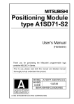
Positioningmodule
(AlSD71 -S7)
A
I
'
U
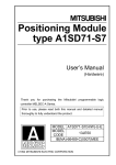
This manual covers this range.
I
--
t
I
Drive unit
motor
Pulse motor
Stepping motor
Etc.
%NO
I
I
1
The respective drive unit
manuals give details.
L-
-----
L
i
I
Fig. 2.1 OverallConfiguration
2-1
I
a
0-
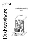
2. SYSTEM CONFIGURATION
MLSEC-A
AD71 TU
,u
AGGPP
.
a
L
SWOGP-AD71P
=
,-
AGPHP
2-2
Cable
(AC1OMD)
General-purpose
CRT
Cable
(AC30R2)
Printer
2. SYSTEM CONFIGURATION
2.2
,
ApplicableSystems
!
(1) The AlSD71 is only applicable to an AISCPU module.
(2) The number of A1 SD71 used with an A1 SCPU module must be within the
range of the number of I/O points of the AlSCPU.
(3) The AlSD71 can be installed in any two-slot area of a base unit, but the
following must always be considered:
(a) If possible, avoid installing the AlSD71 in an extension base unit
(A1 S52B,AIS55B,AlS588)
not equipped witha power supply
module, since the power supply capacity may be insufficient.
(b) If it is necessary to install the AlSD71 in an extension base unit
which does not have a power supply module, select a power supply
module, main and extension base units, and extension cables taking
into consideration (a) the power supply capacity of the main base
unit, and (b) the voltage drop across the main and extension base
units and extension cables.
,
-1
' i
(See the A I SCPU User's Manual for details.)
c
2-3
2. SYSTEM CONFIGURATION
2.3
MELSEGA
Programming
Equipment
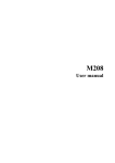
The following table indicates the equipment available for programming the
A1 SD71.
Table 2.1 Programming Equipment
Unit Division
DescriDtion
Software
package
Romarks
SWOGP-AD71P AD71(Sl)/AD72/AlSD71 (S[
I)
software package
Consists of the following:
Remarks
TVDe
~
~
~~~~~
~
~~
~~
Programming unit with CRT
Equipped with AOM writer, FDD and printer
interface functions.
AGGPPE
Intelligent GPP AGGPPE-SET
~
SW[ ]GP-GPPA
SWI IGP-GPPK
A series system disk
SWO-GPPU
User disk (3.5 inch, formatted)
AC30R4
Cable for connecting AlSD71 and AGGPPE.
K series svstem disk
Consists of the followina:
I
'rogramming
)nit
Type
I
AGPHPE
Plasma handy
programmer
AGPHPE-SET
1
User disk
RS-422 cable
Composite
video cable
Cleaning disk
Printer
SWO-GPPU
SWOS-USER
AC30R4
AC300R4
AClOMD
SWO-FDC
KGPR(S1)
KGPR-K
K7PR(S1)
Remarks
Programming unit with plasma display
Equipped with FDD, printer interface and
memory cassette functions.
SWI IGP-GPPA
A series svstem disk
SW[ ]GP-GPPK
SWO-GPPU
User disk (3.5 inch. formatted)
AC30R4
2DD
3Hn
I
K series system disk
I
Cable for connecting AlSD71 and AGPHPE.
3 m (9.84 ftl lenath.
Floppy disk ofr storing user programs (3.5 inch, formatted)
Cable for connecting CPU and AGGPPE. 3 m (9.84 ft) length.
Cable for connecting CPU and AGGPPE. 30 m (98.4 ft) length.
Cable for connecting GPP screen monitor display. 1 rn (3.28 ft)
lenath
Floppy disk for cleaning floppy disk drive.
For print out of program ladder diagrams and lists.
A7PR
A7NPR
Jrinter
RS-232C cable AC30R2
Printer paper
KGPR-Y
Cable for connecting AGGPPE and printer (KGPR(Sl), KGPR-K,
K7PR(S1), A7PR, A7NPR, general-purpose printer with RS-232C
interface). 3 m (9.84 It) length.
Paper for KGPR and KGPR-K printer. 9 inch. Available in units of
2000 DCS.
KGPR (K) ink
ribbon
KGPR -K-SI
ink ribbon
KGPR-R
Replacement ink ribbon for KGPR and KGPR-K.
KGPR-K-SI
Replacement ink ribbon for KGPR -K-SI
Teachina unit
AD71 TU
AD71(S1)/AD72/Al SD71 teach box.
2-4
1
3. SPECIFICATIONS
3.
SPECIFICATIONS
81
General Specifications
=MELs€GA
A
Table 3.1 General Specifications
t
Specifications
Item
Operating ambieni
0 to 55 "C
temperature
Storageambieni
temperature
-20 to 75 "C
Operating ambienl
humidity
10 to 90 %RH, non-condensing
Storagearnbieni
humidity
10 to 90 %RH, non-condensing
1 1
Frequency Acceleration Amplitude
Vibration
resistance
Conforms
to
'JISCO911
i(O.00;
0.075 inch)l
mm
10 to 55 Hz
I
55 to 150 Hz
I
Sweep Count
9.8 m/s2
I
10 times
'*(l octavelminute)
I
Shock resistance
Conforms to 'JIS C 0912 (98 m/s2(10 g) x 3 times in 3 directions)
Noise durability
By noise simulator of 1500 Vpp noise voltage, 1 ps noise width and 25
to 60 Hz noise frequency
Dielectric
withstand voltage
500 V AC for 1 minute across DC external terminals and ground
1500 V DC for 1 minute across AC external terminals and ground
Insulation
resistance
5 Mn or larger by 500 V DC insulation resistance tester across AC
external terminals and ground
Grounding
Class 3 grounding : If appropriate grounding is not available, connect
the grounding wire to the electric panel.
Operating
ambience
Free of corrosive gases. Dust should he minimal.
Cooling method
Self-cooling
'JIS :Japanese Industrial Standard
One octave marked ** indicates a change from the initial frequency to double or half frequency.
For example, any of the changes from 10 Hz to 20 Hz, from 20 Hz to 40 Hz, from 40 Hz to 20
Hz, and 20 Hz to 10 Hz are referred to as one octave.
3-1
3. SPECIFICATIONS
3.2
3.2.1
"ELECIA
PerformanceSpecificationsandFunctions
Pwbrmance specificatkns
Table 3.2 Performance Specifications
P.rCormancoa and Specifications
Item
48 points' (number of occupied slots : 2)
Number of I/O mints
I Number of control axes
I 2 (simultaneous or independent)
Linear interpolation (for simultaneous 2 axes)
Interpolation
Positioning
data
400 points per axis
Capacity
Setting m
Input from peripheral device or sequence program
15 minutes without battery (25 "C)
Lithium battery guarantees power failure backup for a total of
300 days. Battery guaranteed for five years.
RAM memory backup
-Method
Absolure and/or incremental method
1 to 16,252,928 (PULSE)
Max. 162 (m)
(command unit: 0.1 to 10 pn/PLS)
Max. 16200 (inch)
(command unit: 1 x lo-' to 0.001 inch/PLS)
Max. 16200 (degree)
(command unit: 1 x lo-' to 0.001 degree/PLS)
Positioning units
-
10 to
10 to
1 to
1 to
Position 1Positioning speed
ing
-
Acceleration and
Automatic trapezoidal acceleration and deceleration
Acceleration and
64 to 4999 (msec)
IBacklash
0 to 65535 x position command unit
(0 to 255 pulses i f unit is PULSE)
1
-
Ideceleration
I
-Ideceleration times
-:ompensation
IError cornpensatlon
The AlSD71 may be calibrated to allow for mechanical
errors in the positioning control mode and speed/positioning
control switching mode.
With zero address change function.
Zero return direction and speed depend on setting.
Zero return
I Jog operation
function
I Jog operation by jog start signal input.
Inching function
Operation using manual pulse generator.
M function
M code output
I Internalcurrent
I
200000 (PLSsec) (command unit: 10 PLS/sec)
120000 (mmlmin) (command unit: 10 mm/min)
12000 (incwmin) (command unit: 1 inchlmin)
12000 (degreelmin) (command unit: 1 degredmin)
consumption
External supply voltage,
current
Size mm (inch)
I 5 V DC, 0.8 A
1
4.75 to 26.4 V, max. 50 mA
130(H) x 69.5(W) x 93.6(D) (5.12 x 2.74 x 3.69)
0.38(0.84)
Weight kg (Ib)
* I/O allocation for the 2 slots are as follows:
First half slot ........Empty slot: 16 points
Second half slot Special-function module: 32 points
Section 6.1.1 gives details about the first half slot.
...
3-2
3. SPECIFICATIONS
,- .
c
3.2.2
.I._
KLSEGA
.,
Functions
The A I SD71 has functions used for positioning and positioning control during
two-axis independent operations and two-axis linear interpolation operations.
These functions are utilizedas follows:
*
By test operation of a peripheral
device or teaching unit
f
A peripheraldevice or AD71TU is
connected to A1
an
SD71, and positioning is executed using the peripheral device or AD71TU.
This is used during program checks
or
test operations.
By a sequence program ..-.......-........
Positioning is executed using a program built in the PC CPU.
!
!
For use of the peripheral device, refer to the SWOGP-AD71POperating
Manual.
Manual. For use of the AD71TU, refer to'the AD71TU Operating
Positioning control functions are shown below.
Sequence Program or AGGPP
Function
I
I
i
Two-axis interpolation
operation
Error detection
An error code is provided by the AlSD71 i f a data setting
or positioning control error
(For details of the error codes, refer to Chapter 8 . )
Set data read and write
A1 SD71 set data (parameters, zero return data,
positioning data) can be read and written.
Present value and speed
read
Present value data and speed data can be read from the
A1 SD71.
(Present value can be read and monitored during
positioning.)
Teaching
(positioning data write)
After manual positioning, present value can be written as
positiondata.
(Data is written to both axes in the case of two-axes
interpolation operations.)
I
~
Two-axis independent
operation
/
C
L
r
?
/
occurs.
The positioning functions of the AlSD71 are shown in Table 3.3.
3-3
,
-
4
3. SPECIFICATIONS
MLSEGA
Table 3.3 AlSD71 Positioning Fumctions
Method with a eoquenm program or mrthod(tat operation)
ublng a pwlpborel device (or AD71TU)
Independent operation
Functiona
~
~
~~
Inching operation function
JOQ operation
function
Two-axee interpolation operation Two-rxae
The driw for the given &is is advanced by
a predefined number d puher uoh tim L
rewived. Themanual
Unavailablemanualpulseis
pulse isprovidedby
the manualpulse
generator.
'
Zero return
JOG operations can k done when a JOG
-on
commandfrom the PCCPU (or Unavailable
pmpheral device) ia turned ON.
Returns byazero return start commandfrom
thePCCPU
(orperipheraldevice).
The Unavai'able
current value is corrected to the zwo
addresa after zero returnis compbted.
One-time
positioning
Positioning ia executed at a s p e d with two
Positioning is executed at a set spwd from axes moving in I i n w directionsfromthe
the current position to the setting position. current positionto the setting position (linear
interpolation).
n-timer
positioning
Changer speod in accordance withthe Podtioning by linearinterpolationcan be
positioningdataset by a one-time start executed Qontinuousiy
M well am with the
siclnal. and execute8 positioning.
two-axis independent operation.
Positioningaccompanied
by a changeinapeed
(pattern c h a n g e )
Changeaspeed in accordancewith the
positioningdata aetby a one-tim. atart Unavailable
signal, and executes positioning.
Error compensation and backlash compensation functions are valid for
all the functions shown in Table 3.3.
I f positioning is done using a sequence program , a PC CPU can output
the set M code from anA1 SD71 whenpositioning starts or after positioningis completed. (Peripheral devices donot output M codesduring
positioning.)
Current values inan A1 SD71 can be changed (rewritten) by a sequence
program or peripheral device before positioning is started.
Positioning can be done continuously by setting a positioning start data
number to 20 points in the buffer memory (X axis: 0 to 39, Y axis: 300 to
339) in an AlSD71 before positioning starts in the postion controlmode.
3-4
3. SPECIFICATIONS
. i.
3.3
General Description .of Positionin0 system Operations
This section. givesageneral
positioning system.
3.3.1
description of the AlSD71 and its useina
Positioning system using an AiSD71
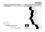
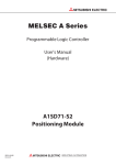
Fig, 3.1 shows the operationof an AlSD71 in aposaioning system.
Positioning
module
A1SD71 Forward pulse
‘
string
CPU
PC
(A1SCPU)
-LnnT
-c
I
Program-
d8
‘5
-----
c
Set
data
i
Error
counter
-
Reverse
pulse
string
Dive unit
mand
Interface
Feedback pulse
--------Peripheral device,
AD71TU
Servo motor speed
Fig. 3.1 Positioning System Operation Block Diagram
The AlSD7l’s output is a pulse string
When pulse strings are output, pulses are converted into error counters.
Deviation counter pulse values are converted into DC analog voltages by a
D-A converter, and changed into speed commands.
The drive unit gives a speed command.
The motor begins to rotate and the pulse generator
PG gives feedback pulses
in proportion to the revolutions of the motor to subtract accumulated pulses.
The motor rotation continues maintaining the constant deviation counter pulse
value.
When the command pulse output from the AlSD71 ceases, the deviation
counter pulse value decreases,and the speed slows down.
Then, when the deviation counter pulse value becomes0, the motor stops.
Thus, the motor’s rotary speed is proportional to the frequency of the command pulse, and degree of the angleof the motor’s rotation is proportional to
the number of command pulse output pulses.
Therefore, transmission can be done to a position that is proportional to the
number of pulses of a pulse string by specifying the feedrate per pulse.
The pulse frequency is equal to the number of revolutions (transmission
speed) of the motor.
3-5
3. SPECIFICATIONS
MELSEGA
General designof positioning system
V
W
Servo motor
PO
A
Vs
n
L
R
V
N
K
e
PO
P
(1)
: Position detection increment (mm/p)
: Command pulse frequency (p/s)
: Number of pulse generator slits (slits/rev)
: Feed screw lead (rrtmhev)
: Reduction ratio
: Moving part speed (mm/s)
: Motorspeed(rpm)
: Position loopgain (set-'1
: Deviationcounterpulsevalue
: Zero point (pulse)
: Address (pulse)
Position detection increment
A=R x n (mWP)
(2) Command pulse frequency
V
v s = (P/S)
x
(3) Deviation counter pulse value
vs
E = -(pulsg
K
Expression (1) indicates the travel per pulse, i.e. the number of output pulses
x A. Using expression (2), calculate the command pulse frequency from the
work speed and position detection increment. Expression (3) indicates the
relation between thecommand pulse frequency and deviation counter pulse
value.
Any of the four positioning units, (mm), (inch), (degree), and (PULSE), may
be selected individually for the X and Y axes.
According to the target positioning address,apulse string is output, and
positioning is executed by the AlSD71 by setting data such as the travel
distance and acceleration/deceleration time per pulse, the positioningspeed,
and the positioning address in a positioning command unit.
3-6
3. SPECIFICATIONS
,.
.
I
I. . . -
..
3.3.2
Signal communications betwwn an AlSD71 and each unit
Fig. 3.2 shows a function block diagram for signal communications between
each unit conneoted to an AlSD71, an A1 SCPU, peripheral device, and the
drive unit.
0 Communicqtion between PC CPU and AlSD71
Control signals and data communications via base unit, they consist of:
Control signals.....I/O signals given in Section 3.6.
Data..................... Written to and read from the buffer memory by the PC
CPU. Detailed in Section 3.5.
Communication between peripheral device (or AD71TU) and AlSD71
Data write, 'A1SD71 test, A1 SDM monitor, etc. via the A1 SD71's RS-422
connector.
Communications between drive unit and AlSD71
Control signal communication to and from the drive unit and pulse train
output from the AlSD71. (For the I/O interface, refer to Section 3.7.)
c
AlSD71
:I-
Yzo. Y21, Y22
I
II
I
- ll
StUl
II
I1
I
Manu4 pllu g m r a b r A p h u o
Manud p
u
l
ugnuatof B phue
L
-2
Fig. 3.2 AlSD71 Function Block Diagram
3-7
Drive unit
Manual
Pulse
Generator
U
3. SPECIFICATIONS
MELSEGA
AlSD71 operation description
3.3.3
I
Fig. 3.2 PC tnitiated Positioning Procedure
I
START
1
Yes
AlSD71 buffer memory all clear
1
. . . . . . . . See section 3.4.1.
Set parameters
I
. . . . . . . . Clear the A1SD71 buffer memory using the peripheral device.
1
Set zero returndata
1
Setpositioning data
. . . . . . . ..See section 3.4.2.
Although data may be set by the sequence
program, it isrecommended to. set the’ data
(especially parameters and zero point return
data) using the peripheral device or AD71TU.
. . . . . . .. See section 3.4.3.
I
1 Yes
Zero return start signal(Y23, Y24)
ON
Yes
.. Write start data numbers into X-axis addresses 0 and
addresses 300.
Y-axis
(X12, X13 ON?)
‘
Next position required.
r
END
e
I
(1) Section 6 gives details about zero return start and positioning start conditions.
(2) Table 3.4 shows the data needed for control signals (positioning functions)
from the PC CPU.
3-8
3. SPECIFICATIONS
-WkS€GA
Table 3.4 Data Needed for PositiOnhg Functions
Data
setting
I
Unit
Speed limit value
speed
Jog
value
~~
0
300
I
~
I
I
Starting bias speed
Backlash compensation
Upper stroke limit
'arameter
Lower stroke limit
_
_
_
_
~
~
~
0
I
I
I
Error compensation
I
control
1
0
0
0
0
0
I
0
I
0
0
I
I
I
1
0
Acceleration arid
deceleration times
setting
direction
Rotation
method
Positioning
M code ONOFF timing
0
0
0
0
0
0
I
I
0
0
I
I
0
0
I
I
0
0
I
I
0
0
0
0
Travel per manual pulse
generator during inching
0
Zero return direction
0
0
0
Zero return method
!ero
eturn data
0
0
Positioning complete
signal output time
Pulse output mode
0
0
I
0
0
Positioning
0
0
0
I
Zero
return
operation
0
Travel per pulse
limit
Manual pulse
ganerator
operation
0
0
Zero return address
0
0
0
0
0
Zero return speed
~~
Zero return creep speed
0
Zero return dwell time
0
Torque limit
0
Positioning information
speed
Jositioning
jata
Positioning
I
I
0
Positioning address
0
Dwell time
0
Start data number area
I
I
I
Speed change data
Ithers
I
I
0
0'
Jog speed
0'
I
0
0
'
0
Inching operation enable
0
Inching operation speed
0
Indicates functions used to change the speed during A I SD71 positioning.
3-9
3. SPECIFICATIONS
3.4
MEL!SEGA
Types and Functions of Setting Data
Setting data is data that is necessary for an AlSD71 to do positioning
control. Setting data is thegeneral termfor the following three kindsof data:
Section 3.5 gives details about storing set data in the buffer memory.
Parameter
Setting data
Zero return data
Positioning data
Setting data is written using the following two methods:
0
t
1) By a peripheral device
AD71TU
or
2) By a sequence program
.......
.......
The Operating Manual and the AD7lTU
Operating
Manual
SWOGP-AD71P give
details.
Section 6 gives details.
It is necessary to set data for two (X and Y) axes.
POINTS
I
(1) All-clear data
Before writing setting data, use a peripheral device to do allclear
processing of the memory.
(2) Data setting when using either the X or Y axis
When using either the X or Y axis, write parameter and zeroreturn
data to the axis not used.
Writing data must be a value in the setting range given in the
User's Manual. However, even if an initial value (default value)
isby
set parameter,
a there
is no problem.
If zero return is done without writing data, an error occurs, and the
error detection signal (XlB) goes ON.
1
3.4.1
Parameters
Parameters are the basic data which enable the AlSD71 to do positioning
control. The data in Table 3.5 is contained in parameters.
Initialization of parameters
If all parametersare not setor an error outside thesetting range is detected
by parameterchecking,the AlSD71 will becontrolledusingtheinitial
values shown in Table 3.5.
However, parameterarea data remains as user-set values.
Parameters are checked when:
3-10
3. SPECIFICATIONS
, .
. ;
-
1) The power
2)
is turned ON;
Parameters are sent from a peripheral device to an AlSD71;
3) A PC CPU ready signal from the PC CPU to the A1SD71 switches from
OFF to ON;
4)
(1) zero return, (2) positioning, (3) jog operation, or (4) inching has been
selected in theperipheral device or the AD71TU.
However, error code and error detection signals are not given for 1) above
(power ON parameter check).
Table 3.5 Parameter Settings
decaleration times
Positioning complete
1 2 signal output time
,4
Direction setling
I5 Positioning
method
M +e ONlOFF
tmng
to 20000(msec)
0: Currentvalueincreasewhenforward
puke is output
1: Currant value incra.de when reverse pulw is wtpul
0: Absolute
1: lnuernental
2: Inuernental/akolute combined
0: M code not used
1 : M code used
msec
300
0: WITH mode
1 : AFTER mode
':Not fixed when shipped from the factory. All clear set to 0 .
3-11
l
0-absolute
l
-
3. SPECIFICATIONS
M t W A
The actual parameter speed limit values and JOG speed limit values in Table
3.5 are multiplied by 6.1 (PLSIsec).
For example, the value that is nearest to 200 (PLS/sec) is multiplied by 6.1
(PLSkec), even if the speed limit value is set to 200 (PLSkec).
200 + 6.1 = 32.78688.....(Decimal point values are rounded off.)
The actual speed is 6.1 x 32 = 195.2 (PLSIsec).
Numbers 2 to 12 show the setting range when settingwitha
sequence program.
However, parameters whose unit is x10-l or x10' are processed
automatically as x10-l or x1 O1 in the A1 SD71when processed with
a value set in the program.
(Example) If the speed limit value is set to 200, the value becomes
2000x10' = 20000 mm/min in the AlSD71.
Parameter data is explained as follows.
(1) Unit
Selects the units(mm, inch, degree, or pulse) for positioning control.Can
be set independently for X and Y axes (e:g. X axis = mm, Y axis =degree).
(2) Trav.el per pulse
0 Specifies the traveldistance per pulse as determined by the mechanics
of the system.
Controls the number of pulses contained in the pulse train from the
A1 SD71.
.
.
(3) Speed limit value
Specifies the maximum speed for positioning (or zero return).
When the positioning speed called at a given time is greater than the
speed limit value, the speed is limited to the value set by the parameter.
When a new speed is called during positioning by the sequence program and this is greater than the speed limit value, the speed is limited
to the value set by the parameter.
(4) Jog speed limit value
Specifies the maximum speed for jog operation.
The jog speed limit value must be within the range shown in Table 3.5
and must not exceed the speed limit value.
When the jog speedset using the peripheral device or sequence
program is greater than the jog speed limit value, the jog speed is kept
to the limit value.
For jog operation, refer to Section 6.3.4.
3-12
0
A minimum starting speed is required for the smooth operationof some
motors fe.g. stepping motors). This m,aybe set as a starting bias speed.
Th6 starting bias speed is used for positioning, jog operation, and zero
return. See fig. 3.3.
f
speed
Positionina swed
Jog operason speed
Zero return speed
Starting
-: Speed if starting bias speed has
been set
t
- - - : Acceleration and deceleration
speeds if starting bias speed =O
Ftg. 3.3 Speed Change When Starting Bias Speed Is Set
For positioning with interpolation between axes, the starting bias speed set
for the axis with the shorter distance to travel is ignored.
(6) Backlash Compensation
0 Allows a backlash
compensation (see Fig, 3.4) to be programmed in for
accurate positioning. Note that there is also an error compensation
facility to allow for tolerances within the mechanical drive, see note
(9).
When backlash compensation is set, every time the travel direction
changes during positioning, a feed pulse occurs which exceeds the
backlash compensation amount.
During manual pulse generator inching, the pulse output begins as
soon as the number of input pulses exceeds the backlash compensation amounteach timethe direction of movement changes. (If the
inched distance is less than the backlash compensation, feed pulses
will not be generated. However, the AlSD71 does calculate the subsequent positions according to the updated data).
0
The feed pulsefor a backlash compensation
amount is generated byat
least one JOG start signal during the JOG operation. Therefore, even
if the travel distance is smaller than a backlash compensation
amount,
the feed pulse for a backlash compensationamount occurs.
A
3-13
3. SPECIFICATIONS
r
0
-
MELSEGA
Backlash compensation is valid after zero return. After redefining the
backlash compensation, always zero the system.
-
zero return direction
Lead screw
Work
Backlash compensation actual value
Fig. 3.4 Backlash Compensation
0
For the backlash compensation amount, the range of the number of
outputpulses differs in accordance with the unit to be set in the
parameter.
I
Setting Units
Number of Output Pulses
PLS
0 to 255
mm
’0 to 65535
Inch
The symbol indicates the value when the travel distance per pulse is
set to 1.
(7) Upper stroke limit
0 Defines the upper limit value of machine travel.
0
The stroke limit is checked before each positioning operation and if
outside the allowed range, positioning is halted.
Duringjogoperation andmanual pulser inching, thestroke limit is
ignored.
( 8 ) Lower stroke limit
0 Defines the lower limit value of machine travel.
The stroke limit is checked before each positioning operation and if
outside the allowed range, positioning is halted.
During jog operationand manual pulser inching, thestrokelimitis
ignored.
(9) Error compensatlon
When the set value andan actual feedrate differ, this is called error
compensation.
When the unit is mm, an error compensation per m(per 100 inches if the
unit is inchesand per 100 degrees if the unit is degrees) is set to 0, and
the feedrate of any set value is transmitted. (Automatic start) Then, the
actual feedrate (A) is measured, andthe error compensation amount and
backlash compensationamount are calculated as indicated below.
When the unit is mm
Error compensation amount (1 O-’pm) =
When the unit is inches
Error compensation amount (1
3-14
inch) = Setvalue(inch1-
1),
07
3. SPECIFICATIONS
When a unit is degrees
Error compensation amount (1
degree)
Set value(degree) - I
j X
07
Set the numerical value calculated in the following expression as the
backlash compensation amount when there is a machine error.
Backlashcompensation= Backlash compensationactual value x Set value
A
(10) Manual pulser inching travel increment
Defines .the distance travelled each timeamanualpulser
inching
command is given.
The AlSD71 counts the number of manual pulse inching command
inputs and transmits the appropriate number of output pulses. (The
applicable outputspeed range is 10 to 20000 PLS(unit = 10 PLS/sec.).
See section 3.5.
(11) Acceleration and deceleration times
Defines the period of time from the start of positioning to when the
speed limit value specified in the parameter is reached. (Referto Fig,
3.5.)
Parameter speed limit value
-: Speed ifstarting
Positioning
speed
been set
bias speed has
- - - : Acceleration and deceleration
Time
bias speed
Actual
1
speeds if starting bias speed
E
0
Actual
deceleration
time acceleration
time
Set acceleration time
Set deceleration
time
Fig. 3.5 Acceleration and Deceleration Times
The acceleration time is the same as the deceleration time.
They cannot be set differently.
The acceleration and deceleration are controlled at a constant value.
When the positioning speed is lower than the parameter speed limit,
the acceleration and deceleration times are comparativelyahort.
Therefore, themaximum positioning speed must be either equal to the
parameter speed limit or an approximate value.
The acceleration and decelerationtimesarevalid
for zero return,
positioning, and jog operations.
For interpolation positioning, the acceleration and deceleration times
for a master axis are valid. (The acceleration ane deceleration times
for a slave axis are ignored.)
(12) Positioning complete signal duration
Sets the duration of the "positioning complete signal" from the AlSD71.
Positioning is considered to be complete after the AlSD71 terminates
pulse output and the predetermined dwell time has elapsed.
3-15
/'
e
3. SPECIFICATIONS
MLSEGA
(13) Pulse output mode
I
Defines the outputmode as A type or B type.
Forward pulse or reverse pulse, two pulse chains.
4
Forwardfeed pulse
mI3E-F
I Fomard and reverse feed wlses. Travel direction
controlled by direction sign (SER).
is
4
Feed pulse
ml3E
+ direction
travel
25 ms
- direction
travel
B
type
Low in forward direction.
High in reverse direction.
(Present value increases in forward direction and
decreases in reverse.)
Direction setting
Selects the direction for which the present value increases. (Set 0 when
using forward pulse output. Set 1 when using reverse pulse output.)
Positioning and zero return follow this direction of rotation.
Positioning mode
Specifies incremental, absolute, or incrementaVabsolute combination
modes for positioning.
In incremental mode positioning, positions are reached with reference
to the previous position. (See Fig. 3.6.)
A
Zero point
B
-
Movement from A to B.
H
0
Travel
Fig. 3.6 Incremental Method
In absolute mode positioning, positions are reached with reference to
a Zero point address. (See Fig. 3.7.)
Zero point
0
A
-
Address 70
-B
Address 100
To move from B to A,
address specify
70 as
the destination address
Fig. 3.7 Absolute Method
3 - 16
3. SPECIFICATIONS
To use both incremental and absolutemodes in the same axis (e.g. X
axis), set 2. In this cqse, the mode is controlled by the individual piece
of positioning data. (Refer to Section 3.4.3.)
(16) M code ON/OFF timing
M codes are code numbers (1 to 255) assigned by the user to control
auxiliary functions (for example, clamp,drill rotation, stop, and tool
exchange commands, etc. ) at defined points in the positioning cycle.
These are used by the PC CPU to co-ordinate the operation of external
equipment and processes.
M code use/non-usemust be specified as well as where in the positioning sequence they are to be used.
When M code non-useis specified or peripheral devicetest mode is in
operation, M code datain the buffer memory is clearedand the"M code
ON" signal is not output.
When the M code used isspecified, the output timingof the M code ON
signal must be specified.
"M code ON"signal output is available in two timing modes, WITH and
AFTER.
(a) WITH mode
The "M code ON" signal is given at approximately the same time as
the positioning operation starts.
ttern 01
Pattern (
I
I
M code OFF
I
P
Fig. 3.8 WITH Mode Signal Timing
(b) AFTER mode
The "M code ON"signal is given after the positioning operation has
finished. In this mode, if the operation is stopped before it is complete the "M code ON" signal is not given.
3- 17
3. SPECIFICATIONS
MELSBA
Start
Operation
M code
BUSY
M code ON
.M code OFF
I
I
Fig. 3.9 AFTER Mode Signal Timing
POINTS
0
I
The "M code ON" signalis not given if the M codedata in the
positioning data is set at 0.
The M code is ignored if the positioning pattern is "11" and the "M
code ON" signal is not given. (For details of the positioning pattern,
refer to Section3.4.3.)
The next positioning operation is not started until the "M code ON"
signal is switched off. An error condition arises if the "M code ON"
signal ison at the riseof the start signal and positioning isnot started.
The "M code ON" signal is turned off when:
1. "M code OFF" signal changes from OFF to ON;
2. PC ready signal (Y2D) is OFF; or
3. Zero return, positioning, jog operation, or inching
mode is selected
in the peripheral deviceor the AD71TU test mode.
3-18
3. SPECIFICATIONS
When positioning processing beginning with pattern 11 is executed, the M
code ON signal goes ON when positioning processing of pattern 00 or
pattern 01 begins in the WtTH mode or whencompleted in theAFTER mode.
The M code is set before pattern 11 positioning processing begins.
t
Start
I
I
I
M code set for pattern
00 is set at this point.
Pattern 1 1
/-\
Pattern 1 1
Pattern 00
I
I
I
\
I
M code
I
I /
I \
/
4
I
I I
BUSY
'M code ON'
(WITH mode)
I
I
I
I
I
I
'M mode ON'
(AFTER mode)
I
'M code OFF'
Fig. 3.10 "M Code O W Signal Timing for Positlohing Pattern "1 1''
Fig. 3.10 shows the M code OW signals In the WITH mode and the AFTER mode. However, this
is.only to explain the M code ON signal, and either (WITH mode or AFTER mode) can actually
be used.
3-19
3. SPECIFICATIONS
3.4.2
MELSEC-A
Zero return data
This defines ahome position or zero point for the A1 SD71. Refer to Table 3.6.
Zero return data is checked when:
1) Parameters or zero return data is transferred from the peripheral device
to the A I SD71:
2) "PC ready signal" output from the PCCPU to the AlSD71 changes from
OFF to ON; or
3) Zero return, positioning, jog operation, or manualpulserinching is selected in the peripheral device test mode.
Table 3.6 Zero Return Data
mm
inch
degree
PULSE
1
0 : Forward direction (address increases)
1 : Reverse direction (address decreases)
-.
0 : Pulse generator(PG)zero-point signal
1 : Stopper stop (1) and dwell timer time-out
2 : Stopper stop (2) and signal from drive unk
1 to12000
x 10'
1 to12000
mm/min
1
1 to12000 x10'
mm/min
to12000
'
gcnlchimin
1 to12000
;Aglmin
;Lhlmin 1 to12000 ;Aglmin
x1 0'
PLS/sec
to12000
1
x1 0'
PLSJsec
0 to 499(x101 msec)
I
10 to 250(%)
(1) No. 3 to No. 7 can be set by the sequence program.
(2) Setting numbers "0 and 1" of the zero return direction and setting
numbers "0,1 , and 2" of the zero return method are numbers set
by a peripheral device.
When setting No. 1 and No. 2 from the sequence program, refer to
Section 3.5.7.
The zero return speed and creep speed in Table 3.6 are multiplied by 6.1 (PLSlsec).
For example, the value that is nearest to 200 (PLSlsec) is multiplied by 6.1 (PLS/sec), even if
the speed limit value is set to 200 (PLSsec). (Decimal point values are rounded off.)
200 + 6.1 = 32.78688
The actual speed is 6.1 x 32 = 195.2 (PLSlsec)
....
3-20
3. SPECIFICATIONS
1
.,
,
.
,
Zero return data is explained below:
(1) Zero return direction
Specifies the direction for zero return.
Zero return is controlled according to the zero return direction and
speed. Deceleration is started when an actuator is operated. Always
ensure that the zero return direction is correct for thedrive system used.
I
I
(2) Zeroreturn methods
There are three kindsof zero return methods:
The pulse generator (PG) zero-phase signal method
Mechanical stop (1) (caused by dwelt timer time)
0 Mechanical stop (2) (caused by a signal from the drive unit)
,
(a) Method by the pulse generator(PG) zero-phase signal method
This method of stopping by a zero-phasesignal from the PG is shown
in Fig. 3.1 1.
A PG with a zero-phase signal is necessary. (Referto Fig. 3.12.)
Zero return speed
Deceleration by near-point dog ON
-74
Creep speed
with the drive)
dog OFF position is
near the center of the zero-phase signal HIGH.
If the near-point dog is turned ON when the zero-phase signal
is LOW, the zero return stop position causes an error equal to
one rotation of the servo motor.
\
Near-point dog
?/a-////IZ/////A
ON
OFF^
.I"
Zero-phase
signal
One ssrvo motor rotation
(one PG rotation)
Fig. 3.11 Zero Return Using a PC CPU Zero-Phase Signal
rn
t
One PO rotation
I
PG zero-phase signal
Fig. 3.12 Feedback Pulse Pattern
3-21
3. SPECIFICATIONS
MEt.3EEc-A
(b) Mechanical stop (1) (caused by a dwell time time-out)
After a near-point dog has operated and the dwell time has passed,
zero return is completed. (Refer to Fig. 3.13-1 .)
In this case, if the dwell time hasnot passed, even if the near-point
dog goes OFF halfway, zero return is not completed. After reaching
the creepspeed, limit the servo motor torque (Section3.4.2(7) gives
details).
If the servo motortorque isnot limited, the servo motormay malfunction when a stopper is hit.
After the dwell time times out,
the zero return complete signal
._
motor
time
Range in which the servo
is
rotation forcibly
stopped by the stopper
Dwell
count start
-
Zero return torque limit valid
Torque limit valid range
Fig. 3.13-1 Zero Return by Using Stopper Stop (1)
(c) Mechanical stop (2)(caused by an external stop command)
This is the method of stopping by inputting an external stop command when a servo motor interferes with the stopper. (Refer to Fig.
3.13-2.)
Forcibly input a zero-phasesignal (stop command) to the zero-phase
signal terminal by an external switch after the near-point dog goes
ON.
When inputting a zero-phase signal (stop command), the ON/OFF
state of the near-point dog is not a problem.
After reaching the creep
speed, limit the servo motor torque (Section
3.4.2 (7) gives details).
If the servo motortorque isnot limited, the servo motormay malfunction when a stopper is hit.
Zero return speed
Deceleration by near-point dog ON
Stop by stopper
,
-
-
:
I
Stop command to the zero-
/ phase signal terminal
Zero return torque limit valid
Torque limit valid range
I
piGK-1
Fig. 3.13-2 Zero Return Using a Stopper
If a stop signal is input before the speed decelerates to the creep speed, excessive power is
delivered to the servo motor and machine system, causing a fault.
3-22
3. SPECIFICATIONS
(3) Zero return address
This address is set as the present value of the home position upon
completion of zero return.
Set the zero return address to either the upper or lower stroke limit
set
in the parameters.
(4) Zero return speed
Sets the zero return speed. (Refer to Fig. 3.14.)
(5) Creepspeed
The creep speed is low-speed until stopped
after decelerating from the
zero return speed by the zero return point dog being ON during zero
return. (Refer to Fig. 3.14.)
The creep speed varies according to the detected error in the case of
zero return by a zero-phase signal and to the size of an impact during
collision in the caseof zero return by stopper.
Therefore, set the creep speed taking the error range and the size of
an impact into consideration.
Zero return speed starts deceleration.
Actuator signal
Creep speed
Drift (according to drive unit)
I
I
Zero-phase signal
Adjust the actuator so that its OFF
position is near the center of the
zero-phase signal.
Torque limit valid range
~~
Fig. 3.14 Zero Return and Creep Speeds
(6) Zero return dwell time
The zero return dwell time is the time until zero
return is completedafter
the near-point dog goes ON during zero return by stopper stop (1).
Set the time until stopping by the stopper after the zero return speed
decelerates to the creep speed.
Even if any value (in the setting range) is input at the time other than
stopper stop ( l ) , there is no problem.
3-23
3. SPECIFICATIONS
MELSEC-A
(7) Torque limit
This is the set value to limit the torque of a servo motor after reaching
the creep speed when doing a zero return.
POINTS
0
0
I
r--
I
A D-A converter is necessary for torque limit.
Be sure to set it when doing a zero return operation by stopper stop
(2)*
Even if any value (in the setting range) is input when torque is not
limited, there is no problem.
I
PC
Torque limit value
d
Pulse
Drive
unit
Operation
AlSCPU
converter unit
Output
by program
(Analog amount)
Fig. 3.15 Torque Limit Block Diagram
3-24
3.4.3
Positioning data
T
Positioning data is used in the A l S D 7 l to execute positioning control (Le.
control other than zeroreturn, inching and jog operation). Refer to Table 3.7.
Table 3.7 shows one block of positioning data. 400 blocks can beset for the
X and Y axes, respectively.
The block of data used for positioning is dictated by the number set in the
positioning start area of the buffer memory.
Positioning data is checked when positioning is started.
Table 3.7 Positioning Data List
1
Setting Data
bl5
b8b7
bO
1111711117717
00 : Positioning terminated
01 : Positioning continued
11 : Speed changed and positioning then continued
1
[Positioning method
0 : Absdute
1 : Incremental
Valid only when incrementaVabsoiute combination is
specified i n parameter.
'ositioning
nformation
-
Positionin direction (valid in incremental mode only)
0 : Forward direction (address increase)
1 : Reverse direction (address decrease)
L
Unused (may be 0 or 1)
.
M code (0to 255)
Set M code = 0 when M code is not specified
mm
2
'ositioning speed
3
'ositioning
rddress
-
4
hell time
-
1 to
mmlmin
12000
x10'
I
inch
1 to
12000
x1
inch/min
I
degree
1 to
12000
x1
deg/min
I
PULS
1 to
20000
x101
PLSsec
0 to 499(x10' msec)
I POINT 1
No. 2 to No. 4 can be set from the sequence program.
3 -25
I
3. SPECIFICATIONS
The data to be set as positioning data is explained below.
(1) Positioning information
Separate the information for the X and Y axes.
Positioning information consists of 16 bits and includes the following.
b8b7
b15
bO
Positioning pattern
Positioning method
-
Positioning direction
Unused
M code
(a) Positioning pattern
Specifies positioning completion in accordancewith the positioning
data that corresponds'to the data
number or positioning continuation
by the next data number by using the positioning pattern.
The positioning continuation pattern is as follows:
1) Positioning iscompletedinaccordance
with the specified address, and positioning iscontinued by the next data number
(positioning address).
2) Positioning is continued after changing speed at the specified
address.
Fig. 3.16 shows howto specify bits in the
buffer memory to specify
the positioning pattern.
This pattern data is specified by the first two bits of the positioning
information.
Bit 1
Bit 0
I
Positioning pattern
00 : Positioning end
01 : Positioning continued (in any direction)
1 1 : Speed changed and positioning then continued
(in the same direction)
10 : No setting
Fig. 3.16 Positioning Pattern
3-26
0
Positioning end
Drives to the specified address, positioning is complete after the dwell time
has elapsed.
Start (Y20)
Positioning commenced (X
BUSY (X14)
I
!
I
I
I
I
I
Speed graph
H
For pattern 00
Dwell
Fig. 3.17 Pattern 00
0
Positioning continued
The positions are reached consecutively
in the orderspecified by their data
numbersby a single startsignal. (The BUSY signal remainsonduring
positioning.)
Start(Y20)
Positioning commenced(Xl8)
yzt,j
I
BUSY(X14)
I
I
I
i
Speed graph
-
P = address
]
[;=speed
dwell time
POINT
H
Dwell
b
tl
Pattern 01
v2
+!
H
Dwell
Dwell
t2
&
I
t3
Pattern 00
4
1
Pattern 00 should be set for the last position in a series of continuous operations.
Pattern 01 may be set for interpolation positioning. In this case, the
patterns for the X and Y axes should be the same. The X and Y axis
patterns are checked before operation and any error will stop positioning.
3 -27
3. SPECIFICATIONS
MELSEC-A
Positioning continues with speed change
The positions are reached consecutively
in the order specified by
their data
numbers by a single start signal. During positioning, the speed may be
changed but the direction remains the same. (Refer to Fig. 3.19.)
commenced (X18
I
I
I
I
!
I
M code
I
I
P = address (pulse)
V = speed (P/S)
t = dwell (in 0.01 second increments)
Table 3.8 shows the positioning data for Fig. 3.19. The following conditions
apply:
M code ON/OFF timing
: AFTER mode
Incremental/absolute method : Incremental and absolute combined
Table 3.8 Positioning Data
107
108
In the method column, Abs. indicates absolute
method and Inc. incremental method.
3-28
3. SPECIFICATIONS
. ._.
'
'
,'
..I
:
..'
'
I
POINTS
1
(1) For continuo'us positioning, pattern 11 should not be used more
than nine times consecutively. M e r e a large number of consecutive 11 patterns are being used, they must bebrokendown by
placing 01 pattern data every nine 11patterns. (e.g. pattern 11 = 9
times, pattern 01 = 1 time, pattern 11 = 9 times, pattern 00 = 1 time).
(2) Always set pattern-00 inthe final datablock.
(3) While pattern 11 is continuing, the direction of movement and the
positioning method should remain unchanged, onlyafter pattern 01
or 00 may these be changed. If the speed is changed after deceleration has started, the new speed is ignored and, if the M code
has been set in WITH mode, the "M code ON" signal is not given.
(4) During positioning using pattern 11, dwell time data andM code will
be ignored.
(5) Interpolation positioning cannot be specified when pattern 11 is
being used.
(b) Positioning methods
The positioning method specified in positioning data becomes valid
only when a parameter positioning method wasspecified to use both
incremental and absolute mode positioning.
(If the parameter positioning method is not specified to use both
incremental and absolute mode positioning, the specification of the
positioning method in positioning data is ignored, and the positioning
method follows the setting in the parameter.)
POINT
I
While pattern 11 is oontinuous, positioning methods cannot be
changed.
When use of both incremental and absolute mode positioning is
spedified, positioning methods can be changed after pattern 00 or
pattern 01.
.
(c) Positioning direction
For incremental mode positioning, the direction of travel relative to
theprevious addressmust be specified. (0 specifies forward,
increasing address numbers and 1 specifies reverse, decreasing
address numbers.)
In absolute mode, the positioning direction is ignored.
(d) M code
Specifies an "M" code relevant to that position address. (range:0 to
255)
The code should be set to 0 if it is not required.
During interpolation positioning, M codes are given individually for
the X and Y axes. (X-axis M code, buffer address = 46. Y-axis M
code, buffer address = 346.)
3-29
3. SPECIFICATIONS
MELSGA
I ’
(2) Positioning speed
Specifies the speedat which the next position is to be approached.
POINTS
I
(1) Before operation, the parameter speed limit is checked and if the
positioning speed exceeds the speed limit value, the parameter
speed limit value is used.
(2) In the case of linear interpolation, the setting speed of the axis
whose travel distance is smaller is ignored.
Therefore, when thecombination of traveldistanceandspeed
differs greatly between the X and
Y axes, the travel speed
of either
X orY may be larger than thesetting speed. (The speedlimit value
is ignored.)
In the same case of linear interpolation, Mitsubishi recommends
setting the same speed and speed limit value to both the X and Y
axes.
Positioning speed for linear interpolation
During linear interpolation positioning, the speed set for the axis with the
furthest to travel takes precedence and the speed of the other axis is derived
as follows.
(Short travel axis speed)
-
= (long travel axis speed) x ( short trave’ distance)
( long travel distance)
An example of this is given in Fig. 3.20 which uses the following data:
Parameter set value
X Axis
: speed limit value
~~
~
~~
~
Positioning data set value : positioning speed
Y Axis
20 KPLSlsec
~
~~
~~
~
20 KPLSlsec
50 KPLSlsec
~~
50 KPLSlsec
To move from point A (address 0, 0) to point B (100 kp, 200 kp), X-axis travel
is less than Y-axis travel so Vy = 50 kp/s has precedence.
100
X-axis positioning speed = 50 x -= 25 KPLS/sec
200
(This speed exceeds the speed limit value which is ignored inthis case.)
Y
I
-
X
WkP)
Fig. 3.20 Linear Interpolation
Note)
In case of interpolation positioning, the actual positioning speed is approx. 5% slower than the
set speed.
When the set speed is too slow, the error range becomes large.
Example: When 100 PPS is set, the error range becomes approx. 10% large.
3 -30
3. SPECIFICATIONS
.
.*.
,.
c
...
:
REMARK^
Positioning speeds are mukiplied by 6.1 (PLS/sec):
For example, when a positioning speed is200 (PLS/sec), the maximum speed to be output from
AlSD71 is as follows:
200 = 6.1 x n n = 32,7868
Therefore, the maximum speed is 6.1 x 32 = 195.2 (PLSlsec).
....
....
(3) Positioning address
Set the positioning address in accordance with the positioning method.
0 When using the incremental
method,set the travel distance. When
using the absolute method,set the address value.
(4) Dwelltime
The dwell time is the periodof time indicated in Fig. 3.21 below.
Start (Y20)
.Positioning commenced(X18)
BUSY (X14)
Speed graph
L-4
I
I
I
For pattern 00
Dwell
Fig. 3.21 Pattern 00
During interpolation positioning,) thelongerdwelltimevalueisvalid
irrespective of the distance travelled (e.g. if X axis = 1 sec and Y axis=
1.5 sec, 1.5 sec is valid.)
3 -31
3. SPECIFICATIONS
. .
3.5
M€csFc.IA
Buffer Memory
The AlSD71 has a battery backed buffer memory for communication of data
with the AlSCPU. The memory map is shown in Fig. 3.28.
Data can be read from the buffer memory as follows:
Reading data using thesequence program
by using the buffer read
One word (16 bit) or two word data can be read
application instructions.
Reading data using theperipheral device
Data can be readin the various modes of a peripheral device.
For details, refer to the SWOGP-AlSD71 P Operating Manual.
Data can bewritten to the buffer memory as follows:
(The writing of data may be restricted depending on thestatus of the A1 SD71.
General write conditions are shown in Fig. 3.28. For further details, refer to
Section 3.5.1 to 3.5.5.)
- Writing data from the sequence program
One word (16 bit) or two word data can be written by using the buffer
write application instructions.
Writing data from theperipheral device
Data can be written by storing data to a memory area in the peripheral
device and transferring data in blocksfrom the peripheral device to the
A1 SD71 buffer memory.
One word (16 bit)or two word data canbe written to the A1 SD71 buffer
memory by using the AD7iTU .
An additional function allows individual pieces of positioning data to be written
to the buffer memory if the A1 SD71 is busy. For details, refer to the SWOGPAD71 P OperatingManual.
I REMARK^
For buffer memory access instructions, refer to Chapter 6 'Programming.'
3 -32
3. SPECIFICATIONS
,MEtSECrA
I
Doscrlption
~ o u r c or
r data
Soqurnc~progran
Wrlte enabled
when both X-axis
and Y-axis BUSY
signals sre off.
X-axis positiong start data
Error reset
X-axls lnchina outDut
_ _ ~
meed
Write enabled at
anv time
Area for error reset
Area for output speed during
inching operation
(tor X axls)
~~
Y-axls position r w r t data
Unused
For OS
I
-
Positlong
address
Positong
speed
Dwell time
Positiong address
X-axis parameters
Y-axis parameters
X-axis zero return data
Y-axis zero return data
Area for output speed during
Inching operation.
(For Y-axis)
Write
I
OS RAM. Writng here Is not
Dwell time
Positiong
information
Depends on data
aliOWed.
I
Write disabled
1
H
x
Data format as follows:
' Positlong
Information:
Wrtte
enabled
at
2 bytes (18 bits) any time
Positong speed:
2 bytes (10 bits)
Dwell tlme:2 bytes (10 bits)
Position address:
4 bytes (43 bits)
Zero return
data
area
enabled
when
describedinSection
3.4.2
[X axis)
?
L
G
Write disabled
Block tranfer of
positiong data
from peripheral
drvice to A1 SD71
Is only enabled
when PC ready
dignai is off.
Write
enabled
at
G
Paramter area explained In
Sesctlon 3.4.1 (X axls)
Parameter area expialned in
Section 3.4.1 (Y axis)
4
I
-
unused
X axls pasltlong data area
desclbed In Seclton 3.4.3
(Maximum 400 positions)
descirbed in S d o n 3.4.3
(Maximum 400 positions)
any
time
Data format as for X axis
Wrlte enabled
when both X-axls
and Y-axis BUSY
sianals are off.
at
any time.
W
Y axis positlong data area
c
any time
Area for positlong start data
numbers, etc (For Y axis)
Unused
Positiong
Information
Write enabled at
any t h e
Write enabled at
Y-axis Inching output speed
Positiong speed
Prrlphrrrl drvltr
or AD71TU
Write only
readysignal
PC
1s off
Write only
enabled when PC
ready signal Is off
Zero return data area
descirbed in Section 3.4.2
I Y axis)
The a b o v e data m a y be r e a d a t any t i m e .
A d d r e s s a r e e x p r e s s s e d in d e c i m a l
( 1 a d d r e s s = 2 bytes (16 bits).
3. SPECIFICATIONS
3.5.1
Positioningstart data
The positioning start data area is shown in Fig. 3.23. The arrangement of the
data is the same for both X and Y axes, only addresses are different.
1POINTI
I
Both the X-axis and Y-axis BUSY signals must be off to write this data
into the AiSD71 from the peripheral device.
1
I
I
X-axis
Y-axis
address! address
0
1
2
3
4
I
I
I
I
37
38
39
40
41
42
43
44
45
46
I
I
I
I
I
I
I
I
I
1
1
I
1
I
I
1
:
I
;
I
300
J
303
304
1
1
1
1
339
341
Present value change
data (32 bits)
I
I
342
343
I
344
!
345
I
I
I
Error code
Addresses marked
346
48
4?
I
I
I
I
I
200
I
347
1
340
I
I
I
I
I
I
I
I
1
i
349
1
I
,
1
1
8
500
are written to by
* the AlSD71 OS only.
I
47
Start data No. area.
338
1
;
yoint
337
Speed change data
I
3rd
I
340
I
2nd point
302
i
I
1
Start data No.
301
1st point
I
enable
Executing data No.
/M
1
code comment area
16 bytes
x 19 comments
!
I
I
I
I
I
Fig. 3.23 Positioning Start Data Area
3-34
3. ,SPECIFICATIONS
.
.
-. .
*-R#ELSEC-A
(1) Speed change area (X axis :address 40, Y axis :address 340)
To change the speed of traverse during positioning, jog operationor zero
return, writ6 thenew speeds to these addresses. (To be within the range
shown in Table 3:7) This data overrides the speed set in the positioning
data. Speed change is illustrated in Fig. 3.24 below.
I
DINTI
V = speed
t = time
Automatic deceleration start point
I
r t
Fig. 3.24 Speed Change Example
~________
-
Acceleration and deceleration cycles use the positioning data speed
regardless of any forced speed change.
The speed cannot be force changed under the followingcircumstances:
after a deceleration start point;
in inching mode;
after a stop command or after the jog signal is turned off; or.
during interpolation positioning
(2)
Present value change area
(X axis :address 41,42, Y axis :address 341,342)
To change the present value data in the A1 SD71, write the new value to
these addresses.
POINT]
I
The present value cannot be changed while the AlSD71 is BUSY.
Present value data is two words long, one word data cannot be written.
I
(3) Jog speed area (X axis :address 44, Y axis :address 344)
Specify the jog speed by writing speed data to these addresses. This data
may be written at any time.
JOG speed data set when the JOG start becomes valid.
3-35
3. SPECIFICATIONS
MELSEGA
-
(4) Manual pulser inching enable area (X axis:address 47, Y axis:address
347)
Enable the manual pulser inching function by writing a 1 to the least
significant bit in this
address. This data may be written at any time. (Refer
to Fig. 3.25.)
b l to b5 may be 1 or 0
(ignored by os)
Inching
enable
disable
Inching
= 1
=0
Fig. 3.25 Manual Pulser Inching Enable Area
M code comment area (X axis :address 49 to 200,Y axis :349 to 500)
Up to 16 ASCII characters may be entered as M code comment data
(using the peripheral device or sequence program).
Comments may be written to M code numbers 1 to 19 for both X and Y
axes.
How to use:
1) Monitoring by a peripheral device
2) Reading using a sequence program, and displaying it externally.
(6) Status area (X axis :address 43, Y axis :address 343)
Is reserved for the information shown in Fig. 3.26 and is set bythe
AlSD71 OS.
(5)
I
b15
b7
Set to 0.
i
bo
rrrrtrrr
Bit ON
c
Bit OFF
Battery alarm
Zero return request
During d w e l l time
I
During positioning BUSY
(but not zero return jog
and inching operations)
Zero return-complete
Zero return dog ON
.
Drive unit ready signal ON
STOP signal ON from drive unit
~
Fig. 3.26 Status Area
Do not write data to this area.
3 -36
~~~~~~
All conditions
except bit ON
conditions
3. SPECIFICATIONS
* .
. . ,.
'
..,
1
. _..
."7 i
(7) Error code area (X axis :address 45, Y axis :address 345)
The codenumber of any errordetected by the A1 SD71 is writtento these
addresses by the OS. Use in conjunctien with the error detection signal
(X1 B).
POINTS(
0
0
0
The error code area is used by the AlSD71 OS and data must not
be written here.
The most recent error code is written to this area. The absence of
any error is indicated by a "0"in this address.
11 takes 20 to 30 msec to set an error code after outputting an error
detection signal (XlB).
For error codes, refer to Chapter 8 .
( 8 ) M code area (X axis :address 46, Y axis :address 346)
The "M code" specified in the positioning data for the current positioning
operation iswritten to these addresses. The M code number can be used
to co-ordinate external equipment and processes.
I
:
b7
b15
I
I
bO
c
Lower 1 byte = M code
M code specified = 1 to 255
M code not specified = 0
b
Set to 0 .
Fig. 3.27 M Code Area
IPOINTSI
I
0
0
Do not write data to these addresses.
f o r M code data timing details, refer to Section 3.4.1 (16).
3 -37
3. SPECIFICATIONS
MELSEGA
(9) Current data number area ( X axis :address 48, Y axis :address 348)
The number of the positioning data block currently being processed is
written to these addresses by the AlSD71 OS. This number is retained
until the next positioning operationbegins. (Refer to Fig. 3.28.)
Pattern 1 1
I
I
Pattern 11
I\ Patern 00
I
I
BUSY
x
.-
II
\Dwell
‘1
IC
I I
I
’ositioning complete
I
I
I
Executing data No
IT
I
I
IT1
I
I
I
I
I
Kl
I
I1
I
Fig. 3.28 Current Data No. Update Timing
POINTI
Do not write data to these addresses.
3-38
I
I
n
I
I
I
I
3. SPECIFICATIONS
1
-=-
*I
2
.
.
(10) Start data number area (X axis :address 0, Y axis :address 300)
Positioning is exmuted sequentially by data number using a one-time
start signal in the positioning.control.mode, and positioning operations
are completed by positioning. END of positioning pattern 00.
To execute the pwviously mentioned series of positioning operations
continuously, thefirst data number (start data number) and thestart axis
of the positioning operation series are registered. This area is called a
start data number area.
A start data number area with a maximum of 20 points can be set as
shown in Fig. 3.29.
I
I
X-axis 1 Y-axis
address laddress
I
0
I
300
I
1
301
2
302
3
303
?
I
I
I
I
I
I
I
I
I
I
;
3p4
I
1
I
I
I
1
I
I
1
I
I
I
I
1
1
1
1
I
1
I
f
POINTS
0
I
2nd point
depends on start signal
to
- (Y20
.
Y22) *
...For 2nd to 20th points, set start
I
I
data No. and axis.
For start axis details, refer to
next page.
I
I
I
I
-
.......Start axis for this start data No.
3rd point
I
337
338
339
37
38
39
1St Doint
Start data No.
Start data No.
Start axis
Start data No.
Start axis
1
20th point
y...
Set the number of switching times of the
series in a positioning operation.
Example
When executing only 1 st point positioning
Pointer = 0
When executing positioning to the 4th point
Pointer = 3
very time a point increases, the pointer
value decreases by 1 .
When positioning is completed normally, the
pointer becomes O.(except when positioning
was stopped).
The set value is cleared to 0 when the power
goes ON.
I
Fig. 3.29 Start Data Number Area
When positioning of the start data number of the20th point is
completed, positioning is completed even if the value of a pointer is
not 0 (however, an error code is set).
The BUSY signal remains ON during switching to the next point after
positioning of the 1st point has been completed.
3-39
1
3. SPECIFICATIONS
MELSECIA
(a) Start axis area details
Use the two least significant bits of these addresses to define the
start axis. (See Fig. 3.30.)
r
I
3
b l bo
b15
b2 to b15 may be 1 o r 0
(ignored by OS).
4
I
00 :Interpolation start
01 :X axis start
10 :Y axis start
1 1 :Both-axes start (No interpolation)
Fig. 3.30 Start Axis Area
The following occurs if both axes are started and an error is found
in one:
1) Both axes stop if the error has occurred between consecutive
positions.
2) Only the axis with the error stops if the error occurred after both
axes have started.
(b)Data setting precautions
1) When both axesare to be started together (i.e. interpolation
setting 00 or independent setting 11) ensure that the start axis
data matchesfor both X and Y axes at that point. Processing will
stop if the data does not match. Refer to Fig. 3.31.
X axis
Address 0
1
v
b
Y axis
Address 300
301
302
303
304
305
306
In the above example,
X axis
Interpolation start
2nd
point
Both-axes start
3rd point
X axis start
4th
point
1 st point
filf
I
I
H’
point
2nd
3rd point
330
. .
Y axis
interpolation start
Both-axes start
interpolation start
4th m i n t
+ OK
+ OK
+ Error
When positioning is switched to the 4th point, an error occurs
with the Y axis and positioning of the Y axis is stopped.
Fig. 3.31 Start Data Example 1
3. SPECIFICATIONS
-
2) If the start axis in the X-axis start data number area is set at the
Y axis (lo), the pointdatais i,gnored (positioning is not executed)
and the next point is processed. (Refer to Fig. 3.32.)
If the start axis in the Y:axis start data number area is set at the
X axis (Ol),the next point is.processed.
X axis
Y axis
Address 300 +(I
Address 0
st point
30 1
1
2nd point
Start axis 1 0
5M
6 Start axis 0 1
3rd point
specification
305
4th point
306
J
If the 2nd and 3rdpoints of the X axis are set to the Y axis (1 0) as shown
above, the 2nd and 3rd points are ignored and the positioning of the 4th
point is processed.
The 3rd point is ignored, and positioning is switched to the 4th point because the 3rd point of the Y axis is set at the X axis (01).
X axis
Dwell Dwell
Dwell
*
Start data No. 100
Y axis
Dwell
Dwell
"
Dwell
Positioning is switched to 3rd point
but immediately switched to 4th point
because start axis is set to X axis.
Fig. 3.32 Start Data Example 2
.
..
..,.
.
I
3 -41
3. SPECIFICATIONS
M E W A
3) When the start axis is set to interpolation start (00) or both-axes
start (11) and the other axis is not set to BUSY, the other axis
starts positioning automatically using thestart data number set at
the point that is the same as its own axis (refer to Fig. 3.33).
If the M code ON signal of the otheraxis goes ON at this time, an
error occurs.
I
X axis
I
Y axis
'H
Address 0
Address 300
2
point
2nd point
(Y axis start)
302
303
3rd point
(interpolation
start)
304
2
1 st
3391
&Pointer
Assumes that Y axis has started.
The X axis starts positioning automatically from the 3rd point because the
3rd point is set to interpolation start when the Y axis completes positioning
of the 1st and 2nd points.
Start No. 50
Dwell
Y axis
Dwell
Dwell
I
I
I
I
X axis
I1
It
I1
Y axis start
Y axis busy
1
I
I
I
40
00"
I
I
I1
J
I1
11
I1
ll
j
X axis busy
The X axis starts automatically at this
time and executes switching of start
data numbers in accordance with the
self pointer value. Only positioning of
data number 40 is executed in the example given above.
I
I
I
I
I
I
I
III
j
I
Fig. 3.33 Start Data Example 3
3-42
3. .SPECIFICATIONS
,
7
,
,
.
I
.
.
4) Processing will stop if interpolation (00) or independent (11)
operations have been called and the other axisis under different
control (e.g. zero return jog operation or inching).
(See Fig. 3.34)
X axis
-
1 st point
2nd point
I
’
It is assumed that the X-axis start signal goes ON, and X-axis positioning
processing is executed.
The X axis does not start interpolation positioning if the Y axis is performing zero return, a JOG operation, or BUSY using a manual pulse generator
when positioning of the X axis is switched to the 3rd point. Then, an error is
registered, and positioning processing is stopped.
V Start
I
Y-axis zero
return start
X axis is switched to 3rd point and
processing is stopped because Y
axis is zero return.
Fig. 3.34 Start Data Example 4
3-43
3. SPECIFICATIONS
MELSEGA
5) In a situation where interpolation (00) or independent (11) start
has been defined
at one axis and the other axis is still positioning,
processing will vary as described below.
An axis will wait for the otherto finish its current processor for
its busysignal to turn off. This is illustrated inFig. 3.35below.
X axis
Address 0
Y axis
54
1
1 st point
300
2
0 0
2nd point
302
number but processing
waits until Y axis completes
1 st seauence.
Start data
No. 54
X axis
I
Y axis
I
I
I
I
I
I
I
I
I
I
I.
1 st sequence
I
Start
No. 19
'01'
I
Point,update
-
I
f
j2nd sequence
1-
sequence
1 st
-1
I_
I
I
J
sequence
2nd
;
I
I
I
I
-
7
1
1
1
!
-1
I
I
I
I
I
Y axis start
I
Y axis busy
The execution start number remains at its previous value while
waiting for the other axis.
When the point of the other axis becomes the same as the point
of the one axis and interpolation or both-axes start is enabled, the
execution start number is updated.
Fig. 3.35 Start Data Example 5
3-44
0
Processing will stop if one axis proceeds ahead of the other
and dual axis processing is called. See Fig. 3.36.
X axis
Y axis
300
L1 st point
58
30 1
3
I
209
302
I
303
304
1
Start data No.------=
I
I
I
I
140*1
1 , -._ _
LUY
I
I
I
I
1
I
Y axis
30
P I k
WIe l l
I
I
I
I
I
X axis start
I
I
I
I
I
X axis busy
I
I
I
Y axis start
I
I
I
I
I
I
O
r\ I '7';
58 update
*2
Point
Dwell 59
'01' - ,w,pyelt
I
I
1
Z
1
1
1st point
1
1
1
1
1
-I
I
I
I
I
I
I
I
I
I
I
I
I
I
I
I
I
I
Y axis busy
3rd point
I Y axis switches to 2nd mint b u t 1
X axis has reached stair point 3.
Positioning stops.
*1 Since the 2nd point of the X axis is specified to the both-axes
start, number 140 of Y-axis 2nd point data starts.
$ 2 Data number 58 is started by a Y-axis start command during
executing positioning of the X-axis 3rd point after completing
positioning for the both-axes start of the X and Y axes.
Fig. 3.36 Start Data Example 6
3-45
3. SPECIFICATIONS
. . .
b
'
3.5.2
, - -
MELSEGA
.
Error reset (Address 201)
The error codes for both axes can be reset by writing a I to the least
significant bit of this address. This also resets the
error detection Signal
X1 B.
The OS then acknowledgesthat error signals have beenreset by writing
a 0 to this bit.
b l to b15 may be 1 or 0
(ignored by OS).
OS sets 0.
1 :Error reset request
(set by sequence program)
0 :Error reset processing complete
(set by OS)
I
Fig. 3.37 Error Reset Area Details
3.5.3
Inching output speed area (X axis: address 202, Y axis: address 502)
Specifies the output speed during inching operation.
The speed is specified in this area for positioning using the inching operation.
(1) The applicableoutput speed range is 10 to 20000 PLS (unit: 10 PLS/sec).
(2) Sets atenth of the operation speedto be executed. Ex.) When the inching
operation is to be executed at 2000 PLS/sec, set to "200".
(3) Output speed data cannot be written using the peripheral device.
(4) Outputspeed data is written via theuser's PC program atany time.
However, the data becomes available when the BUSY signal switches
from OFF to ON.
Output speed setting example
PC ready (Y2D)
4I
operation
I
I
I
I
I
I
I
I
I
I
I
I
I
I
I
I
I
I
AlSD71 ready (X10)
BUSY signal
(X axis: X 14 Y axis: X 15)
function
Inching
address
(X axis:
Yaddress
axis:
enable
47.
347)
speed
output
Inching
I
I
I
I
I
I
I
1
I
I
I
I
I
I
input
Inching
operation
100
I
I
I
Inching
3-46
9-
I
I
I
1
1 1
I
I
I
i
I
180
I
I
[ I
3. SPECIFICATIONS
.
.-:.e
3.5.4
.
,
,
.
M E G A
OS data area (Addresses 512 to 767)
Addresses 512 to 767 are used by OS. The user cannot write
data in thisarea.
Data shown in Fig. 3.38 can be read andused with a sequence program.
(Section 6.3.2 gives details about the reading method.)
Address
512
600
X-axis output speed
60Y-axis
1
output speed
602
603
604
605
bits
Lower 16
bits
Hiaher 16
-X-axis current value
-
-
-
606
607
Y-axis
bitaLower 16
Y-axis current value
bits
Higher 16
X-axis torque limit value
torque limit value
t-
When stopped, 0 is stored. The
output speed is stored during
BUSY.
When 0 < output speed < 1,
-l(FFFFH) is stored.
The value is stored during the
torque limit in the zero return
mode.
250 is stored in other cases.
IREMARK]
The output speed of the X and Y
axes, and thetorque limit value
become numericalvalues set as
setting data.
Fig. 3.38 OS Data Area
3 -47
3. SPECIFICATIONS
KLSEC-A
Positioning data area (X axis address 3872 to 5871, Y axis address 5872 to 7871)
3.5.5
This area stores the positioning data explained
in Section 3.4.3.The positioning data consistsof positioning information, positioning speed, dwell time,
and
positioning address as shown in Fig. 3.39. For the conversion of expressions
from a data number to a buffer memory address, refer to the next page.
As an example, for X axis data number = 2, data is stored in the following
areas:
Positioning information:Address = 3873
Positioning speed
:Address = 4273
Dwell
time
:Address = 4673
Positioning address
:Address = 5074 (lower 16 bits),
5075 (upper 16 bits)
r i
X-axis : Y-axis
address$ddress
3872
:
3873
I
3874
,
I
,
I
1
,
1
I
I
.
No.=3
,
5872
*
1
Data No.=l
Data No.=2
,
S
I
bS b7
I
,
I
€€€€ €€€€€ B
b15
Positioning
speed
#
I
I
#
Positioning
information
,
I
,
#
,
5874
Data
; 6272
: 6273
4273
Positioning information details
No.=2
.
,
4272
5873
Data
,
P
bo
Positioning pattern
00 :Positioning terminatec
01 :Positioning continued
11 :Pattern change
1
#
I
Dwell time
,
,
I
,
,
I
,
-Positioning method
0 :Absolute
1 :Incremental
alid only when incrementaVabsolute comblnation is specified In parameter.
- - - - - A - - - - -
:
5073
Data No.=l
7073
I
5075
5074
; 7074
7075
5077
j 7077
: : I
:
I
5870
-5871
---
,
-Unused
Data No.=2
9
Data No.=3
I
.
t
-Positioning direction
Vatld only in incremental mode)
0 :Forward direction
(address increase)
1 :Reverse direction
(address decrease)
I
Positioning
address
u
Data No. = 400
Fig. 3.39 Positioning Data Area
3-48
:O or 1
M code (0to 255)
Set M code = 0 when not used.
3. SPECIFICATIONS
A
?
'
. .
'- .C
Method of converting fmm a data number to the buff81 memoryaddress
When using a sequence program to set positioning data that corresponds to
data numbers,convertdatanumbersintoabuffermemoryaddressbythe
following:
-
Positioning
stxed
-
time
Positioning
address
Y Axis
A= 5872 + (data
or A = 5871 + (data
A = 6272 + (data
or A = 6271 + (data
A = 6672 + (data
or A = 6671 + (data
X Axis
A = 3872 + (data No. 1)
or A = 3871 + (data No.)
A = 4272 + (data No. - 1)
or A = 4271 + (data No.)
A = 4672 +-(data No. 1)
or A = 4671 + (data No.)
Positmning
information
I
r
-
No. 1)
No.)
Lower 16 bits
A2 = 7072 + (data No. - 1) x 2
or A2 = 7070 + (data No.) x 2
Upper 16 bits
A1=&+1
Lower 16 bits
A2 = 5072 + (data No. - 1) x 2
= 5070 + (data No.) x 2
or
Upper 16 bits
Aj=A2+1
I REMARK^
No. - 1)
No.)
No. - 1)
No.)
A conversion table is given in Appendix 5.
3.5.6
Parameter area (X axis :address7872 to 7837, Y axis :address7892 to 7907)
Stores the parameters described in Section 3.4.1.
See Fig. 3.40.
,
I
X-axis Y-axis
address ;address
I
7872
1
I
7873
4
I
7874
:
I
7875
;
;
I
7876
I
7877
7878
7880
7881
7882
7883
7884
7885
7886
7887
Parameter data
7893
Travel per pulse
7894
Speed limit value
7895
Jog speed limit value
7896
Aooekation and
dmebration time
7897
Backlash compensation
7898
I
7879
:
I
I
;
;
I
I
I
I
I
I
;
I
I
I
-
7892
7899
7900
7901
7902
7903
7904
7905
b15
b7
- u
1 or 0 may be set
(ignored by OS)
Upper stroke limit
Lower stroke limit
Error compensation
Unused area
(should not be used)
7906
7907
Positioning complete
I
I
7891
I
I
1
7911
Unused area
(should not be used)
Unit setting
00 :mm
01 :inch
10 :degree
11 :PULSE
Rotating direction
0 :Forward pulse output
= present value increase
1 :Reverse pulse output
= present value decrease
-Positioning
method
00 :Absolute
0 1 :Incremental
10 :Incrementallabsolute combined
M code usedlnot used
0 :M code not used
1 :M code used
* M code OWOFF timing
0 :WITH mode
1 :AFTER mode
*Pulse output mode
0 :PLS + SIGN (B type)
1 :Forward or reverse pulse (A type)
[: '
Fig. 3.40 Parameter Area
3-49
[
c
c
c
3. SPECIFICATIONS
.
MELSE&A
Zero return data area (X axis address 7912 to 7918, Y axis address 7922 to 7928)
3.5.7
Stares Zero return data described in Section 3.4.2.
See Fig. 3.41.
X-axis II Y-axis
address ; address
7912
79237913
79247914
79257915
79267916
7917
7918
7919
8
I
8
7991 7921
I
I
I
7922
I
Zero return q s e d
I
Zero return creep speed
I
,
;
I
1
I
,
1
,
ec
Zero return dwell time
7927
7928
7929
I
I
I
Torque limit
Zero return information
I
b 4 b o
b15
Unused area
(should not be used)
Return method with mechanical stop
0 :Mechanical stop (1)
1 :Mechanical stop (2)
Zero return direction
0 :Forward direction
(address increase)
1 :Reverse direction
(address decrease)
Zero return method
0 :PO zero-point signal
1 :Mechanical stop
-
-[
c
Fig. 3.41 Zero Return Data Area
3-50
3. SPECIFICATIONS
3.6
.MEWGA
I/O Sig)wlo To and .from A I S CPU
I
.,
The A,lSD71 uses 16:inputs and 14 putputs for non-numerical com-munications with the AlSCPU.I/O signal assignment-and functions are given below.
Table 3.9 shows I/O signals with the AlSD71 in slot No.0 and No.1 of the
main base unit.
Device X indicates an input signal from the AlSD71 to the AlSCPU.
Device Y indicates an output signal from the A1 SCPU to the AlSD71.
r Signal
- Direction:AlSD71
Device
number
X0 to XF
X1 A
X1 B
x1c
X1 D
X1 E
X1 F
to AlSCPU
I
Signal
1-
I-,
Positioning complete
X axis
BUSY
Y axis
X axis
Zero return request
1-
X axis
SlgnrlDlnctiun: AlSCPU toAlSD71
Device
number
1
Signal
YO to YF Not used
Not used
Watchdog timer error
x10
x 11
x12
X13
X14
X15
X16
X1 7
X18
x 19
Table 3.9 110 Signal List
-
I
IYIO to Y1F
Used by system. Unavailable to the
user.
Zero return complete
X axis
M code ON
Y axis
I
r
I
I
Y21
724
Y25
Y26
20 to x21 Unusable
X axis
stop
Y axis
< axis Forward jog start
< axis Reverse -ion- start
r' axis Forward .jog- start
r' axis Reverse jog start
p-1
1
I
1
IMPORTANTI
Y2A
Y2D
Y2E
Y2F
Zero return start
Y axis
X axis
Y axis
PC ready
M code OFF
I
-
Used by system. Unavailable to the
Jser.
Y2E, Y2F, X20 to X2F, and Y10 to Y1 F are reservedfor use by the OS
or for special applications which are detailed later.
When the above devices are used (turned ON/OFF) using a sequence
program, normal functioning of the AlSD71 cannot be guaranteed.
3 -51
4
3. SPECIFICATIONS
-CIA
Detailed explanationof I/O signals
This section explainsON/OFF timing of I/O signals and I/O signal conditions. The numbers in ( ) shows the device number that corresponds to
Table 3.9.
Fig 3.42 gives details about 0NK)FF timing of I/O signals.
Watchdog timererror signal (X10)
Switches ON when a WDT error occurs by using the AlSD71 self-diagnostic function.
AlSD71 ready signal (X11)
Switches ON according to the ON/OFF state of the PC ready signal
(Y2D). However, following time (t), the AlSD71 ready signal (X11) must
be turned ON after checking parameter and zero return data when the
PC ready signal (Y2D) goes ON.
Use this signal for the interlock in the sequence program.
PC ready signal (Y2D)
AlSD71 ready
signal
(X1 1)
;
I
I
\$
1
1
M
t = 1.5 sec
Positioning complete (X12, X1 3)
Switches on for a period
set in the parameters after each position is
reached. (Ignored if the positioning complete signal output time = 0.)
Switched off at positioning start, zero return start, inching start, jogstart,
and power on.
If positioning is stopped midway, the positioning complete signal does
not switch on.
Positioning complete signals do not go on in the speed controlmode.
BUSY (X14, X1 5)
Switches on at positioning start, zero return start, inching start, and jog
start. Switches off after pulse output and dwell time have elapsed.
(Refer to Fig. 3.42.) (Remains on during.positioning.)
Switches onwhile the test function is being used on the peripheral device
or the AD71TU.
3-52
c
*
3. SPECIFICATIONS
( 5 ) Zero return request..signals (X16, X17)
Switches ON when any of the following conditions occur, andOFF when
zero return is complete.
When the power supply is turned ON to the AlSD71 module
When the drive unii READY signal ( R E A D Y ) goes OFF during BUSY
After the PC ready signal (Y2D) goes OM, it takes about 1.5 seconds
return data are written from the peripheral
When a parameter and zero
a
device
When zero return starts
When the following. are selected intest mode of a peripheral device:
1.) Zero return
2) Positioning
3) 3OG operation
4) Manual pulser
(6) Positioning commenced signals (X18, X19)
When the AlSD71 starts positioning processing by positioning(zero
return and t h e JOG operation are contained) and the start signal turns
ON, these signals go ON. Then, these signals go OFF when the start
signal turns OFF.
Positioning start signat (Y20)
Positioning commenced signal (X18)
(7)
(8)
(9)
(10)
c
A h 1
Not turned ON in the test mode by a peripheral device or AD71TU.
Battery error (X1A)
Switches on when battery voltage drops.
Error detection (X1B)
Switched on by any of the errors in Chapter 8. Switched off when the
error is reset. For resetting, refer to Section 6.3.2 (7).
Zero return complete (X1C, X1 D)
Switches on to indicate the completion of zero return. Switched off at the
start of the next process.
M code ON signals (X1 E, X1 F)
These are turned ON when starting in the WITH mode.
When positioning is completed,they are turned ON in the AFTER mode.
When an M code OFF signal goes ON, the M code ON signal goes OFF.
If the M code is not designated (when M code is set to 0), the M code ON
signal remains OFF .
This signal remains OFF in thetest mode when using a peripheral device
or AD71TU.
M code consists of the code numbers( 1 to 255) allocated by a user
to execute auxiliary functions
(for example, clamp, drill rotation, stop, and tool exchange command) after positioning control
using an A l S D 7 1 .
The PC CPUcan execute specified auxiliary tasks by creating programs to go
ON and OFF a
relay ladder by using this M code.
3-53
I
I
3. SPECIFICATIONS
MLSEGA
(1 1) Positioning start (Y20, Y21, Y22)
Becomes valid at the leading edge of this signal.
(12) Zero return start (Y23, Y24)
Becomes valid at the leading edge of this signal.
(13) Stop (Y25, Y26)
One of these signals being ON stops zero return and positioning andJOG
operations.
(If these signals are turned ON during BUSY, the M code ON signal goes
OFF.)
After an operation stops, operations can be restarted by a positioning
start signal. (Section 6.3.10 gives details about concrete examples.)
(14) JOG operation (Y27 to Y2A)
When these signals go ON, a JOG operation is executed. Operations are
decelerated and stopped automatically by turning OFF this signal.
(15) M code OFF (Y26, Y2C)
The leading edge of these signals makes the M code ON signal go OFF.
(16) PC ready signal (Y2D)
Sends the correct PC CPU operation to the AlSD71.
At the start of positioning, the zero return jog operations(other than those
carried out in a peripheral device or AD71TU) signal must be ON.
However, if one axis is inBUSY in the test mode when using a peripheral
device, the leading edge of the PC ready signal is ignored.
Then, when both axes are not in BUSY, execution takes place.
1) Parameter checking and initialization
2) Zero return data check
3) Zero return request ON, AlSD71 ready signal ON
The following time (t) the signal of 3) after a PC ready signal goes ON
must go ON to process 1) and 2).
PC ready signal (Y2D)
AlSD71 ready signal (X1 l)]
Zero return request signals (X1 6 and7)
X1
h[- 1
I
I
y
I
I
If the PC ready signal goes OFF when AlSD71 is BUSY, positioning is
stopped.Then, the M code ON signal goes OFF, andthe M code is
cleared. However, even if the PC ready signal goes OFF in BUSY when
using a peripheral device or AD71TU in the test mode, positioning does
not stop.
3-54
3. SPECIFICATIONS
Jog operation
2'swed
/
Speed graph
!\
PC ready (Y2D)
A1 SD71 ready (X1 1)
Forward jog (Y27)
Reverse jog (Y28)
'
Positioning commenoed (X16)
BUSY (X14))
Positioning operation
Pattern 01
Speed
graph
Pattern 1 1
Dwell
i) /
0
1
I
I
I
I
1
1
I
I
l
1
l
I
I
,
1
I
1
1
I
I
I
I
I
I
I
l
l
,
1
I
I
1
I
I
I
I
l
l
I U I
I
I
I
I 4 (Note)
I
I
LrL
Set by parameter
I
I
I
I
I
I
I
I
I
I
Positioning commenced (X15)
I
BUSY (X4)
Start positioning (Y20)
I
I
II
I
I
I
I
I
\
I
I
M code ON (X1 E)
M code OFF (Y2B)
Note : If positioning operation is shorter than the positioning complete signal output time in the
parameter, the positioning complete signal may be output continuously.
: When a signal with a * symbol is ON before the positioning start signal goes ON, the signal with
the * symbol goes OFF when the positioning start signal goes ON.
3-55
3. SPECIFICATIONS
MELSEGA
Zeroreturn
A
Speed graph
Zero
return
speed
I
I
I
PC ready (Y2D)
AlSD71 ready (X1 1)
Zero return complete (X1C
complete
Positiong
(x12\
----7
I
Positiong commenced (X18)
BUSY (X14)
Zero return request (X16)
Zeroing start (Y23)
Inching
I
I
Inching speed
(fixed at 20 kpps)
Distance depends on parameter setting
I
vI
I
I
I
PC ready (Y2D)
AlSD71 ready (X1 1)
I
1
I
I <
I
I
I
I
I
I
I
I
I
I
I
I
I
I
I
I
I
I
I
A
I
I
I
Inching start
/
I
I
I
I
I
BUSY (X14)
I
I
I
Stop (Y 25)
I
II
I
I
I
I
II
~~
Fig. 3.42 I/O Signal ON/OFF Timing
3-56
c
1
I/O InterfacewithExternalEquipment
3.7
3.7.1
AlSD71 electricalspecifications
Table 3.10 AlSD71 Electrical Specifications
110
Description
Signal
~~
~
5 to 24V DC (Prepare a 4.75 to 26.4V stabilized power supply.)
50mA (maximum)
Supply power
Drive unit ready
Stop signal
Near-point signal
(READY)
(STOP)
(m)
High
Low
:(Supply power voltage
(Input current :0.3mA or less)
:(Supply power voltage
(Input current :2.5mA or more)
Input voltage
High
Low
Pulse width
Inching A phase (PULSER A)
Inching B phase (PULSER B)
1 V) or more
- 3V) or less
: 5 VDCyE<
: 4.5 V or more, 3 mA or more
: 1.0 V or lessk, 0 mA
:
-
2 ms or longer4
1 m or
Input
-
bnger
e
I
I
1 m or longer
Phase difference:
I
Positiong address
(present value) increases if A phase
leads B phase.
A phase
B phase
Input pulse rise, fall time : 500 ps max.
: (Supply power voltage -1 V)
more
or
(Input current: 0.3 mA or less)
Low
: (Supply power voltage -3 V) or less
(Input current: 3.5 mA or more)
: 50 ps or more
Pulse width
: 3 ps or less
Pulse rise time
Pulse fall time
: 3 ps or less
High
-
Zero phase signal (PGO)
signal
Start
(START)
Error detector clear ( C L E A R )
Output
Forwardfeed pulse (PULSE F)
Reverse feed pulse (PULSE R)
Output form
Load voltage
Load current
Max. drop voltage when ON
Leakage current when OFF
:Open collector
:4.75 to 26.4V
DC
:10mA (maximum)
9.6V or less
:O.lmA or less
Output form :Open collector
Section 3.7.2 gives details about the pulse leading
trading edge time.
Load voltage :4.75 to 26.4V DC
Load current :50mA (maximum)
3-57
3. SPECIFICATIONS
3.7.2
MELSEGA
Pulse leadingltrsilingedge times of AlSD71 output signals
The pulse IeadingArailing edge times
ratio duty are shown below.
10
i
1w
< 0.1
50
100
< 0.1
10
0.4
0.4
48
0.4
c
0.1
50
200
100
1.1
50
1.6
50
46
0.5
46
0.5
45
0.5
48
0.5
50
48
< 0.1
50
0.5
0.5
50
Unit tf, tr : ps Duty : YO
4.75
2
1
< 0.1
0.6
0.6
46
46
49
< 0.1
1.o
1.0
3
44
47
0.6
50
1.0
10
0.3
50
0.4
200
0.3
52
0.3
0.3
52
0.3
50
10
< 0.1
1.6
44
50
10
100
< 0.1
45
Load voltage (V)
Cable length (m)
2
Unit tf, tr : ps Duty : YO
1.1
46
0.7
10
200
0.7
of AlSD71 output signals and output
0.1
0.3
52
0.1
50
0.3
Pulse leadinghrailing edge
OFF
3-58
< 0.1
1.3
42
1.3
1.5
50
50
0.4
50
52
0.3
52
0.3
52
0.3
50
50
0.1
CATIONS
1
3.7.3
It0
-
,ME&WiGA
InpuVoutput interface spec”k8cbmottheAlSD71 a n d a n e x t w n a t ~
The input/output interface specifications of the AlSD71 andan
device are given in Table 3.11.
Table 3.1 1 AlSD71 I/O Interfaces
external
~~
Internal circuit
-
Pin Numbel
x axis I Y r x i
Signal
Common
7A 5A
Description
5 to 24 VDC (external supply)
~~
5B
I
Drive unit
ready
78
(READY)
Stop signal
6A
I
(STOP)
6B
I
2A
28
9A
9B
inching A
phase
(1) Used to detect near-pointduring zero return
Switched to LOW by using the nearpoint actuator
The grid point is resolver phase angle0.
(2) When zero return by using the zero-phase signal
the zero point is away from t h e dog and b s c o m e r
the first grid pointafterdetectingthenear-poin
dog.
48
10A
1OB
Refer to table 3.10
Pulser A
Inching B
phase
1
started
8B
3B
1B
4A
(DOG)
3A
1A
LOW lo stop positioning. Signal duration X ) m e
( l ) or more.
(2) AlSD71 stops positioning by using this signal an1
switches the start signal OFF (HIGH). Who1
switchingfrom HIGH to LOW, positioningis no
8A
Zero-point
signal
Input
(1) LOW indicates the servo drive unit is servicaabl
and the f d puke isaocsptable.
(2) The AlSD71 checks the drive unitreadysigna
prior to start. If not ready, the AlSD71 outputs
zero return request.
(3) Arrange for drive unit errors,
0.8. a wntrol powc
error, to set this signal H W .
(4) Switchingthesignalto
HIQH duringpolitionins
stopa the oporation. Resetting the signal
will nc
restart the operation.
Sefet to table3.10.
Pulser B
Zero-phase
signal
[PGO)
3-59
1) Usedasthezerosignalatzeroreturn.Thezerophase grid signal of the pulse encoder is normally
used. LOW at zero.
2) Usedwhen the zeroreturnmethod usea a t o p p r
stop and zero return complete is externally input.
1
3. SPECIF ICATIONS
110
,M€LSEGA
Table 3.11 AlSD71 110 Interfaces (Continued)
Internal circuit
I( axla
-
T
Iaxis
11A
13A
-
-
118
138
-
-
12A
14A
-
-
128
148
Description
Signal
-
1) LOW whib positioning.
2) ON (LOW) during feed pulse output and dwell
Used a brake release signal for servos witt
mechanical brakes. Feed pulse is output aftel
this signal goes ON
Start
(START)
h e n beforeand after zero return.
Idations in the servo error counter.
Reset8
Error counter clear
(CLEAR)
- 17A
20A
-
output
24 V power
- (+)
(+) 5 to 15 V power
5 to 24 VDC (external supply)
178 and 208 for 5 to 12 VDC.
17A and 20A for 24 VDC.
20B
178
- 15A
18A
-
-
15B
18B
Forwardandreversefeedpulses
Thc
follows the direction sigr
PULSE
Forward
Feed pulse
PULSE F
PULSE
feed pulse
25 ma
+ diection travel
- 19A
16A
...
-
-
168
198
Reverse
feed pulse
Direction
sign
PULSE R
SIGN
-
A
t
Y
P
e
- directiontravel
PULSE F -u
,-u-u-u-u-
PULSE
- -"- .R
Select the A or B type by parameter setting. (For details, refer to Section 3.4.1 .)
3.8
Battery
Specifications
Table 3.1 2 gives the specifications of a battery used for an A1 SD71.
Table 3.12 Battery Specifications
AGBAT
I
I
I
Nominal voltage
3.6 VDC
Guarantee period
Total power failure time
5 years
300 days (7200 hours)
Application
I
I
Size (mm)
3-60
Back-up for setting data
4 16 (dia) x 30
I
I
i'
4.
HANDLING
This section explains the handling (installation preparations) and nomenclature of the AlSD71.
4.1
Handling
Instructions
Since thebody case ismade ofplastic, protect the A1 SD71 from dropping
and sudden impacts.
Keep conductive debris out
of the unit.
Turn thePC CPU powersupply OFF before installingor removing theunit
to or from the base.
Turn thePC CPU and drive module powersupply OFF before connecting
or disconnecting thedrive unit connector.
After confirmingthe correct insertion direction, insert theconnector
directly from the front. Then, tighten the two fixing screws.
When the drive unit is not connected, keep the connector area cover
closed.
When the AlSD71 is not BUSY, connect a peripheral device orAD71TU
to the AlSD71.
After confirmingthe correct insertion direction, insert theconnector
directly from the front. Then, tighten the two fixing screws.
When a peripheral device or AD71TUis not connected, keep the connector area cover closed.
To install the module to a base unit, first put the module mounting hook
in the module mounting hole, and then tighten the two module mounting
screws to secure the module.
Toremove the module, loosen andremove the two module mounting
screws first, and then disengage the module mounting hook from the
module mounting hole.
Module connector
Modyle
mounting
I
mounting
Module
Module mounting hole
4-1
screws
hook
4. HANDLING
MEUEGA
Nomenclature
4.2
1
c
5)
c
Number
I
Name
-
Explanation
Indicates operating states and error occurrences.
Contents
LED
Lights when the AlSD71 ready signal (X1 1) goes ON.
READY
READY signal from the servo unit for the X or Y
LED indicator
11
I
Keyswitches
3)
RS-422 connector
4)
40 pin connector
5)
Battery (AGBAT)
I
I
X BUSY
Lights when the X-axis BUSY signal (X14) goes ON.
Y BUSY
Lights when the Y-axis BUSY signal (X15) goes ON.
X ZERO
Lights when the X-axis zero return request signal (X16) goes ON.
Y ZERO
Lights when the Y-axis zero return request signal (X1 7) goes ON.
HOLD
Lights when there is an A1 SD71 hardware fault.
-
k”OTIERR
I
I
Lights when the battery error signal (XlA) or WDT error signal
(X10) goes ON.
I
I
. . . . . , Sets memory protect for the setting data and positioning data areas.
. . . . . . . . . Cancels memory protect for the setting data and positioning dataareas.
. . . . . . . Prohibits a pulse chain output from the AlSD71.
M.PRO
OFF
LOCK.
(Refer to Section 7 about how of use.)
Used for connections with a peripheral device such as an AGGPP, AGPHP, and
Used for connections with a drive unit.
I For backup of positioningdata
4-2
4. HANDLING
4.3
“LQEGA
Settings
I
Internal setting of the AlSD71 is as shown below.
4.3.1
Battery connection
The battery backs up theIC-RAMduring
power failures. Theleads
disconnected beforeshipment to prevent battery drainage.
Always connect thebattery leads before usingthg AlSD71.
(Refer to Section 9 for details about batteries.)
I IMPORTANT1
are
A
1
The components on the printed
circuit board may be damaged bystatic
electricity. When handling the printed circuit board:
1) Ground all tools, the work bench, etc.
2) Do not touch conductive areas or electrical components.
4-3
5. LOADING AND INSTALLATION
5.
.
M€lSECIA
LOADING AND tNSTALLATION
This section explains the
methods for loading and installation and
the precautions to take to increase system reliability and to use the functions most
efficiently.
5.1
Unit Wiring Precautions
When the AlSD71 is connected to the base (main base unit and extension
base), heed the following:
(1) Do not connect it to the extension base without a power supply module
(A1S5X extension base).
(This is because the 5 VDC current consumption is very high.)
(2) If the board temperature exceeds 55 OC, consider forcible ventilation of
the PC CPU board.
-.
5.2
Wiring
Thefollowingdescribes (a) precautionswhendoingwiringbetweenthe
A1SD71 and external devices, and (b) how to use the external wiring connector.
5.2.1
Wiring precautions
Precautions when doing wiring between the AlSD71 and external devices
(including a drive unit) are described below. A connection examples is given
in Appendix 3.
(1) Length of connection cable between the AlSD71 and drive unit
The length of the connection cable between the AlSD71 and the drive
unit is generally 1 to 3 meters (3 to 10 feet). However, the distance
depends on thedrive unit specifications.
Make sure to confirm the correct specifications.
(2) I/O signal wiring
Do not put the connection cablenext to the power or main circuitcable.
If the connection cablehas to bebrought closeto them, either separate
the ducts or use a conduit.
If the cables must be bundled together, use a batch-sealed cableand
ground them on the PC CPU side.
0 If the cables are wired with conduit, make sure to ground the conduit.
Keep AlSD71 wiring and other electric wires at least 10 cm apart.
If the connection cable is too long, and is too close to a main circuit
cable, noise may cause a malfunction.
5-1
Examples (bad example at top, good.exarnpleat bottom)
-Wiring conduct
Control box-
UChange
-Wiring conduct
Control box
Bring the AC servo amplifiers closer to the
AlSD71 so that their cables are minimized in
length and separated
from the other wiring
(run outside the wiring
conduct).
f REMARK I
When there is a lot of noise between the AlSD71 and servo amplifier, provide wiring from the
pulse string output terminal from the AlSD71 using shielded twisted-pair cable that is different
from other shielded cables.
AlSD71
X axis Y axis
I
I
I I
5-2
5. LOADING AND INSTALLATION
M€tS€GA
(3) 24VDC wiring notes
a
When aservo drive unit has a built-inpowersupply of24VDC,
wraparound circuit is made by the state of a power supply. A malfunction
will occur if a separate power supply is supplied externally. Therefore,
do not use the built-in power supply and external power supply
together.
[Wraparound circuit]
:-I
I
I
I
I
I
I
I
I
I
I
I
I
I
I
I
I
E l > E2
Even if the pulse output of AlSD71 is OFF, the power supply flows in a
servo unit pulse input line.
5.2.2
External wiring confiector specifkatkns
Model Name
Connector
1 Connector cover
1 FCN-361J040-AU
I FCN-360C040-B
1
' Consult your nearest Mitsubishi representative about the connector.
5-3
5. LOADING AND INSTALLATION
5.2.3
MHSEGA
Connecting external wiring
.
.
The AlSD71 has the following connectors:
When connecting an electric wire, disassemble as shownin Fig. 5.1.
The disassembly andassembly procedures areas follows:
1) Loosen the four screws, and remove them.
2) Open the cover from the connector side.
3) Connect.the electric wire (refer to Section 5.2.3(1) to (3)).
4) Put connectors into the cover.
5) Pull open the fixed screws.
6) Put the covers together.
7) Fasten the four screws. Use longer screws for cable clamping.
Atways keep track of small screws and nuts when disassembling.
Cable clamp
Covers
~~
~
Fig. 5.1 Connector
5.2.4
Connecting electric wiring
Connector pinwiring is shown in Fig. 5.2. Connect in accordance with theI/O
numbers (refer to Section 3.7.2).
(1) Use 0.3 mm2 or less wires. Thicker wires cannot pass through the cable
clamps.
(2) Solder the wires to the pins. Remove electric wire insulation carefully. Be
careful not to cause a short circuit.
Wires should be threaded throughan insulating tube.
(3) Secure the electric wire in the cable clamp of a cover.
When there are several connecting electric wires, wrap them together
with tape.
Pin arrangement seen
from the connection side
Connection pins include
A1 to A20 and B1 to 820.
~~
~~~
~
Fig. 5.2 Connection
5-4
6. PROGRAMMING
6.
PROGRAMMING
6.1
Program
Creation
6.1.1
MEtffEClA
Program composition
AlSD71 programs are usually incorporated in an overall program. Programs
are classified as follows, and a program example is shown.
Positioning
operation
1
I--1
Operations
usperipheral
device or
AD71TU
- - - ua
~
axis, simultaneous
axes 2
Interpolation
1 axis, simultaneous 2 axes
Jog operation ina
Inching
operation
1 axis
Address w r m - 1 - 1
1 axis
4
I
K A d d r e s s writing
during
inching
H1 axis I
1 axis
change
value
Current
reset
Error
Data
write
read
and
simultaneous
2 axes
...................................................................
Refer to Section 6.3.2.
.......................................
Refer to Section 6.3.7.
1 axis
-
....Refer to Section 6.3.3.
1 axis, simultaneous
axes 2
Positioning
operation
Operation
using
programs
Refer to the
SWOGP-AD71P
Operating Manual or
AD71 TU Operating
Manual.
Interpolation
1Jog operation
I ................................
axis
........................................
Refer to Section 6.3.4.
1 axis
.......................................
Refer to Section 6.3.5.
1 axis
.......................................
Refer to Section 6.3.6.
1 axis
.......................................
Refer to Section 6.3.7.
1 axis
.......................................
Refer to Section 6.3.8.
2 axes simultaneous
6-1
Refer to Section 6.3.3.
................Refer to Section 6.3.2
(7).
6. PR0,GRAMMlNG
WLSEGA
I REMARK I
Unless otherwise specified, I10 numbers used in thes manual assume that the AlSD71 is
located at slot 0 and 1 of the main base.
7
The number of devices
POINTS
I
-
ed numbers: X0 to 2F, YO to 2F
Forr details,
refer refer to Table 3.9.
(M,D, T, etc.) used In the program example can be changed freely.
(1) There are 48 A1 SD71 inputhutput points and the
module occupies
two slots. Therefore, executeI/O allocations using theGPP function
as follows:
:16 points
First half stot ............. Empty slot
Second half slot .........Special-function module :32points
(2) When executing an AlSD71 FROM/TO instruction, the head I/O
number of the second half slot of AlSD71 is used.
x , YO00 X,YOlO
to
to 1
110numbers set by a F R O M 0 instruction
X,YOOF
X,YO2F
Therefore, the number to be set by the FROM/TO instruction becomes the head I/O number allocated to the AlSD71 + 0 1 0 ~ .
(3) If the first half A1 SD71 slot is set to empty slot 0 in the I/O allocation
by the GPP function, 16 first half slot points are saved.
The I/O number to be set in the FROM/TO instruction becomes the
same number asthe first I/O number allocated to the A1 SD71.
x/Yooo
to
1
110 numbers set by a FROMlTO instruction
WYO1 F
6-2
6. PROGRAMMING
6.1.2
M€lSEEA
Precautionswhen creating programs
Sequence program conditions
Use the AlSD71 to provide the program shown in Fig. 6.2 to the system.
(1)
, Resets an AlSD71 error by
initialization after CPU RUN.
X1 A (Battery error )
M9006 (CPU battery error )
---{
1------------
(CPU RUN)
,
? [; l
AlSD71
sequence
program
M9039
Interlock
IX
I I
I I
A I
.
AlSD71 ready
Provide start interlock.
Error detection
Can be used for stop, etc.
If the CPU is reset when Al'SD71 is BUSY, the AlSD71 may detect an error.
Therefore, reset the error by using this ladder.
Fig. 6.2 Necessary Program
PC ready reset
When an erroris detected in the sequence program, create a program so
that the PC ready signal (Y2D) is reset by detecting the error.
Zero return
Be sure to execute zero return when turning the power ON.
(The current values of the positioning module cannot be guaranteed
when turning the power ON.)
Limit switch for near-point dog
Use a limit switch with high contact reliability. If the near-point dogsignal
is not input during zero return, the movement continues at the zero return
speed.
Overrun processing
Overrun is prevented in the upper/lower strokes by limit setting. However,
this applies when the AlSD71 is operating normally. For safety, Mitsubishi recommends setting a marginal limit switch and external circuit that
turns OFF power to the motor power when the limit switch goes ON.
Emergency stop
The STOP input signal is a positioning deceleration stop signal which
cannot be used for an emergency stop. Stop the drive unit by external
contact in the case of an emergency stop.
Upper/lower stroke limit values
Confirm whether correct upper/lower stroke limit values have been set.
Speed limit value
Confirm whether a proper speed limit has been set to a parameter.
6-3
.
I
4
(9) Do not set the high speed at the JOG speed.
Execute operationsat the low JOG speed.
(10) Speed during interpolation operations
The speed during interpolation operations is decided with the X and Y
axes. Therefore, set the speed of both axes correctly so that either axis
operates at the setting speed or lower.
(1 1) Refer to section 5.1 for details about unit wiring precautions.
6.2
L
Operations Using a Peripheral Device or AD71TU
AlSD71 positioning operations can be executed in the test mode using a
peripheral device or AD71TU. Operating conditions areas follows:
(1) Install a peripheral device or AD71TU in the AlSD71,
(2) Operations are enabled independently of the ON/OFF state of the PC
ready signal (Y2D) and AlSD71 ready signal (X1 1).
(3) Data cannot be readand written froWto theperipheral device orAD71TU
during BUSY when operating a peripheral device or AD71TU in the test
mode.
(4) ON/OFF of the M code will be ignored. (Buffer memory M code area (X
axis: 46, Y axis: 346) is cleared.)
?
,
,
1
L
6-4
6. PROGRAMMING
6.3
6.3.1
ELSEGA
ACPU Programming
Data read andwriteprecautions
Data read fromand written to the sequence program should be keptto a
minimum for optimum program scan time. The majority of the AlSD71
data must therefore be written to the buffer memory by the peripheral
device or the AD71TU.
The parameters and zero return data is checked at power on and when
the PC ready signal (Y2D) changesfrom OFF to ON.
Positioning data is checked immediately before it is processed.
Any error
will cause the error signal (XlB) to switchonand,in
most cases,
positioning to stop.
- -.
I11
Positioning
operation
Pattern 01
131
Dwell
I
Dwell
I
I
I
Start
BUSY
n
Pattern 11
Pattern 00
1
I
I
I
I
I
I
I
I
I
I
I
I
I
I
II
I
I
Data [ 1 ] check
I
d
Data 121 check
II
Data 13)check
~~
Fig. 6.3 Positioning Data Check
An error is flaggedif the total distance requested exceeds the upper
(or lower)
stroke limit when incremental position addressing is used.
6-5
6. PR0,GRAMMlNG
=
-.
6.3.2 Data communication with PC program
(1) Read and write instructions
(a) Read from AlSD71
FROM instruction: Also FROMP, DFRO, and DFROP.
[Format]
Execution condition
FROMP
S
Y
-
nl .
n2
D
Description
n3
Device
nl
Upper 2 digits of the $digit head I10 number to which the
AlSD71 has been assigned (e.g. 4 when'the head I10
number is X,Y040)
K, H
n2
Buffer head address of stored data
K, H
D
Head number of devices to which data wilt be written
m
e
r
o
f words to be read
T, C, D, W, R
~-~
~
Fig. 6.4 Read tnstruction FROM
Example: To read one word from buffer memory address 600 (X axis output speed) to D2 with the AlSD71 assigned to X130 to X13F
and Y 140 to Y 14F.
Execution
condition x131
Fig. 6.5 Read Example
A
6-6
6. PROGRAMMING
MLSEGA
(b) Write to AlSD71
TO instruction: Also TOP, DTO, and DTOP.
[Format]
I-+
Execution condition
.
Symbol
I
Description
Upper 2 digits of the 3-digit head 110 number to which the
AlSD71 h&sbeen assigned (e.g. 4 when the head 110
number is X,Y040)
nl
n2
K, H
I Buffer head address fordata
written
Head number of devices from which data will be written
(may also be a constant)
n3
1 Number of words to be written
I
K,H
I
K, H
Fig. 6.6 Write Instruction TO
Example: To write positioning information to buffer memory address 3872,
with the AlSD71 assigned to X20 to X2F and Y30 to 3F.
X-axis data No. 1 positioning information example
I
I
Item
positioning pattern
Positioning method
I
Positioning direction
(Only
. - incremental method)
M code
I
1
I Data
Setting
Continue with speed
change
I
Incremental
1
l o l
Forward
I
I
I
I13
13
b15
bO
16 bits
0 0 0 0 1 1 0 1 0 0 0 0 0 1 1 1
arrangement
Positioning pattern
Execution
condition
x21
TOP
H2
K3872
(AlSD71 ready)
Fig. 6.7 Write Example
6-7
I
l1
HD07
K1
6. PROGRAMMING
MELSEC-A
(3) Speed read programexample while BUSY
fFvamnlol
V
ayic c n a d read
Stored into Dl4
(16
bits)
[Program]
Speed read
FROMP
H1
Dl4
K601
6-9
Kt
.
; w m
6. PROGRAMMING
.
,-
,,
1 .
<
- a r , - - **
a , , -
r
(4)
I [Example]
Data number and pointer write program exampte
X axis data number
and
I [Notel
pointer write
be BUSY.
The relevant axis must
not
[Data transfer]
AlSD71 buffer memory
CPU data register
1st point start data :No. 1
2nd point
start data :No. 13
start axis :X axis
1 ;;; I
I
Address
c3
I
-
Pointer : 1
39
I
C
[Program]
Write
(X axis BUSV)
Stores 1st point start data
No. into D35.
Stores 2nd point start data
No. into D36.
D37 K1MOVP
TOP
H1
I
KO
Stores 2nd point start axis
(X axis = 01) into D37.
D35
I
K3
Writes D35 to D37 to buffer
memory addresses 0 to 2.
Writes the constant 1 to
buffer memory address 39.
6- 10
I
6. PROGRAMMING
MELSEGA
(5) Parameter and zero return data write program example
X axis parameter write - Assume thatthe parameters are atreadyin D l 6 to 31
[Example]
When
writing parameters and zero return data, the PC ready
signal
should be off.
[Note]
(Y2D)
[Data transfer]
CPU data register
(Data already mitten)
.
-
AlSD71 buffer memory
I
Parameter information
Dl6
I
D l7
Travel per pulse
limit value
I
Jog speed limit value
D l 8 Speed
Dl9
Acceleration and deceleration times
D20
Backlash compensation
D2 1
I
Upper stroke limit
D24
Lower stroke limit
D25
Error compensation
Travel per inching input
Starting bias speed
-
Positioning complete signal output duration
D30
D31
I
b15
b7
1 or 0 may be set
(ignored by OS).
Ill
I
bO
Unit setting
Rotating direction setting
Positioning method
M code usedhot used
M code OWOFF timing
Pulse output mode
[Program]
I
Parameter
TOP
6-11
I
7882
I
I
7885
I
6.
PROG,RAMMlNG
-I
(6) Speed change program example while BUSY
[Example]
To change X axis'positioningspeedto
[Note]
Speed cannot be changed
during
interpolation.
2,000.(20,000 mwmin).
ASpeed change command
Speed 2,000
Speed
[Data transfer]
'
\
CPU data register
AlSD71 buffer memory
Address
To write speed change data
2,000
[Program]
ipeed change
command
X14
Interpolation
start
Y22
'1
S e t s speed to be
+H
I++
(X axis BUSY)
or
Speed change
command
X14
H
changed 2,000.
Interpolation
start
Y22
I .K
X axis BUSY
TOPK40
H1
WOO0
K1
*1 When the speed is changed to 2000 in a program, it is internally
processedas 2000 x 10. Therefore, theactualspeedbecomes
20,000 mm/min.
I
I
I
6-12
6. PROGRAMMING
MELSGA
(7) Error resetprogramexample
[Example]
To read a X axis error codeandthenreset
[Notes]
(1) The error
detection (XlB) signal
should be used.
(2) The buffer memory error reset (address 201) is used for both the X and Y
it.
axes. Writing a 1 to this address ctears the error.
[Data transfer]
CPU data register
AlSD71
memorybuffer
Address
c3
[Program]
irror detection
signal
---I1
FROMP
HI
K45
D65
K1
Reads X-axis error
code to D65.
Error reset
Writing '1' to the buffer memory error reset address resets the error code and
The error reset address is then automatically changed to '0'.
6-13
X1 B.
6. PROGRAMMING
..
.
,
6.3.3 Positioningstart program
. . . .
There are two start programs (a) and (b) below.
(a) When setting data is written by using a peripheral device or AD71TU
The program is simple because il is not necessary to communicate
setting data between a CPU and A1 SD71.
This method is recommended when the. positioning data is within 400
points and there are few setting data changes.
(b) When setting data is externally set
When there are a great many positioning data changes, communications
between the CPUand AlSD71 and a program for the writingheading
to/from the buffer memory are necessary.
Many data registers and programs must be utilized and the operations
takes a longtime. Therefore, simplify operations without using unnecessary programs.
6-14
i
6. PROGRAMMING
(1) Flow chart
T
MCSEC-A
(2) ConditionsSignalState Remarks
Table 6.1 Start Conditions
Positioning
1
Turn off PC ready signal
Y2D
I
I
Write parameters and zeroing data to buffer memory.
Write positioning data to
buffer memory.
I
Turn on PC ready signal
Y2D.
Write start No. to buffer
memory.
Write pointer to buffer
memory.
External
signal
Stop signal STOP
OFF
ION
1 OFF
Relevant axis positioning
commencd (Xl8, X19)
OFF
Relevant axis M code ON
(X1 E, X1 F)
OFF
I PC ready (Y2D)
I
I*
ION
I Positioning data
I
I
Within
setting
range
Other
Zero address
I Monitor present value
I
I*
I OFF I
1 Relevant axis stop (Y25,Y26)
I
I
ON
I Relevant ark busy (X14, X15)
I
I
Drive unit READY
I AlSD71 ready (X11)
Interface
signal
Remarks
State
Signal
I0
5
I
If positioning speed is
higher than the speed
limit value, positioning
is executed at the
speed limit value.
~~
present value s 16,252,928
~~
After BREAK signal from the peripheral device or STOP signal from
the AD71TU, neither axis should be busy.
In peripheral device or AD71TU test mode, X1 1, X18, X19, X l E , X1 F, and Y2D
should not be checked.
(3) Timing
u
YES
I \
I
I
I
I
I
I
I
I
I
/
Speed
t
I
I
,r
’ pattern after
m
complete
(X18, X19)
Turn off positioning start
Depends on
Pattern 01
PC ready (Y2D)
AlSD71
ready(Xl1)
Stop (Y25) 1
start.
Dwell t i m L l
.
,
I
I
I
,
I
.
I
I
X axis start (Y20)
X axis BUSY (X14)
K axis positioning commenced (X18)
X axis positioning complete (X12)
Complete
M code
M code ON (XlE)
M code OFF (Y2B)
6- 15
X
\
Set in parameter
x
Program
(a) Operating data already written from the peripherai device.
The following program assumes that parameters, zero return
data, and positioning data have already been written'.to the
A1 SD71 buffer memory using the peripheral device.
(4)
[Example]
To start at X axis data number1.
[Notes]
(1) For start conditions, see
Table
6.1.
Provide necessary interlock in accordance with its use.
(2) Actual positioning operation depends on data No. 1 pattern setting.
(3) For stop during positioning, refer to Section 6.3.9.
~~~
[Data transfer]
~
~
~~~
Address
0
To write start data No.
' = I
[Program]
M9038
41
I
I
0
Battery error
Interlock
IY
AI
X-axis
start X11 X14 X18 X1B XlElnterlock
IHt 2' ,1
X' -N
+I
I
Resets an A1 SD71 error by
initialization after CPU RUN.
X1 A
PC'RUN
~~
AlSD71 buffer memory
CPU data register
I
PC ready
W
PLS M41
M4 1
Set the start data number
(No. 1)
=
z
I
1
RST Y20
Write the data number to buffer
memory address 0.
X-axisstartsignal
Reset the X-axis start signal by
using the X-axis start complete.
(b) Setting data specified using sequence program
6 - 16
6. P,ROGRAMMlNG
MELSEGA
Assumes data is stored in registers as shown in Table 6.2.
[Notes]
(1)
For
start conditions, see
Table
6.1.
Provide necessary interlock in accordance with its use.
(2) For stop during positioning, refer to Section 6.3.9.
(3) To write parameters and zero return data, turn off PC ready signal (Y2D).
[Data transfer]
(X axis)
No.
1st pointstartdata
start data No.
2nd point
start axis
start data No.
3rd point
start axis
X axis pointer
(Y axis)
1st point start data No.
start data No.
2nd point
start axis
start data No.
3rd point
start axis
Y axis pointer
[
[
[
I
(X axis)
Positioning information data
A1 SD71
CPU data register buffer
(Data already writton) memory
1
(X axis)
Dwell time data
No. 1
n0.2
N0.3
D5
H
H
(X axis)
Positioning address data
n0.6
N0.7
n0.8
n0.9
n0.10
n0.1
5074
5075
5076
5077
5078
n0.2
N0.3
No 4
No 5
N0.6
No 7
(X axis)
Positioning speed data
n0.8
No.9
[
[
n0.10
(Y axis positioning data omitted)
Refer to Appendix 5 .
6 - 17
6. PROGRAMMING
. .
(X axis parameters)
Parameter. information
Travel per pulse
Speed limit value
Jog +peed, limit value
Acceleration ahd decelerationtimes
Backlash compensation
Table 6.2 bata Register Contents
Item
X axis pointer (2)
Upper stroke limit
Lower stroke limit
Y axis pointer(2)
Error compensation
Positioning information
(No. 1 to 10)
Travel per manual pulse during inching
Positioning speed
X (No. 1 to 10)
axis
Dwell time
(No. 1 to 10)
Starting bias speed
Positioning cclmplete signal output duration
Position
ing
data
(V axis parameters)
Parameter information
Travel per pulse
Speed limit value
Jog speed hi?value
Acceleration and deceleration times
Backlash compensation
-
Travel per manual pulse during inching
Starting bias speed
Positioning complete signal output duration
(X axis zero return data)
Zero address
Zero return speed
Zero return creep speed
Ze,ro return dwell time
Torque limit
Zero return information
(Y axis zero return data)
Zero address
Zero return speed
Zero return creep speed
Zero return dwell time
Torque limit
Zero return information
‘q pJ
D1521
7904)
D70 to 79
Y axis parameters
X axis zero return data
~
9
i
D80 to 89
D90 to 99
Dl00
to1 19
D l 2 0 to
I135
D l 4 0 to
Dl60 to
D l 7 0 to
I176
781 6
A
7927
6-18
69
~~
Y axis zero return data
D l 62
D40 to 49
Positioning information
(No. 1 to 10)
X axis parameters
H (H7 9 ’ 5 1 1 1
D l 55
D30 to 39
DJo
Positioning
address
(No. 1 to 10)
Lower stroke limit
D20 to 29
Positioning address
(No. 1 to 10)
Positioning speed
Y (No. 1 to 10)
axis
Dwell time
(No. 1 to 10)
Upper stroke limit
Error compendation
-WBEGA
1) Set the data register number to any
desired value.
2) The buffer memory address is fixed.
6. PROGRAMMING
"#ELS€GA
~
[Example I]
M9038
X axis start
II Battery
-
-
H1TO
Resets AlSD71 error 1
scan after CPU run.
K201 K1K1
X1 A
i I
A1 SD71 battery error
PC RUN) Write
M9039 command
PC ready
Data write
M2
i
Y2D
X axis positioning information
Speed
Dwell time
Address
X axis parameters
X axis zero return data
X axis
start X1 1 X14
Write reset
X18
iHI 2' 2
'
M3
X1B X1E
lock
,kW--d*l
PLS
M3
t
i
X axis start data No.
TO
H1
K39
D5
K1
X axis pointer
X axis start
Y20
i
X18
H
l
i
Timing is same as on page 6-16.
6- 19
IRST
Y2Q
X axis start reset
6.PROGRAMMING
..
[Example 21
Start programs
Program to start the X and Y axes, interpolation starts, and zero return are
possible.
M9038
1-
-I1
TO
H1
K201
K1
K1
Resets AlSD71 error 1
scan after CPU run.
Batterv error
X1A ’
i I
A1 SD71 battery error
W
Write
;ommand X1 Interlock
1
i I
IY
AI
IY
Data write
AI
M2
I
?
Positioning
information
Speed
Writes positioning
data to buffer memory
(X axis)
Dwell time
Address
,
Positioning
information
i Speed
Write (Y axis)
Dwell time
Address
M2
Y2D
H1
TOP
K787
X axis
Y axis
X axis
Y axis
1
1
Parameter write
zero return data write
Write reset
X axis start
I ,
(To be continued)
6-20
6. PROGRAMMING
-
MELS€GA
(Continued from preceding page)
--It
M3
Writes X axis start data No. to
buffer memory
X axis pointer write
Interpolation
start
M3
TO
H1
Dl0
K300
K5
Y axis start data No. m i t e
Y axis pdnter write
X axis start M3
d r p1 !
M3
1
. .
I
Zero X axis M3
+ H I
SET
Y20
SET
I Y22
SET
Y23
X axis start
I
Interpolation start
X axis zero return start
X axis start reset
start
Y axis
~
~
Zero Y axis
I
-
,
Interpolation start reset
X axis zero return start reset
X15
IY
Y axis start
711 AI
Y axis start M4
+Zero HY axisI M4
+ H I
SET
Y21
Y axis start
SET
Y24
Y axis zero return start
RST
Y21
Y axis start reset
RST
Y24
Y axis zero return start reset
Y2 1
~
Note :
For time schedute, refer to Fig. 3.42
6-21
~
~~~
6. PROGRAMMING
6.3.4
(1)
-- M k E C A
-.
Jog operation program
Flow chart
(2) Conditions
\
Table 6.3 Jog Operation Start Conditions
External
signal
Switch off PC ready
signal (Y2D).
Remarks
signal
Drive unit READY
ON
Stor, sional STOP
OFF
ION
AlSD71 ready
1) (X1
Relevant axis busy (X14, X15)
Interface
signal
er memory.
Switch on PC ready
signal (Y2D).
A
Others
Write jog speed to buffer
memory.
I
State
9
-
.
-OFF
Relevant axis positioning
commenced (X18, X19)
OFF
Relevant axis M code ON
(X1 E, X1 F)
OFF
Relevant axis stop (Y25, Y26)
OFF
PC ready (YZD)
ON
.
Jog speed
Starting
bias
speed
or
higher
If jog speed specified is
higher than the jog speed
limit value, operation is
performed at the jog
speed limit value.
-
-
Neither axis should be BUSY after a BREAK signal has been received
from the peripheral device and both axes have stopped.
Neither axis should be BUSY after a STOP signal has been received
from the AD71TU and both axes have stopped.
*In peripheral device or AD71TU test mode, X1 1 and Y2D should not be checked.
(Y27, Y28,Y29,Y2A).
(3) Timing
Forward
Reverse
I
Turn off jog start signal.
I
I
I
I
m
I
Positioning complete (X12)
Stop ( Y 2 5 ) l
;
I
I
I
I
I
1
1
1
I
1
1
1
1
1
1
1
1
1
1
1
1
.
1
I
1
1
1
1
i:
I
I
I
I
I
I
I
I
I
I
I
I
:
I
I
'
Complete
POINTS
[
(1) During jog operation the upper and lower stroke limits are
ignored.
(2) When backlash compensation has been specified, the minimum movement allowed will be the backlash specified.
6-22
I
6. PROGRAMMING
MELSEGA
(4)
Program
The drive is enabled for as long as the jog switch is pressed.
[Example]
X axis jog at speed 2,000(20,000 mm/min)
[Notes]
Start
conditions
are shown
in Table 6.3.
The jog speed must be written to the buffer memory.
[Data transfer]
Add
A1 SD71 buffer memory
X axis jog operation speed 2,000
c3
[Program]
M9038
TO
_I(
H1
Resets AlSD71 error 1 scan
after CPU RUN.
K201
Battery error
X1 A
Battery error
I I
PC RUN
M9039
Interlock
Ir
+t
PC ready
XI
X axis
forward
jog
X11
X14
X18
X1E
Y25
SET
M51
X axis reverse jog
+I
M51
'1
Writes jog speed 2000 to buffer memory.
X axis
M51 forward jog
+ H I
+
M51Reverse
H
I
Y28
X axis forward jog
XI Y
I
jog Y27
Ir
X axis reverse jog
XI
X axis
X axis
forward jog reverse jog
IY
XI
RST
M51
6. PROGRAMMING
I),
:
WffiEGA
,.:
I
REMARKS
I
1. The A1 SD71 will wait until the output speed is zero before giving a secondjog output.
Speed
Jog start signal
BUSY
A
1
I
I
I
I
Fig. 6.8 Jog Repetition
2. Interpolation is not enabled during jog operation.
3. The AlSD71 defaults to forward jog if both forward and reverse jog commands are
given simultaneously.
r
POINT
*1 When the speed is changed to 2000 in a program, it is internally processed as 2000 x lo1. Therefore, the actual speed
becomes 20,000 mm/min.
6-24
c
6. PROGRAMMING
-.
,
6.3.5
MtSEC-A
Manual pulse generator operation p r o g m
Manual pulse generator operation executes positioning according to the following principle.
(1) Pulse is output to an AlSD71 by operating manual pulse generator.
(2)Input pulse is converted to output pulse inside an AlSD71.
A1 SD71 takes several tens of mm seconds for the internal processing
such as output pulse conversion.
Conversion formula:
R x Q ......... (formula, 1)
Number of output pulse of AlSD71 = P
P: Travel distance per pulse set at parameter
Q: Travel distance per pulse of manual pulse generator set at
parameter
R: Number of input pulses of manual pulse generator
(3) Number of output pulses calculated by formula 1 above is output to a
drive unit from an A1 SD71.
The method of outputting pulse of AlSD71 is as follows.
(a) A l S D 7 l ' s output pulse per pulse input from a manual pulse generator
to an AlSD71 is output to a drive module from the AlSD71 by each
input pulse from a manual pulse generator.
Pulse input from manual
pulse generator to AlSD71
Pulse output from
AlSD71 to drive unit
A Output pulse per pulse of
manual pulse generator
(AlSD71 pulse output
speed can be changed.)
(b) The time obtained by the following formula is untilpulse output per
manual pulse generator's pulse is completed.
Pulse output speed is determined by the manual
pulse generator output speed st at buffer memory
(address 202 or 502).
When the manual pulse generator output speed is
too fast, drive unit cannot follow.
In this case, set slower manual pulse generator
output speed.
J
Pulse output time of AlSD71 =
(AlSD71 internal processing time ) + ulse outut time[msec]
(1)
@--e
..........
(formula, 2)
1 ) AlSD71 internal processing time: 20 to 99 msec
2) Pulse output time:
(Travel dlstance per pulse of manual pulse generator) (Number of pulses counted by AlSD71)
(A1SD71 pulse output speed)*
[msec]
.......... (formula, 3)
': AlSD71 pulse output speed: 10 to 20000 PPS (10 PPS unit)
6-25
6. PROGRAMMING
-.
,
:
r
.
After outputting pulse from AlSD71 is completed, output pulses which
correspond to the number of pulses input from a manual pulse generator is
output from an AlSD71taking thetime shown in formula 2.
1PLS
1PLS
Pulse input from manual
pulse generator to AiSD71
Pulse output from AlSD71
to drive unit
1) AlSD71 internal processing
time (20 to 99 msec)
2) Pulse output time (msec)
3) AlSD71 pulse output time
(m-c)
4) Manual pulse generator inpul
time (msec)
~~
,Therefore, smooth operation is impossible even if pulse is input from a
manual pulse generaotr sequentially. Pulse is output intermittently.
When the manual pulse generatorinput time (msec) is less than the
value calculated by formula 2, output pulse is accumulated in
A1 SD71.
Output pulse accumulated in A1 SD71 is output sequentially after A1 SD71
internal processing time (20 to 99 msec).
(4) During outputting pulse to drive unit, BUSY signal of corresponding axis
is ON.
Manual pulse generator
AlSD71
Input
counter
6-26
a
Operation
output A-ruwLn
counter
7
Drive unit
6. PROGRAMMING
.
MLSEGA
SOINTS~
(1) When manual pulse generator operation is completed, set
manual pulse generator enable to 0.
If touching a general pulse generator in the condition
that
manual pulse generator enableis set to "1".
(2) Input pulse of manual pulse generator is counted only when
the following two conditions are established.
0 Manual pulse generatorenable area of buffer memory is set
to "1".
Corresponding axis is not during BUSY, or during BUSY in
manual pulse generator mode.
(3) When the manual pulse generator enable area is set to "0",
pulse input and pulse input counters are clearedafter about
0.2 seconds.
Whenstop signal (Y25, 26) is turned ON, pulse input and
pulse output countersare cleared after about 0.2 seconds.
(4) When moved to the direction which has backlash, operation
is not started if the number of output pulses is less than the
backlash set value.
(5) If operation cannot be started due to an error at the time of
starting manual pulse generator, pulse input counter is not
cleared.
When pulse is continued to be input to AlSD71 from manual
pulse generator after a error occurs, pulse input counter
causes size error, and the number of input pulses cannot be
stored normally.
Therefore, stop the operationof manual pulse generatorafter
an error occurs, and clear tahe pulseinput counter by writing
0 to manual pulse generator enablearea.
(6) Max. 16777215 pulses can be accumulated in the output
counter.
When the number of output pulses exceeds16777215, output
counter causes sizeerror and the exceedednumber of pulses
is ignored.
Output countercan be recovered from
size error by restricting
generator output speed.
6-27
6. PROGRAMMING
..
.
.
(i) Flow chart
(ii) Conditions
Table 6.4
Start Conditions
Remarks
aQMl
Extermi
signal
ready sinnal,tYPD)
?Y
STOP
OFF
I
I*
ON
Relevant axis BUSY (X14,
X15)
Interface
I
Relevant axis positioning
commenced (X18, X1 9)
Relevant axis M code ON
X1(X1 E,
F)
EntMe inching function.
Relevant axis stop (Y25,
PC ready (Y2D)
Set inching output speed.
I Give inchina outDut speed. I
ON
} AlSD71 ready ( X l l )
Turn ON the PC ready
I
Drive unit READY
'Inching enable' in buffer
memory (X axis 47 Y axis
347)
Parameters
Others
Inching output speed in
buffer memory (202, 502)
State
On during inching pulse
generation
I
I
OFF
I
OFF
I
OFF
ON
Inching input is ignored in
the case of the zero bit.
This is not an error.
Bit = 1
Withiin
setting
range
-
Neither axis should be busy if a [BREAK) (GPP, PHP) or [STOP]
(AD71TU) signal has been received and positioning has stopped.
Y
*: In peripheral device test mode, the signals may be off.
Disable inching function.
(iii) Timing
PC ready (Y2D)
AlSD71 ready
BUSY (X14)
Inching enable
(Buffer memory address 47)
Inching input
inching output speed
6-28
I
1
0
I
I
I
I
I
I
I
I
I
I
I
I
I
I
I
l
I
I
0
l
I
50
I
0
6. PROGRAMMING
r
MELSZGA
IMPORTANT
When the manual pulse generator is operated
in the manual pulse
generator enable state during BUSY in positioning, zero return,
or JOG operationmode,anerror(code
73) occurs.Therefore,
set the manual pulse generator enable area to 0 (disable) other
than in manual pulse generator mode.
I
I
inching
axis
[Example]
X
[Note]
Start conditions are shown in Table 6.4.
transfer][Data
A1 SD71 buffer memory
'1
'0"
'1' for inching function enable
'0' for disable
Address
[Program]
Reset AlSD71 error 1
scan after CPU RUN.
Battery error
PC ready
Inching
X axis
Sets inching function enable
'1' to buffer memory 47.
Sets X-axis inching output
speed 2OOOPPS.
I
I
6-29
I
I
I
X axis
Resets inching function enable to '0'.
6. PROGRAMMING
. .
.
~I I
Mk6EGA
=,r...,
i
,6.3.6 h i t i o n i n g address teachingprogram
Positioning addresses canbe written using devices.
(1) Using the jog operation
Addresses set by using the jog operation are written to the target data
number of the A1 SD71 buffer memory.
(2) Using the inching operation
Move the system to the required position usin’g the manual pulse generator and write that address into the AlSD71 buffer memory.
(3) Jog then inching combined
Coarse position using thejog operation thenfine position with the manual
pulse generator. Write the address to the AlSD7,%buffer memory.
I
I
~
t
6 -30
6. PROGRAMMING
4
MLSEGA
[ l ] Jog to position and teach
(1)
Flow chart
w
(2) Conditions
Table 6.5 Address Write Conditions Using Jog Operation
Jog operatlon
Switch off PC readysignal
External
signal
I
Relevant axis busy (X14,X15)
Interface
signal
Switch on PC ready
signd (Y2D).
.
c
Relevant axis positioning
commenced (X18, X19)
Relevant axis M code ON
(X1 E, X1 F)
Others
I
I
OFF
~
7
~
OFF
I OFF
PC ready (Y2D)
ION
I
la
Starting
bias
speed
or
higher
If jog speed specified is
higher than the jog speed
limit value, operation is
performed at the jog
speed limit value.
Neither axis should be BUSY after a BREAK signal has been received
from the peripheral device and both axes have stopped.
Neither axis should be BUSY after a STOP signal has been received
from the AD71TU and both axes have stopped.
'in peripheral device or AO71TU test mode, X1 1 and Y2D should not be checked.
I
(3) Timing
-
Turn off jog start signal.
Speed
I
I
I
I
I
I
Positioning complete (X12)
Stop (Y25) 1!
Write data No. and
present value to buffer
memory.
1
u
more places
Complete
-~
I
OFF
Relevant axis stop (Y25,Y26)
Jog speed
I
I
Turn on jo start si nal
Y2&29,Y2A..
(Y27,
Stop signal STOP
AlS071 ready (X1 1)
Write parameters to buff-
Write jog speed to buffer
memory.
Drive unit READY
I
I :
I
I
I
Forward jog (Y27)
Reverse jog (Y28)
Positioning commenced
(X1 8)
BUSY (X14)
I
I
Write command
Write (M6)
I
I
I
'
1
-H0.5 sec
6 -31
6.. PROGRAMMING
,
1 .
.,
(4) Program
System is positioned inj o g mode and resulting addpess written to
buffer memory.
[ Exampk]
X axis jog andaddress written as data No. 1 (jog speed = 2,000 (20,000
mdmin))
[Notes]
(1) Start conditions are
shown in Table 6.5.
(2) A delay of approx. 0.5 seconds occurs after positioning stopsto allow the
current value of the buffer memory to be updated.
[Data transfer]
CPU data register
X axis jog
operation speed
2000
0
AlSD71 buffer memory
Address
(TO)
0
X axis present value
(FROM)
0
(TO)
6-32
X axis data No.1
positioning address
6. PROGRAMMING
MLSEGA
[Program]
To write address to data No.1
Resets AlSD71 error 1 scan
after CPU RUN.
Battery error
-4"
3PUN
A1 SD71 battery error
Reset
PC ready
AI
X axis
M51 forwardjog
+ H I
Writes jog speed 2000 to b u f f
memory.
Br
Y28
K axis forward jog
AI
IY
M51 Reverse jog Y27
+ H I
X axis
lY
K axis reverse jog
AI
X axis
Write
SET
M5
1.5-second timer
+Tr
RST
M5
itores X axis present value
address 602, 603) in data
egister.
Vrite to X axis data No.
ddress
ICD display
6-33
6. PROGRAMMING
' *
[i]
(1)
.,
.I
'.e6
Pulser inctiing to positioin address writing
Flow chart
(2) Conditions
Table 6.6 Address WriteConditioin Using Inching Operation
Inching operation
External
signal
Turn OFF the PC ready
1
buffer
Write
to
parameter
Interface
signal
Turn ON the PC ready
Dive unit READY
ON
STOP
OFF
AlSD71 ready (X1 1)
ON
Relevant axis BUSY (X14,
X15)
memorv
Relevant axis position@
commenced (X18 , X1 9)
OFF
Relevant axis M code ON
(X1 E, XIF)
Relevant axis stop (Y25,
Y 26)
I
I
c>
L-7_-l
Give inching output speed.
Position OK?
I
[ YES
Inching output speed in
buffer memory (202, 502)
I
I
OFF
ON
'
Inching iinut is ignored in
the case of the zero bit.
This is not an error.
Bit=l
Within
setting
range
Neither axis should be busy if a [BREAK] (GPP, PHP) or [STOP]
(AD71TU) signal has been received and positioning has stopped.
*: In peripheral device test mode, the signals may be off.
(3) Timing
I
I
Speed
Write data No. and present value to buffer
I memorv.
I For two or more
places
I
I
OFF
'Inching enable' in buffer
memory (X axis 47 axis
34 7)
Parameters
I
OFF
PC ready (Y2D)
Others
R.ririrlrr
State
signal
PC ready (Y2D)
I
I
I
BUSY (X14)
lnchln enable
(Buffer memory adcfess 47)
Complete
I
I1
X
I
l
,
L
I
O
I
I
I
I
I
r
II
I
Write command
Write (M24)
Inching output speed
I
I
I
x
<
I
' 1;
I
>
I
I
Inching input
7
!
I
0
I
I
I
AlSD71 ready (X11)
1Disable inching function.
I
I'
I
I
I
I I - I
I
100
I I
0.5 SBC
IMPORTANT
When the manual pulse generator is operated in the manual pulse
generator enable state during BUSY in positioning, zero return, or
JOG operation mode, an error (code 73).occurs. Therefore, set the
manual pulsegeneratorenable area to 0 (disable) otherthanin
manual pulse generatormode.
6-34
6. PROGRAMMING
MELSWA
(4) Program
System is inched to required position and resulting adress written to buffer memory.
[Example]
[Notes]
Inch X axis and address written as data No.1.
(1) Startconditionsare
shown in Table 6.6.
(2)A delay of approx.0.5 seconds occurs after positioning stops to allow the urrent value of the
buffer memory tobe updated.
[Data transfer]
'1 "
'0 "
r>
A1 SD71 buffer memory
'1" for inching function enable
Address
'0" for disable
I
CPU data register
1
0 1
(FROM)
I
I
1
.
6-35
I
602
I I
1}
X axis present value
I
I
dat;Eismsitioning
X axis
6.PROGRAMMING
4 -
.-
MELSEC-A
.- . . .
TO
3attery error
I H1 1 K201 1
1
K1
;i"
;"r
K1
3attery error
'C
'C ready
nchingInti?ock
node
X14
X11
i H I
:
!
l
lesets AlSD71 error 1 scan
lfter CPU RUN
I M21
PLS
II
TO
I
H1
K47
K1
I
( axis
jets inching function enable
1" to buffer memory 47.
K1
nching
node
axis
lisables inching function.
(
IC
Mite
M23
i I
).5-second timer
DFRd H1
4 DTO 1
H1
-1OBCDI
6-36
I K6O21 D21 1
K1
I
K1
lK50721
021
D21 l K 6 Y 3 O k
3CD display
6.. PROGRAMMING
.
MELSEGA
[3] Writing positioning address according
to the data number from the digital swich.
program example
Program examplewhich is written as a addressin the conditionat fixed buffer
memory after executes positioning according manual pulse generator operation or JOG generator operation is as follows.
Data number assume to be at BCD-3-digit of X50 to X5B.
,Program]
;onverts data number from BCD
o BIN and stores it to Dl00
-.
<=
K1
DlOO
>=
K400
;hecks data number range.
DlOO
+
Dl00
DlOO
b
MOV( ~ 1 0 0 1 z
{rite
ommand M101
iI
1100
i
IX
lisplays data number range
wror.
XI
MlOl
Doubles data number and
stores it to the index resister.
H
l
[
SET I
M
M5
ri’;
jets 0.5-second timer by the
write command.
I__
Designation
M6 of X axis
H
it
DFRO
H1
K602
PLS
M6
D20
K1
,
Writes present value data of
X axis to an address which
corresponds to e designated
data number.
5072 + (data number I ) x 2
=SO70 + data number x 2
-
Designation
M6 of Y axis
iHl-1
Vrite
ommand
+f
Writes present value data of
Y axis to an address which
corresponds to a designated
data number.
I
I
RST ~ioi
J
6-37
6.3.7
(1)
Zero return
Flow chart
i-1I
Zero return
(2) Conditions
\
External
signal
Switch off PC ready
signal (Y2D).
1
Write parameters and
zero ruturn data to buffer
memory.
,
1
I
OFF
Stop signal STOP
I ON
~~
I OFF
Relevant axis busy (X14,
X15)
Relevant axis positioning
commenced (X18,XlQ)
OFF
Relevant axis zero ruturn
complete (XlC,Xl D)
OFF
1
Relevant axis M code ON
(X1E, X1 F)
I
I After zero ruturn switch off I
ruturn start. (Y23,
ON
Drive unit READY
AlSD71 ready (X11)
Interface
signal
I
ON
PC ready (Y2D)
ON
I
I
OFF
Relevant axis stop (Y25, Y26)
Zero return data
Others
Remarks
State
Slgnrl
~
Switch on PC ready
signal (Y2D).
Switch on zero ruturn
start (Y23, Y24).
Table 6.7 Zero Return Conditions
NO
error
Max. twice
consecutively.
Repetition of zero ruturn start
I
I
I
Neither axis should be BUSY after BREAK (peripheral device) or STOP
(AD71TU) has been received and positioning has stopped.
*In peripheral device or AD71TU test mode, Y2D should not be checked.
(3) Timing
Zero return speed
-ex-/
Speed
r-l
I
1
I
I
I
ION
Complete
I
I
I
I
I
PC ready (Y2D)
AlSD71 ready (X1 1)
Zero return complete (XlC)
Positioning complete (X12)
I
I
I
Start of other
zero
than
ru-
Positioning commenced (X18)
BUSY (X14)
Zero return request (X16)
Zero return start (Y23)
6-38
L
6. . PROGRAMMING
.
MLSEGA
.
I
(4)
[Example]
Zero
Program
return using
a
zero
ruturn command.
(1) Stah conditions are shown in Table 6.7.
(2) Interpolation operations are disabled during zero ruturn.
A delay of approx. 50 msec occurs at one axis when zero ruturn is started
at the X and Y axes simultaneously.
(3) Zero return cannot be repeated. When zero ruturn is stopped, restart zero
ruturn after a jog operationor positioning operation.
[Data transfer]
[Program]
M9038
+I
H1 K1K201
TO
K1
Battery error
X1 A
+I
PC RUN
+I
X-axis
?
M50
Battery error
Reset
IY
*I
X11
+ H I
PC ready
i
X14
l!’
q
X18 Y25
X1E
X1C
1Y
41
IY
=
1.r
tr
41
P’ : “ : ;
Y-axis
Zero ruturn
+t
X11
X15
PLS
IY
SET
Y23
Zero return start
RST
Y23
Zero return start
reset
PLS
M51
PLS
M56
SET
Y24
RST
Y24
M56
42ai9
6 -39
M55
X axis
X19
AI
-it
Resets an A1 SD71 error one
scan after a CPU RUN.
Y axis
6. PROGRAMMING
. ,.
,
.
.~
,-MELSGA
.
Present value change
6.3.8
(2)
(1) 'Flow chart
I
Present value
change
I
Ensure that relevant axis
is not busy.
I
Conditions
Table 6.8 Present Value Change Condition
Signa
I
st810
I
1
Write present value to
buffer memory.
Complete
(3) Program
[Example]
transfer]
[Data
.
c.I
To changethe current value to 500 when theX-axis current valuechange
command is switched form OFF to ON.
CPU data register
AlSD71
memory
buffer
Set
of the
thecurrent v a lower
l u e . Fdigits
l
Set the higher digits
of the current value.
Dl7
Dl8
X-axis current value
change data
0
6-40
I
I
6. PROGRAMMING
MELSEGA
1
[Program]
X-axis currentvalue
change command
+I
DMOVP
PLS
M1
K500
Dl5
M2 goes ON
when the X-axis
current value
change commanc
is switched ON.
Sets 500 to the dat
register.
X-axis current valul
write
+I
SET
MO
Sets start interlock
'Mom.*
RST
M2
Turns M2 OFF.
Dl7
KI
Reads the X-axis
current value from
the OS data area.
RST
MO
Resets MO using t t
X-axis current valu'
change complete
MO
DFRO
Dl7
X-axis start
D=
I
H1
Dl5
Current
-, value
~602
I
!
I
*
I
:The X-axis start program should not be executed when 'MO' is set (when
chanaina the current value).
Executes the Xaxis start program
by using the X-axis
start command
when the current
value change flag
MO is reset.
1. Data should be written to two words of the upper andlower digits in thecurrent value
change area. Writing to only one word causes an error, and the current value is not
changed.
2. The current value is modified to a zero address by zero return after changing the
current value. However, parameter and zero return data must be written before zero
return.
6 -41
6. PROGRAMMH
6.3.9 ' k i t i o n i n g stop
The positioning process may be stopped while the AlSD71 is busy as follows:
Tabte 6.9 StopSignals
I
I
Indemndent
Item
STOP signal from drive unit ON
PC ready signal (Y2D) OFF*
Stop signal from PC (Y25, Y26) ON
BREAK key input from peripheral
device or STOP key input from AD71TU
1
0
0
0
1
0
0
1
0
0
1
0
0
0
0 indicates that the signal is valid.
* :In peripheral device or AD71 TU test mode, positioning is not stopped if Y1 D is ON or OFF.
(1)
Note on use of stop signal
(a) Deceleration is valid after stop signal is received
On receiving any of the stop commands given in Table 6.9, the
system is decelerated to a stop. All emergency stops and limits must
be hard-wired.
!
Stop signal
(Y25, Y26)
1
I
I
I
I
1
I
~
I
\
Start signat -I
(Y20, Y2 1, Y22)
h k t a r t e d
~~
~
Fig. 6.9 StopSignal
6 -42
6. ,. PROGRAMMING
,.
,
I
'
MELSEGA
(b) Stop signal during deceleration
The operationdeceleratesandstops
at thatspeedexceptinthe
following cases.
When zero return is executed, only the stop signal during deceleration is stopped.
I
Deceleration
)r
; '
Near-point dog
I
I
I
I
I
I
stop
signal
Fig. 6.10 Stop Command Received During Zero Return Deceleration
In the case of a stop when the stop signal is turnedON after the near-point dog for zero
the zero-pointdogby jog operation, and retry.
return,return to thepositionpriorto
Otherwise, the AlSD71 can malfunction.
6-43
(c) Stop signal reset
A start signal (Y10,Y11 , Y12) is only valid at its leading edge,
therefore, if it is already on when the stop signal is reset the process
will not restart.
(d) M code
The conditions shown in Table 6.10 turn off the M code ON signal at
the relevant axis. When the PC ready signal is turned off, the M code
is set to "0".
(e) Stop during interpolation operations
During interpolation operations, both axes can be stopped by either
the X- or the Y-axis stop signal. However, when interpolation and
independent operations are combined in the start data number automatic switching (pointer setting), the axis stops as shown below at
the point update. Therefore, after going to independent positioning,
the stop signal is only valid for the self axis.
\I I
Point update
Pattern 01
Pattern 00
Dwell
-
A
(Interpolation operation)
Stop signal ON
during A
-
-
Dwell
I
I
during C ON
Stop
signal
I
Conditions
I
I The other axis is not
I
BUSY. Or the other
axis is executing
independent
positioning of B.
The self axis is
stopped.
Both axes are stopped.
The other axis has
not executed
positioning of B.
Both axes are
stopped.
Fig. 6.1 1 Stop During Interpolation
(2) Other stop signals
In addition to the four stop signals in Table 6.9, the following in Table
6.10 also stops processing while the AlSD71is BUSY. For all the
following, positioning is decelerated to a stop and the peripheral device
displays an error message.
Table 6.10 StopSignals
Valid
Signal
Item
I Ready signal from drive unit OFF
I Operation
error
(8231 error)
1
I
1
axis
Independent
axis
1 O I
l o l
l o l o l o l
0
AlSD71 bus error
6-44
Interpolation
0
0
I
i
6. PROGRAMMING
MEtSEGA
(3) Restarting after a stop
(a) Proceed to the next address
The table below shows when data number automatic switching is
used and not used.
~
Absolute method
~~
Incremental method
Two axes independent
I
I
Two ax# indepmdmt
operatiow operation/
two axes interpolation
two axes interpolation
operation
operation
Data number automatic
switching is used.
Available
Unavailable
Data number automatic
switching is not used.
Unavailable
Unavailable
Apply the following processes for the unavailable mode:
Restart after zero return.
Restart after resetting the positioning data.
When setting the data number to the 1 st point (X-axis address: 0, Y-axis address: 300)
in the AlSD71 positioning start data area, data number automatic switching is not
used.
When setting several data numbers to the AlSD71 positioning start data area (X-axis
addresses: 0 to 39,Y-axis addresses: 300 to 339),data number automatic switching
is used.
6-45
1) When data number automatic switching
is not used in the absolute
method.
The >executingdata number is stored to buffer memory addresses
48 (X axis) and 348 (Y axis) during positioning and kept until the
next start. This applies to the restart after stop.
[Data mrssferj
.
,
AlSD71 buffer memory
0
CPU data register
I D2* I
I
Data number during
X axis execution
Address
X-axis start data
number
[Program]
sX2r
stop
RST
Y25
Resets the X-axis stop.
PLS
M51
Restart
D22
K1
SET
Y20
Restart
+I
+7l
FROM
H1
K48
TO
H1
KO
Y25
6-46
X-axis start
6. PROGRAMMING
MELSEGA
(b) Zero return method
Refer to Section 6.3.7.
(c) Restarting after a stop during zero return
When zero return starts cannot be repeated. Execute zero return
after the following operations:
1) Execute positioning from the correct data number.
2) Execute positioning usingajogoperation
when positioning is
stopped near the zero point.
(d) Positioning is stopped by using the BREAK key on the peripheral
device.
be
BREAKkey is valid for the X and Y axes.Positioningcan
restarted when both axesarenot
BUSY. If one axis is BUSY,
starting is disabled.
6 -47
7.
CHECK LISTS
The check lists given in assqciated equipment manuals should also be referred to. For the AlSCPU, refer to the AlSCPU User’s Manual.
7.1
General Check List
Before testing theA1 SD71 check the following:
I
Table 7.1 GeneralCheck List
1
--
2
4
I
Check Point
Battery
Parameter setting
I
Description
Check fhat battery leads are connected to the
printedcircuit boerd.
e
Check that parameters have been set.
Check that values are correct.
Zero return data setting
Check that zero return data has been set.
Check that values are correct.
Positioning data
Check that positioning data has been set.
Check that values are correct.
POINT
I
If only one axis (X or Y axis) is used, parameters and zero return data
must be written to the unused axis. Otherwise zero return will result in
error and switch on the X1B (error detection) signal.
(Data written must be within the range given in the User’s Manual.
Parameters may be default values.)
7-1
7. CHECK
. ,
LISTS
7.2
7.2.1
MEcS€GA
TestsandAdjustmentsProcedure
Sequence check
Use the folkwing procedure to check the system.
Set the key switch on the AlSD71 front panel to "LOCK." This only changes
the present value and allows checking of the positioning functions with the
feed pulse output stopped.
I
Sequence check
<
I
>E+
ERR~~~HOLD
LED n-9
READY LED off?
I
I
AlSD71 fault.
Refer to Chader 8.
I
No PC ready signal (Y2D), Check sequence program.
L
NO
Connect the peripheral device to the AlSD71 and start up the system using SWOGPAD71 P.
Conduct the AlSD71 test procedure using the peripheral device.
SERVO-ERR
T""
Drive unit ready signal not received. Check drive
unit
wiring.
I After executing zero return, start positioning using sequence program.
7-2
and
I
7. CHECK LISTS
7.2.2
~ ~ S E G A
Positioning operation check
After completing the check givenin Section 7.2.1, turn the keyswitch on the
front of the AlSD71 to OFF or M.PRO.
Check the operation after setting the parameter speed limit value
at slow
speed and preparing for an emergency stop if a dangerous state occurs.
The positioning operation shouM be checked after executing zero return.
The peripheral device (SWOGP-AD71P) has a handy monitor function and is
valid when the operation is faulty. Take corrective action after reading the
error code and finding the cause of the error.
,1
4
d
4
7-3
8. TROUBLESHOOTING
8.
MEtSEC-A
TROUBLESHOOTING
Errors may be detected by:
1) The AlSD71 CPU; or
2) The peripheral device during program development and debugging.
This section describes errors detected by the AlSD71 CPU, for other errors
see the SWOGP-AD71P Operating Manual.
8.1
Errors DetectedbyAlSD71
The A1 SD71 has various error check functions. When an error occurs, an error
code is written to address 45 (X axis) and 345 (Y axis) in the buffer memory.
(1)
A new error will overwrite the previous one in the buffer memory. The
code is displayed on the lower left hand side of the peripheral device's
screen.
(2)
Error code "0" indicates no error.
(3)
Error reset
Errors are reset by writing a "1" to buffer address 201. (See Section 6.3.2
(7))
For resetting of errors using the peripheral device, refer to the SWOGPAD71 P Operating Manual.
(4)
Error detection
X1 B is the error detection flag. Resetting the error also resets X1 B.
Error codes are classified as shown in Table 8.1
I
Error Code
1 to 49
50 to 59
1
Error Code Classification
Error Classification
I
Table8.1
Data range error
SD71 HOLD error
Remarks
Refer to Section 8.1 .l.
Refer to Section 8.1.2. A1
60 to 69
Buffer memory write disable error
Refer to Section 8.1.3.
70 to 79
A1 SD71 start and operation error
Refer to Section 8.1.4.
90 to 99
Other error
Refer to Section 8.1.5.
8-1
I
.
t
4
8.1 .I Data range errors
Any of the operations shown in Table 8.2 will prompt a data range check by
the AlSD71 as shown below.
Table 8.2 Data Range Check
Data
b
B
Parameters
b
B
Operation
At power on*
When parameters have been transferred from the peripheral device to the
A1 SD71.
When PC ready signal (Y2D) changes from OFF to ON.
When positioning, zero return, jog, or inching has been selected in peripheral device test mode.
Zero return
data
When parameters or zero return data has been transferred from the peripheral device to the A1 SD71.
When PC ready signal (Y2D) changes from OFF to ON.
When positioning, zero return, jog, or inching has been selected in peripheral device test mode.
Positioning
data
At the start of positioning
(Refer to the figure in Section 6.3.)
: The power on check will not give an error code or an error detection signal
A list of error codes is shown in Table 8.3.
8-2
( X 1 B).
8. TROUBLESHOOTING
MELSEGA
Table 8.3 Data Range Error Codes
3ror
:ode
Data Type
Check Point
1
Check Range
(Errora occur outside the
following ranges.)
(Remarkc
Normal
Travel per pulse
Speed limit value
1 to 100
1 to 12,000 in mm, inch, or degree
If travel per pulse is 'a' (uniVPLS),
speed V range is restrictedas
I
200,000
PLS/sec
I
1 to 20,000 in PLS
5
I Parameter
el
7 1
Jog speed limit value
1 to parameter speed limit value
Starting bias speed
0 to parameter speed limit value
Acceleration and
deceleration times
64 to 50,000
Backlash
0 to 255 in PLS
0 to 65535 in mm, inch or degree
Upper stroke limit
Lower stroke limit
Error compensation
Travel per manual
pulse during inching
Positioning method
I
l2
2o
I
I
Positioning complete
signal duration
Zero address
Zero return speed
0 to 100,000 in mm, inch, or degree
1 to 100,000 in mm, inch, or degree
1 to 100 in PLS
00,01, or 10 in bits b4 and b3
to 20,000
Starting bias speed to parameter speed
limit. (Not o)
Starting bias speed to parameter zero
point return. (Not 0)
-
'2
a1
0 to 499
Dwell time
I
'2
0 to upper stroke limit
0 to 1,620,000,000
in mm, inch, or degree
0 to 16,252,928 in PLS
Creep speed
30
0 to
162,000 in mm
0 to
16,200 in inchordegree
0 to 16,252,928 in PLS
'3
Torque limit
10 to 250
Positioning speed
Positioning address
Starting bias speed to parameter speed
limit. (Not o)
Within stroke limits
.1
0 to 499
Dwell time
00,01, or 11 in bits 0 and 1
(00 only if start data No. is 400)
Pattern 11 may be used a max. of 9 times
consecutively.
Positioning pattern
Travel for consecutive 11 patterns must
be in the same direction.
The addressing method must be the same
for consecutive 11 patterns.
Interpolation start setting for both axes
must be the same (00or 01).
8-3
-
Table 8.3 Da& Range Error Codes (continue)
Data Type
Check Ranqo
following ranges.)
Start number
1 to 400
0 to 19
Pointer
Starting bias speed to parameter
speed limit (Not 0)
S p e d change
Positioning
start data
Present value
change
0 to 1,620,000,000
in mm, inch, or
degree
0 to
16,252,928 in PLS
Jog speed
Starting bias speed to parameter
jog speed limit (Not 0)
Start axis
When two axes are to be started at
the same time, both must be set
for interpolation start (00) or for
dual axis start (1 1).
Start axis
The second axis must not be busy
or must be behind the start point
when an interpolation start (00) or
a dual axis start ( 1 1) i s called.
Inching
operation
speed
Remarkr
(Errors occur outride the
Check Point
I
1 to 20,000
'1
I
I
'2
'1
I
I
C
'1 : If the set speed exceeds the parameter speed limit value, positioning is controlled at the
parameter speed limit value.
"2: If the units are mm, inch, or degree and travel per pulse is 'a' (unit/PLS), the address S
range is restricted as given below:
1
(unit) 5 16,252,928(PLS)
a (unit/PLS)
'3: When the travel distance per pulse is set to 1.
,
8-4
8. TROUBLESHOOTING
,,
..
8.1.2AlSD71
-M€LS€GA
"HOLD"errors
The errors shown in Table 8.4 are indicated by the AlSD71 "HOLD" LED.
Errors 50 or 51 indicate a hardware failure.
An AlSD71 bus error may b~ due to an AiSD71 failure or to the sequence
program accessing too much of the buffer memory too frequently. In the later
case, thesequence program must be changed in accordance with Section 8.2.
Table 8.4
+l
AlSD71 Hold Error Codes
Check Point
Operation element (8231)
Error Definition
Operation time-out error (hardware fault)
Omration error loverflow. underflow. etc
1
...
The PC has priority for accessing the buffer
memory. If accessing is too frequent the
AlSD71 may not be able to access the data.
AlSD71 bus error
I
In the event of any of the above errors occurring 1) turnoff the A1 SD71 ready
(X1 1) and 2) force BUSY processing to stop.The start signal is then not
accepted.
8.1.3
Buffermemorywriteerrors
Writing data from the sequence program to prohibited buffer addresses or
writing when the buffer cannot accept the data prompts the error codesshown
in Table 8.5. The sequence program must be checked and corrected.
Table 8.5 Buffer Memory Write Error
S h a r d Memory Address
Codes
Error Definition
39,339
Pointer value is not 0 though 20th point has
been reached. Data has been written to
pointer address while BUSY.
40,340
'Speed change' during interpolation.
41,42,341,342
'Present value change' while BUSY.
7872 to 7928
Data written from PC while Y2D is on.
Monitoring present value area
Speed area
Data written from PC to a write prohibit
address.
8-5
8. TROUBLESHOOTING
. .
* . ?
..
*._
8.1.4
I..
.
1 1
AlSD71 start and operationerrors
The fdlowing errors are detected whemAl SD71 cannot start operations after
receiving a PC CPU commanddue to AlSD71 internal conditionerrors or
AfSD77 operating errors. Error codes are shown in Table 8.6 below.
Table 8.6 AlSD71 Start and Operation Error
Codes
Error
cock
CaUbe
70
READY signal is OFF at the start
Set the drive unit READY.
71
External stop signals (6A and
8A) are ON at the start.
Turn OFF the stop signals (6A and 8A).
72
The AlSD71 ready signal (X11)
and PC CPU ready signal (Y2D)
are OFF at the start.
Turn ON the PC CPU power and set the PC
CPU to RUN.
Check the hardware.
73
The relevant axis is BUSY at the
start.
Do not start when BUSY.
The relevant axis positioning
complete signal is ON at the
start.
Restart after turning OFF the start signal.
The M code ON signal is ON at
the start.
Turn OFF the 'M code ON' signal using the 'M
code OFF' signal.
74
I
75
The stop signals (Y25, Y26) are
ON at the start.
Inputting the BREAK key from a
peripheral device stops operations.
Zero return is repeated more
than twice consecutively.
76
77
78
79
Corrective Action(s)
.
The zero return complete signal
is ON when zero return is
started.
Outside the range from 0 to
16252928 pulses.
Turn OFF the stop signals (Y25, Y26).
Release the stop processing from the peripheral device or AD71TU.
Zero return cannot be repeated.
Zero return has been already completed.
Transfer positioning or the jog operation.
Return inside the stroke limit range using jog.
Change the current value.
Note 1 : Start includes;
Zero return start
Jog operation
Inching operation
2: For interpolation starts, error codes are always given for both axes evenif one axis
has an error.
8-6
i
I
I
8. TROUBLESHOOTING
8.1.5
MELSEGA
AlSD71 positioning start errors during BUSY
The following errors are detected when the drive unit ready
signal is turned
OFF while AlSD71 is BUSY or when positioningis stopped duringzero return.
Table 8.7 BUSY Error Codes
Error
Code
8o
81
1
I
Corrective Action($)
Cause
The READY signalis OFF duringCheckthedriveunit
signa!.
BUSY.
Zero return is stopped.
.
8-7
and turn ON the ready
Zero return is not allowed more than twice
consecutively. If necessary, return to the
position before near-point dog using a jog
operation or positioning by specifying t h e data
number, and restart zero return.
8. TROUBLESHOOTING
8.2
8.2.1'
MELS5C-A
Troubleshooting
General troubleshooting
Use the peripheral device to read
errqr code.
' Check cause and remedy according to error code
tist.
"FS
See Section 8.2.2 'Drive inoperative'
NO
Incorrect
positioning
.
I
A
Positioning speed OK?
NO
Positionina
speedwroig
4
See Section 8. 2.3 'Incorrect positioning'
NO
See Section 8.2.6 'Unrequested stop'
1
See Section 8.2.7 'Zero return fault'
I
Refer to relevant instruction manuals.
Contact Mitsubishi representative.
a-a
,
I
Unrequested
NO
I cI
See Section 8.2.4 'Positioning speed wrong'
I
1
I
I
i
f
i
a.
-
TROUBLESHOOTING
8.2.2
IrlcELSc4
Drive inoperative
Check LOCK switch.
Set LOCK switch to OFF.
In LOCK position?
I Check LEDs onAlSD71
panel.
READY 0
SERVO IX 0
-ERR Y 0
XBUSY 0
YBUSYO
front
0 XZERO
0 YZERO
0 HOLD
0 BAT
0 WDT] ERR
I
I
I
I
t
I
I
SERVO-ERR
Turn on servo ready signal.,
HOLD, WDT ERR
I f CFU . x p t does not remggy qrror, contact
nearestitsutifshirepresentative.
Switch on PC ready signal (Y2D).
I
output
pulse
Check
1
I
NO
' Reset parameter pulse output mode according to
motor drive unit.
8-9
C
I
I
8. TROUBLESHOOTING
Operate posltlonlng test
procedure from perlpheral device
QT A071TU.
Test positioning OK?
..
.
.
,
I
YES
Check sequence program.
NO
I
f
c
,
Where possible, check AlSD71
pulse output using an
oscilloscope.
NO
4
Check AlSD71 to drive unit wiring.
AlSD71 error.
Contact Mitsubishi representative.
L
Recheck specifications of
interface between motor drive
unit and AlSD71.
If they are inconsistent, take
appropriate steps.
Inspect .the motor drive unit and
replace i f faulty.
C
8-10
8. TROU,BLESHOOTlNG
WELEGA
8.2.3 Incorrect positioning
I
Check whether the positioning error (error amount and error occurring position)
is random or regular.
AL
Check the set data and
machlne position; correct if
necessary.
Check the backlash compensation value and error compensation value; correct if necessary.
Check the parameters and
positioning data: correct i f
necessary.
Is it regular?
Execute the test operation (positioning)
using a peripheral device or AD71TU.
Check the bequence program.
Check the data number and ad*
dresses.
Check the current value.
Che,ck the stop signal.
YES
L
I
Check for sources of noise (welder,
power supply, etc )
...
Motor drive unit failure.
+ Replace the unit.
AlSD71 error.
+ Contact Mitsubishi representa-
-7
Is there potential noise
-.
interference?
Positioning OK?
YES
Take appropriate measures to prevent
noise interference.
Run signal cables away from power ca.
bles.
Us4 WW twisted-pair cable for the
signal cable.
Ground the module correctly.
Install the module away from noise
sources.
8-11
LESHOOTING
-.
Positioning speed wrong
8.2.4
,
MELSE5A
.
-
,
1
Check parameters and
posltlonlng data.
NO
I
I
Check that positioning speeds
are within parameters.
Correct the.date
I
Set speed within parameters.
I
1
YES
1
Actual speed of longer-travel axis is about 5 %
lower than set speed.
L
#
Check for a PC instructed speed
1
Check output pulse frequency using pulse counter or
oscilloscope.
NO
Contact Mitsublshi representative.
1
Check motor
unit.
drive
8-12
t
8. TROUBLESHOOTING
AIIEtSEGA
Corrupted positioningdata
8.2.5
Is there a sequence program to
which positioning data and zero
return data are written?
I
7=l
No program.
values are written to sequence
program.
O
b
1
YES
Check A1 SD71 battery LED and
battery voltage.
I
I
I
YES
Contact Mitsubishi
representative.
8-13
Correct sequence program.
8. TROUBLESHOOTING
.
M€LEC-A
I,
Unrequested stop
8.2.6
Check for a stop command from
the sequence program.
I
Check the operation by skipping the stop command. Correct the sequence program if there are
problems.
I
Disconnect stop signal cable.
I
NO
Stop signal circuit fault.
Check for sources of noise
(welder, power supply, etc ...)
A1 SD71 or motor drive unit failure.
+ Replace the unit.
AlSD71 error.
+ Contact Mttsubishi representative.
I
Eliminate source of noise or
screen AlSD71 cables, etc ...)
I
d
1
Positioning
YES
Take appropriate measures to pre
vent noise interference.
Run signal cables away from
power cables.
Use shielded twisted-pair cable
for the signal cable.
Ground the module correctly.
Install the module away from
noise sources.
8 - 14
stops?
I
.
8. TROUBLESHOOTING
8.2.7
MSEGA
Zero return fault
(1)
Monitor zero return process with
peripheral device or AD71TU.
Partial zero return
I
NO
' Check zero return switch wiring
etc.
L
YES
-
Check the zero return method
selected in the parameters.
YES
I
-
Check that zero return signal
switches on then off.
I
SYE
,
Time-out
method.
rn
No
*
System is OK
I
Check pulse chain from AlSD71.
Check
motor
drive
unit.
8-15
I
timer times out.
8. TROUBLESHOOTING
(2)
Zero point position has shifted (using zero-phase signal)
Check the distance the zero point
has moved.
I
YES
' Check if the position where the near-point signal
is turned OFF is too close to the point where the
zero-phase point signal is turned ON.
Refer to Section .3.4.2.
I
Make sure the zero point is
close to the near-zero signal.
Check for nearlpoint dog chattering.
Replace i f necgssary.
L
If zero return is completed,
check which near-point signal
stays ON.
I
INo
I
Check for a zero-phase signal.
I
NO
, Check the zero-phase signal circuit; correct if necessary.
+ Contact Mitsubishi representative.
Motor drive unit is faulty.
Note :
When using the stopper method, make sure that the stop signal is input or
timer setting is correct. If so,!heAlSD71 or motor drive unit is faulty. Replace
the faulty AlSD71 or motor drive unit.
8 - 16
C
9. MAINTENANCE
9.
WLSEGA
MAINTENANCE
This section describeshow to maintain the AlS071 (unit storage and battery
replacement).
For other modules (i.e., the power module, PC CPU module, I/O module,
special modules, etc.), refer to the appropriate User's Manual.
9.1
Unit Storage
The A1 SD71 should be storedin the following, environments:
(1) Ambient temperature 0 to 75 OC.
(2) Ambient humidity 10 to 90 o/o RH.
(3)
No condensation (e.g. due to sudden temperature changes).
(4)
No direct exposure to sunlight.
(5)
Free from excessive amounts of conductive powder such as dust, iron
filings, oil mist, salt, or organic solvent.
A two hour "warming up" period should be allowed
if the A1 SD71has not been
powered upfor over 12 months. (This is to allow the electrolyte in electrolytic
capacitor to stabilize.) The battery should be replaced every 10 months if the
unit is not powered upto maintain buffer memory data. (If the A1 SD71 has not
been used for 10 months or more, the data in the AlSD71 could be lost. In
this case, it is necessary to check the set data.)
9-1
When the data backup battery voltage drops, the LED on the AlSD71 front
panel is lit 4 an input signal (battery error) to the PC CPU is enabled. The
battery is livefor about one month more and,
if it is not replaced, data will then
be lost or corrupted.
Guide for preventive maintenance
1) The battery should be replaced every 4 to, 5 years if it is only used for
memory back up for a maximum of 300 days in that period.
2) Battery changing frequency fot memory backup duty exceeding 300 days
can be calculated as follows.
Assume that there are five operation days (10-hour operation and 14hour power-off during a day) and two power-off days in a week. Under
these conditions, power-off period during one week is:
i
i
I
I
I
I
14 (hours) x 5 (days), = 70 hours
24 (hours) x 2 (days) = 48 hours
7200 (hours) / (70
+ 48) (hours)
= 61 (weeks)
61 (weeks) x 7 (days) = 427 (days)
Regarding one month as 30 days,
427 (days) / 30 (days) = 14.2 months
Hence,
I
[ it is necessary to change the battery every 14 months. I
,
I
I
I
I
I
I
I
I
I
I
I
I
I
I
I
I
I
I
I
I
I
I
I
I
I
I
I
I
I
I
The same battery is used for all MELSEC-A series modules.
The battery can be stored for
five years. The battery is guaranteed to work for 300 daysin total.
The followingbattery is used.When replacing the battery,order from aMitsubishirepresentative.
Product : Lithiumbattery
Model
: A6BAT (with 3.6 V lead wire)
Precautions when handling the battery
(1) Do not short circuit the battery.
(2) Do not take the battery apart.
(3) Keep the battery away from fire.
(4) Do not heat the battery.
(5) Do not solder the electric poles.
(6) Do not measure the voltage using a tester. Otherwise, the capacity will be greatly lowered.
9-2
9. MAINTENANCE
WLSEGA
Batteryreplacementprocedure
9.2.2
Fig. 9.1 shows how to replace the battery.
I
I
Battery
replacement
7 - l
Prepare
a
new
battery.
1
Turn OFF the power to
the PC CPU.
I
Remove the AlSD71.
I
the holder.
r-l
(Red: Positive (+),
Blue: Negative (-))
Insert the new battery into
the holder, and set the
battery's connector.
1
Reinstall the A1 SD71.
I
Turn ON the power to the
PC CPU.
I
OFF
Battery fault
I
Complete
Replace the battery within 15 minutes.
If replacement takes 15 minutes or
more, the backed-up data can be lost.
Fig. 9.1 Battery Replacement Procedure
9-3
3
IMPORTANT
I
The components on the printed circuit board may
be damaged by static
electricity. When handling the printed circuit board:
1) Ground all tools, work bench, etc.
2) Do not touch the conductive areas or electrical components.
i
1
i
c
9-4
APPENDICES
WLS€C-A
APPENDICES
APPENDIX 1 SIGNALTIMING FROM THE AlSD71
1.1
Output Signal Timing
This section gives the output signal timing chart for positioning, operating in
the speed control module, and zero return.
Start processing (delay) time
(refer to Appendix 1.2)
Start
I
I
I
I
1) BUSY signals (X14, X15)
2) START (External start signal)
3) M code ON signals (X1 E, X1 F)
(WITH)
processing
4) Start
complete
signals
(X18, X19)
II
5) PULSE (External field pulse)
I
I
I
Ib
I
I
I
I
6 ) Positioning complete signals
(X12, X13)
I
I
7
t7
I
Ir
t7
I
t7
I
7) M code ON signals (X1 E, X1 F)
(AFTER)
8) CLEAR (External clear signal)
9) Zero return request signals
(X16, X1 7)
I
1
I
10) Zero return complete signals
I
I
(XlC, X1 0)
Positioningin tho positioningPositioningin
th.
control mode
switching modo
X axis
I
I
t2(msec)
t3(msec)
t (msec)
t5 (msec)
t6 (msec)
17
(msec)
te (msec)
ts (msec)
I
I
0.3
0.5
-
-
I
I
I
Y axis
0.3
0.5
-
-
1
I
I
~ntzrla
0.6
0.8
-
-
I
I
X axis
I
I
I
0.3
0.5
-
-
0.3
0.5
18.4
-
-
-
-
Zero return
s p e d mode
X axis
Y axis
I
1
-
0.5
18.4 18.4
18.4
1.8 1.4 1.4 1.4
-
Positioning i n the
-
-
-
Y axis
I
I
-
X axis
1
0.5
1
18.4 18.4
-
0.4
Y axir
I
I
-
0.4
58.3 18.4 58.3
0.1 0.1
49.5
49.5
17.7
27.5 27.5 17.7
1.8
0.7
0.7
16.5
16.5
I
I
-
-
Note 1 : Indicates thetiming in thecase of pattern (00) and pointer (0) for positioning in thepositioning
control mode.
Note 2: The timing when executing the zero return is given in 8 ) to 10) above.
Note 3: The dwell time when executing positioning is measured as "0".
APP
-1
APPENDICES
1.2
Start Delay Time
This section explains the time (to) required after turning ON the start signal
until the AlSD71 BUSY signals (X14 and X15) go ON .
The following chart gives the timings for the start signal and BUSY signals.
Start
OFF
4
ON
BUSY
(X14, X15)
I
I
(1) Variations in start processing times
Start processing times until a BUSY signal is turned on vary according
to the following conditions:
1) Execution of the FROM/TO instruction during start processing
If the FROM/TO instruction is executed, a delay up to several
seconds could occur because the FROM/TO instruction takes priority.
If a FROM/TO instruction is not executed, no delay will occur.
2) Operating state of the other axis
If start processing is executed during the operation of the other
axis, a delay of less than 100 msec will occur.
If the other axis is not in use, no delay will occur.
3) Intervention by a peripheral device during start processing
If a peripheral device intervenes, a delay of several msec will
occur.
When no peripheral device is connected, no delay will occur.
4) The number of speed changepoints in thepositioning pattern in (1 1)
As the number of speed change points in the positioning patternin
(1 1) increases, the delay is increased. (Approx. 10 msec per point)
(2) Start processing time (to)
Table 1.1 gives the measurement processing time under the following
conditions with no delay resulting from the above items:
1) A FROM/TO instruction is not executed during the start processing.
2) The other axis is not in use.
3) No peripheral device intervenes.
APP - 2
i
d
0'
I
L
APPENDICES
#ELSECIA
Table 1.1 Start Processing Times
I
1
I 2
3
I Zero
startreturn
I
]JOG start
Independent positioning
Positioning control
start
Positioning pattern (1 1 )
Speed change
positioning continuation
I
( m r o c ) *1
5.5f 5
4.5* 5
1
I
15f 5
Interpolation positioning
start
61f
Number o, speed
change points:
61f 5 94f
~~
4
Max. Value of b
Min. Value of to
Operating Mode
5
(m8.C) *2
14k 12
3 3 + 12
I
I
58f 12
94f 12
12
*1: to becomes minimum whenthe X or Y axis starts under any of the following
conditions:
1. After zero return has been completed.
2. After positioning has been completed.
3. After a current value has been changed.
*2: to becomes maximum when X or Y axis starts under any of the following
conditions:
1. After zero return has been canceled.
2. After positioning has been canceled.
3. After an operation in the speed control mode.
4. After a JOG operation has been stopped.
Note (1): Feed pulses are output after the BUSY signals (X14 and X l 5 ) have
been turned ON and to (msec) has passed (refer to Appendix 1.1).
I
DOINT
To not execute FROM/TO instructions during start processing, use the
start signals (Y20 and Y21) for providing interlock to FROM/TO instructions.
Y20
APP - 3
Y21
1.3
i
AlSD71 Processing Times
The processing times for each pattern operation are as follows:
\
Pattern 01
1
I
I
I
A I
start
b
I
I
I
I
I
I
1
I
I
I
BUSY
k
--c--c
+
to msec
to msec 2 msec
2 msec
i
n
t update
to msec
The above times do not include the processing time
of the PC CPU, representing the estimated processing time of the AlSD71.
i
APP - 4
APPENDICES
MELWC-A
I
Y AXIS ADDRESS
1
mm
inch
degree
PLS
APP - 5
APPENDICES
MELsEGA
1
Format
Sheets
2.1
(1)
I
mm
Item
1 setting
Unit
2
I
Parameters
3
Travel per pulse
I
Set value
I
I
: x10
I
Jog speed limit
value
bias
Starting
speed
6
7
9
1
I
1
0
Backlash
Upp:K:roke
I 16,252,928
Lowy;[roke
I
1
Error
compensation
Travel per
manual pulse
during inching
IO
Positioning
12 complete signal
output
time
p
I5
1
1
2,000
~
direction setting
Absolute/
incremental
setting
0
0
I I
I
I
I
I I
1
300
Set value
~
Set value
I
~
I
I
I
it0
12,000
I
I min
1 to
12,000
I
I
j x10
jPL&
20,000 I sBc
to
I
I
j x10
j PL&
I
I
I
j
0 to i x10-'
65,535 j pm
0 to j x l ~ - 5 1 o to
65.535 j inch 65,535 ! deg
0 to
I
162,000 [ mm
16,200 I
i
'
0 to
I
16,200 I
;
io to
100,000 ,
(per 1 m) pm
IOO,OOO
I 1 1
I
j
1to
x1
12,000;;i[
1 to
0 to
1
j x10
PULSE
(PLS)
I
1 to100 j pm/
I PLS
1 to
12,000
1
degree
inch
ixlo-l
i
pm
jnch
1
I
o to
I
0 to
16,200
I
ix1~-5
100,000 j inch
!
16,200 1
I
deg
*o to :
*o to j
100,ooo x 1 ~ - 5 100,ooo j x 1 ~ - 5
(per 100 j inch (per 100 ; deg
Inch) I
deg) I
;
i PLS
0 to255
o to
100,000
I
-
e
I
ix1~-5
i
deg
64 to 4,999 msec
0 to 20,000 msec
0 : PLS + SIGN
~ 1 : forward
t pulse, reverse pulse
~~
~
0 : present value increase with forward pulse output
1 : present value increase with reverse pulse output
0 : absolute
1 : incremental
2 : absoIute/incremental combined
0 : WITH mode
1 :AFTER made
APP - 6
D6
+I
05
I
,
:
0 to 100 PLS
0 : not used
1 :used
(2) Zero return data
Item
X Axis
I
I
mm
inch
0 : forward drection (address increase)
1 : reverse direction (address decrease)
Zero return
direction
Zero return
method
See below.
o to
ix1~-5
o to
ix 1 ~ - 5
0 to
j x l d
o to
16,252,928
1,620,000,000 Ij pm 1,620,000,000 j inch 1,620,000,000 iI deg
Zero return
address
i x10
l t o 1 2 , W Oj m m /
: rnin
Zero return
speed
5 Creep speed
...,
6
I7I
Dwell
Trquelimit
1 to 12000
I
j x10
j mml
: min
: x1
: rnin
i x1
1 to 12, 000 j inch/
I min
; pLs
i x10
i x1
1to20,000
jPLS/
1t012,OOO jdeg/1to12,000
;inch/
: sec
j mln
j x1
1 to 12, 000 j de@
: min
j x10
1 to 20,000 j PLS/
I sec
0 to 499 x 10 msec
I
10 to 250 %
b2
bl
bo
Mechanical stop zero return
0 : Mechanical stop (1) timer time-out
1 : Mechanical stop (2) zero-signal from drive unit
Return direction
0 : Forward (address increase direction)
1 : Reverse (address decrease direction)
Return method
0 : Zero-phase signal from PG
1 : Mechanical stop (1) and (2)
APP - 7
I
2.2 Positioning
Data
(Data
No.
to
)
3
X AXIS
00 :END
01 :Continue
11 :Chanqe
0 :Ab%
1 :inc.
L F o r Inc.
0 :Address increase
direction
1 :Address decrease dlrectlon
h
Q
0 to255
0 :Without M code
1 to 1Q :Wlth comment
I
00 :END
01 :Continue
11 :Change
Y AXIS
0 :Ab%
1 :Inc.
L F o r Inc.
0 :Address increase
dlrectlon
1 :Address decrease dlreatlon
0 to255
0 :Without M code
1 to l Q :Wlth comment
APPENDICES
...,
,
r,
,
.
7
MSEGA
M CodeComments
2.3
I
M
CODE
V AXIS
X AXIS
1
1
2
2
I
3-
4
4
5
7
7
I
1
I
9
9
10
10
11
5
I
I
11
12
12
13
13
14
14
1
15
16
17
18
15
16
17
I
I
19
1
18
19
~~
~
~~
~
~~
Maximum 16 characters per comment
APP-B
APPENDIX 3 CONNECTION WITH SERVO MOTORS
There are several drive unit models and motors that can be used with the
A1 SD71. Examplesof connectionsas of July 1986 are given. These examples
shall be used only for reference because
thedriver's specifications are subject
to change. Other drive units than described here can also be used.
[CAUTION]
(1) The A1 SD71 output is a sink output pulse chain.
The drive unit should be sink input.
(2)
For use with source input drive units, use the interface shown below.
A 1 S D 7 1 1
=;nti
I
I
M54523
I
small
II
I
I
I
Signal Reversing Example
R1 : 0.5W l k n
R2 : 0.5W 47kn
R3 : by each drive units
(3) The AlSD71 pin numbers in parentheses are for the Y axis.
(4) For other signal wires of the drive unit. Refer to the instruction manual
for the correspondingdrive unit.
(5) For connections to the A1 SD71, use shielded twisted-pair cable.
APP - 10
APPENDICES
3.1
MELsEGA
ConnectionwithMitsubishi
MELSERVO-A
A type output.
ON
C--J--+
Thermal protector
Fallure
CON 2
I+-
\1
Orohding
MR-AU P
servo amplifier
(position control)
COP
Used for torque limit using PC.
pjj
wire.
2 : Use control common terminals
SG (13, 14, 26, 30) and shield
terminal SO (37) as shown.
APP - 11
APPENDICES
b
*I
3.2
MELSEGA
'
7 - ,
, S % < . .
ConnectionwithMitsubishi
MELSERVO-SO
Set the AlSD71 to A-type output.
*-*
Blue
Grounding
Positioning
module
A1 SD71
WYpe)
to
Proportlonal COntrol
(Dropped due
fault)
Positioning complete
Forward stroke end
Reverse stroke end
indicates shielded
twisted-pair cable.
2: Use FG terminal(32)
when necessary.
-
APP 12
No.
X
I
:$
0
h)
I
0
Q,
-?i
0
< D
0
N
h)
?
0
N
%
0
D
<
0
0
fu
APPENDICES
3.5
ConnectionwithMitsubishi
e
MELSERVO-J
Set the AtSD71 to A-type output.
Regenerative option
t-XII1
-..& L P
V
Power
NFB
60 Hz
MC FR-BAL
L----
J
CN 1
Servo ON
Reset
I
I
HA-FVSC
Servo motor
v
U
U
V
W
i
rL
Y
-I-
30 m or 106s
0.5 m
I
Cable attached t o d , i n o t o r
Forward stroke end
Reverse stroke end
External torque limit
HA-SE Servo motor
I
1
Servo amplifier
MR-J
”yzg
VDD-VIN is externally
short circuited.
Zero speed
Positioning complete
Failure
Open collector output
FPA, FPB, 100PlR
(Can be set in the range of 111 to
1/32)
Torque limit command
+ 10 Vlmax. current
indicates shielded twistedpair cable.
2: Use a shielded terminal SD
(18) when necessary.
Monitor Max. + 1 mA meter’s
pointer oscillating in either di
rection.
APP - 15
APPENDICES
2 %
,
3.6
MELSEGA
I
ConnectionwithOriental'sstepping
motor
Set the AlSD71 with a motor to A-type output.
X-axis pin numbers
Power (-)
l'SB (1kB)
16B (19B)
+
I
I-
ll
PULSE F
15A (18A)
PULSE R
16A
(19A)
Power (+)
5A ( 7A)
9A (10A)
17A (20A)
DOG
STOP
UPD5913-A driver
(applicable for five-phase stepping
motor unit UPD series)
Forward
pulse
Prepared on the machine side
-
0
input
I i o I d T E l
-F+N
-7t
(-*
w '
/LI
i
Excitation timing
output
6B ( 8s)
I
Overheat output
6A ( 8A)
COM
READY
PGO
1
Blue
5 8 ( 78)
9B (1OB)
4
7
AC1 OOV
1A (3A)
2A (4A)
1 B, 28 (38.481
I
Phase A
Phase B
Manual
pulse
generator
GND
Note 1:
APP
- 16
Use shielded twisted-pair cable for wiring to the
AlSD71.
APPENDICES
MELsEGA
Connection with Oriental's AC servo motor
3.7
Set the AlSD71 with a motor to A-type output.
-
5VDC
X-axis pin numbers
Y-axis pin numbers
+
AC servo driver
[CN-2]
(+) Power.
PULSE F
CLEAR
Forward pulse input
158 (188)
PULSE R
16A (19A)
10
198 (198)
128 (148)
'
33
34
5 8 ( 78)
>
0
-
(
9A (1OA)
PGO
Dedicated cable
(Accessory)
31
32
Servo ON input
Dedicated cable
(Accessory)
Motor
Encoder
) Ready output
Zero-phase
signal output
98 (108)
-
) Reverse pulse input
[CN-3]
Counter clear input
*l)
22
[CN-11
12A (14A)
READY
n
AC servo motor
t
5A ( 7 4
178 (208)
1OOVAC
STOP
6 8 ( 8B)
DOG
1A
2A
18.28
\= ON
positioning
ON at
stop
at near-point detection
(Use multi-core twisted-pair cable for wiring.)
U
3
0
m
3
0
J = J =
L C L
g
Applicable AC servo unit number
Output [wl
0
80
100
200
750
Manual pulse
generator
APP - 17
Unit number
EX2050-AU
EX1080-ADZ
EX4100-IWZ
EX4200-ALZ
EX775O-SU
50
APPENDICES
I,
F
3.8
-MLSEGA
”
Connectionwith Toei Electric’s VELCOWJ-C
The connecting .method to Toei Electric’s VELCON1-C resolver-type positioning module LPR-ZA is shown below.
Set the AlSD71 to A-type output.
Note 1: Use shielded twisfedpair cable for wiring
to the AlSD71.
APP - 18
I
APPENDICES
3.9
MELSEGA
Connection with Nikki Demo's DIGITAL
S-PACK
The connecting methodto Nikki Denso's DIGITAL S-PACK NDS-300 is shown
below.
Set the AlSD71 to A-type output.
I
I
AlSD71 (A-type)
--
sTopf
.,
~
d
D O G f
READY
X-axis,pin
Y-/xis
numbers
pin numbers
I
f
i
i
5 A ( 7A)
6A ( 8A)
-
-
+T
positioning
(ON at
j
stop)
6 B ( 8 8(ON
)
at near-point
5 8 ( 78)
Power
17A (20A) at 24 V
178 (208) at12 V
I
I
3
[:?yDC
24VDC
I1
98 (lOB)
T
-
detection)
9A (1OA)
PGOf
+
I
(Connector CNlA pin number)
PULSE F
\
15A (18A)
158 (188)
Y
NDS-3OOA
T I
FC
PULSE R
RC
CLEAR
t
START
t
CL
I
Denso catalog)
Phase
lB, 28
(38, 48)
L
I
GND
I
APP
- 19
I
Manual
PJ1generator
Note 1: Use shielded
twlsted-pair cable for wiring to
the AlSD71.
APPENDICES
.$
/..-.,
,
.
MEMEGA
3.10 Connection with Yasukawa Electric's PACK-1OA and 168
1
The connectingmethod to PACK-1OA and 1OB is shown below. Setthe
A1 SD71 to B-type output.
Set the PULSE and SIGN to 5V inside POSITION PACK.
___
I
I
X-axis pin numbers
Y-jxis
numbers
pin
AlSD71 (B-type)
-
5A ( 7A)
6A ( 8A)
STOP
DOG
-
.
I
1
ON at positioning stop
4
h-
ON at near-point detection
e-0
Connector l CN
pin
numbers
READY
r
POSITION PACK
-10A, 1OB
7
I
PGO
-
-
PS-ALA
ZEROPULSE
The power supply
to the servo amplifier
is stoppedat this point.
LJ
7
n
OVER
I
PULSE
A7
SIGN
B7
A?
CLEAR
I
c
B:
'wlsted-pair
vire
max. 3 m In
lasukawa
l A ( 3A)
Phase A
2A ( 4A)
Phase B
1 B, 28 (38, 4 8
Manual
pulse
generator
APP - 20
+12v
ov
+5v
-12v
Control power source
Note 1: Use shielded twisted-pair cable for
wiring to the AlSD71.
APPENDICES
1. .
jl
I,
I
'
.
I
-#EL-
d
.
i
(2) Manual pulse generator
3xM4-15
(a)HD52A
,.
30 f 1
I"'
3 equally-spaced
positions on
periphery
1
3XM4-15
(b)HD52B
3equally-spaced
positions on
-
(c)OSM-OI -2(C)
30 k 1
v!
0
+I
0
3-M4 X 15 (PCD)
-
APP 22
, ,
APPENDICES
APPENDIX 5
-
Dlta
No-
POSITIONINGDATANUMBER
AND BUFFER MEMORY ADRESS CONVERSION TABLE
Positioning DataNumber and Buffer Memory Address Conversion Table
-
Infomulion
sp.d
P o M n g PorHioniag
1
3073
2
3
3074
3075
4
3076
5
5002 4677 64277 3077
7
4270 3070
3079
0 4279
3000
9
3001
10
4202 3002
11
4203 3003
12
13
3004
3005 14
5100 460615
4206 3006
4607
4207
3007
16
3000
17 4200
10
5106
3009 4689
19
4290 3090
20
3091
3092
21 4292
4293
3093
22 4693
3094
23
3095
24
25
3096
4297
3097
26 4697
3090
27 4290
20 4299
3099
29
3900
4701
30 43013901
3902
31
32
3903
3904
33 4304
34
3905
4306 3906
35
3907
36 4307
3900
37
30
4309 3909
3910
39
40
3912
41
4313
3913
42
43
3914
431
44
3915
454316 3916
46
3917
4310 3910
47
40
3919
4720
4320
3920
49
4721
50 43213921
4273
4274
4 275
4276
4280
4201
4204
4 205
79
-(X Axis)
T
imI
[
M
Podt-it
4673
4674
4675
46 76
5074
5076
5070
5000
4670
46
4600
4601
4602
4603
4604
4605
4600
4209
4291
4690
4691
4692
4294
4295
4296
4694
4695
4696
4300
4690
4699
4700
4302
4303
4305
4300
4310
1
431 2
4
4315
431 7
4319
4702
4703
4704
4705
4706
4707
4700
4709
4710
471 1
471 2
471 3
4714
4715
4716
471 7
4710
4719
AUppu
ddm
.Po&iodng
InfonWion
Podtioning
Spod
(Y Axis)
DrrH
fin,
*
b
5073
50725072 4672
6272 4272 3072
6672 7073 7072
5073
6273
66 73
7074
5075
5074
6274
66 74
7076
5077
5079
50 75
6275
66 75
7078
5076
6276
66 76
7000
500 1
5077
7083
7002
66 77
5003 6277
6278
66 70
7004
5004
5005 70 50
5079
6279
6678
7006
5006
5007
5000
7089
6200 7000 6680
5000
5009
5001
6201 70906601
5090
509 1
50927092 6682
5093 6202 5002
5003
6203
6603
7094
5094
5095
5004
6204
6604
7096
5096
5097
5885
6205
6605 7099 7090
5090
5099
5006 6686
6206
7100
5101
5007
6607
6207
7102
5102
5103
5000
6200
6600
7104
5104
5105
5809
6209
6609
7106
5107
5090
6290
6690
7100
5100
5109
5091
6291
6691
71 10
51 10
5111
5092
6292
6692
71 12 71
5112
51 13
6293
5093
71 14
51 14
51 15 6693
5094
6294
6694
71 16
51 16
51 17
5095
6295
6695
71 10
51 10
51 19
5096
6296
6696
7120
5120
5121
6297
5097
6697
7122
5122
5123
5090
6290
6690
7124
5124
5125
5099
6299
6699
7126
5126
5127
5900
6300
6700
7120
5120
51 29
5130
5131
5901
630 1
6701
7130
5902
6302
6702
7132
5132
5133
5903
6303
6703
7134
5134
5135
5904
6304
6704
7136
5136
5137
5905
6305
6705
7130
5130
5139
5906
6306
6706
7140
5140
5141
6307
5907
42 71
5142
5143 6707
5144
5145
5908
6300
456700
71 44 71
5909
6309
6709
71 46 71
5146
5147
5910
6310
6710
5140
5149
71
7140
5150
5151
591 1
631 1
671 1
7150
51 52
5153
5912
6312
671 2
7152
591 3
6313
6713
7154
5154 55 51
5156
5751
5914
631 4
671 4
7156
5158
5159
5915
6315
6715
7150
5160
5161
5916
6316
6716
7160
5162
5163
591 7
631 7
671 7
7162
5164
5165
6710
7164
5910
6310
5166
5167
5919
6319
6719
7166
5160
5169
5920
6320
6720
7160
51 70
5171
592 1
6321
6721
7170
APP - 23
A=';
70 75
7077
7079
700 1
7085
7007
709 1
7093
7095
7097
7101
7103
7105
7107
7109
7111
13
71 15
71 17
71 19
7121
7123
7125
71 27
7129
7131
7133
7135
7137
7139
7141
7143
47
49
431
3911
7151
7153
7155
71 57
7159
7161
7163
7165
7167
7169
71 71
APPENDICES
*.#EkSEC-A
Pmitkning Data Number and BuHer~MemoryAddrees Convwsien Tabte
L
D8t8
No.
51
52
53
54
55
-
56
57
58
59
60
61
62
63
64
65
66
67
68
69
70
71
72
73
74
75
76
77
78
79
80
81
82
83
84
85
86
87
88
89
90
91
92
93
94
95
96
97
98
99
100
-
-
-
britkriag %mitianing
nfonrrlkn
Sped
3922
3923
3924
3925
3926
3927
3928
3929
3930
3931
3932
3933
3934
3935
3936
3937
3938
3939
3940
3941
3942
3943
3944
3945
3946
3947
3948
3949
3950
395 1
3952
3953
3954
3955
3956
3957
3958
3959
3960
3961
3962
3963
3964
3965
3966
3967
3968
3969
3970
3971
4322
4323
4 324
4325
4326
4327
4328
4329
4330
4331
4332
4333
4334
4 335
4 336
4337
4338
4339
4340
434 1
4342
4343
4344
4345
4346
4347
4348
4349
4350
435 1
4352
4353
4354
4355
4356
4357
4358
4359
4360
4361
4362
4363
4364
4365
4366
4367
4368
4369
4370
4371
I,-X -Axis)
-----,
owon
Tin,
4722
4723
4724
4725
4726
4727
4728
4729
4730
4731
4732
4733
4734
4735
4736
4737
4738
4739
4740
4741
4742
4743
4744
4745
4746
4747
4748
4749
4750
475 1
4752
4753
4754
4755
4756
4757
4758
4759
4760
476 1
4762
4763
4764
4765
4766
4767
4768
4769
4770
4771
p”t!zP uppr
5172
5174
51 76
51 78
5180
5182
5184
5186
5188
5190
5192
5194
5196
5198
5200
5202
5204
5206
5208
521 0
521 2
521 4
521 6
521 8
5220
5222
5224
5226
5228
5230
5232
5234
5236
5238
5240
5242
5244
5246
5248
5250
5252
5254
5256
5258
5260
5262
5264
5266
5268
5270
A
d
-
5173
5175
5177
51 79
5181
5183
51 85
5187
5189
5191
5193
5195
5197
5199
5201
5203
5205
5207
5209
521 1
5213
5215
521 7
5219
5221
5223
5225
5227
5229
5231
5233
5235
5237
5239
5241
5243
5245
5247
5249
5251
5253
5255
5257
5259
5261
5263
5265
5267
5269
5271
APP - 24
zZ2sF.d
hitionly
5922
5923
5924
5925
5926
5927
5928
5929
5930
5931
5932
5933
5934
5935
5936
5937
5938
5939
5940
594 1
5942
5943
5944
5945
5946
5947
5948
5949
5950
5951
5952
5953
5954
5955
5956
5957
5958
5959
5960
596 1
5962
5963
5964
5965
5966
5967
5968
5969
5970
5971
6322
6323
6324
6325
6326
6327
6328
6329
6330
633 1
6332
6333
6334
6335
6336
6337
6338
6339
6340
634 1
6342
6343
6344
6345
6346
6347
6348
6349
6350
6351
6352
6353
6354
6355
6356
6357
6358
6359
6360
636 1
6362
6363
6364
6365
6366
6367
6368
6369
6370
6371
(Y Axis)
[Mi
Posttkrdng
Addma
6722
6723
6724
6725
6726
6727
6728
6729
6730
6731
6732
6733
6734
6735
6736
6737’
6738
6739
6740
6741
6742
6743
6744
6745
6746
6747
6748
6749
6750
6751
6752
6753
6754
6755
6756
6757
6758
6759
6760
676 1
6762
6763
6764
6765
6766
6767
6768
6769
6770
6771
71 72
71 74
7176
7178
7180
7182
7184
7186
7188
7190
7192
7194
71 96
7198
7200
7202
7204
7206
7208
7210
7212
7214
7216
7218
7220
7222
7224
7226
7228
7230
7232
7234
7236
7238
7240
7242
7244
7246
7248
7250
7252
7254
7256
7258
7260
7262
7264
7266
7268
7270
71 73
71 75
71 77
71 79
7181
7183
7185
7187
7189
7191
7193
71 95
7197
7199
7201
7203
7205
7207
7209
721 1
7213
7215
721 7
7219
7221
7223
7225
7227
7229
723 1
7233
7235
7237
7239
7241
7243
7245
7247
7249
7251
7253
7255
7257
7259
7261
7263
7265
7267
7269
7271
Lorrr’
Tin*
’
upp.r
APPENDICES
WLSEGA
---
Positianing Data Number and Buffer m o r y Address Conversion Table
Pdlioning
%@E
info1014372 3972
5272 4772
Pooitidng
8p.d
3973
4373
102
103
395277
745276
4774
4374
3975
4375
104
3976
4376
105
3977
4377
106
3978
4378
107
3979
4379
108
4380 3980
109
5290
4781
4381
3981
110
3982
4382
111
3983
4383
112
113
3984
4384
3985
4385
114
3986
4386
115
1164387 3987
117
3988
4388
3989
4389
118
119
3990
4390
120
3991
4391
121 4392
3992
122
3993
4393
123
3994
4394
124
3995
4395
1254396 3996
1264397 3997
5322 4797
127
3998
4398
128
3999
4399
129
4000
4400
130
4001
4401
131
4002
4402
132
4003
4403
133
4004
4404
134
4005
4405
135
4006
4406
136
4007
4407
137
4008
4408
138
4009
4409
139
4010
4410
53501 140
481 1 441
401 1
141
4012
441 2
142
4013
4413
143 4414
4014
144
4015
441 5
145
4016
4416
146
401 7
4817
441 7
147
4018
4418
148
401 9
4419
149
4020
4420
4821150
4421 4021
-
-
-
-
-
-
-
-
(X Axis)
?E
M6.w
up)r
'
Podthing
Inforrdko
5273 6372 5972
7272 6772
4773
5274
5275
5973
5974
4775
5278
5279
59 75
4776
5280
5281
59 76
5282 4777
5283
5977
4778
5284
5285
5978
4779
5286
5287
5979
4780
5288
5289
5960
529 1
5981
4782
5292
5293
5982
4783
5294
5295
5983
4784
5296
5297
5984
4785
5298
5299
5985
4786
5300
5301
5986
4787
5302
5303
5987
4788
5304
5305
5988
4789
5306
5307
5989
4790
5308
5309
5990
4791
531 0
531 1
5991
4792
5312
5313
5992
4793
5314
5315
5993
4794
5316
5317
5994
4795
5318
5319
5995
4796
5320
5321
5996
5323
5997
4798
5324
5325
5998
4799
5326
5327
5999
4800
5328
5329
6000
53304801
533 1
600 1
4802
5332
5333
6002
4803
5334
5335
6003
4804 5337 5336
6004
4805
5338
5339
6005
4806
5340
534 1
6006
4807 5343 5342
6007
4808
5344
5345
6008
4809
5346
5347
6009
4810
5348
5349
6010
5351
601 1
4812
5352
5353
6012
4813
5354
5355
6013
4814
5356
5357
6014
4815
5358
5359
6015
4816
5360
536 1
6016
5362
5363
6017
4818
5364
5365
6018
4819
5366
5367
6019
4820
5368
5369
6020
5370
5371
602 1
APP - 25
PO&a
(Y Axis)
6373
6374
6375
6376
6377
6378
6379
6380
6381
6382
6383
6384
6385
6386
6387
6388
6389
6390
6391
6392
6393
6394
6395
6396
6397
6398
6399
6400
6401
6402
6403
6404
6405
6406
6407
6408
6409
6410
641 1
6412
6413
6414
6415
6416
641 7
6418
6419
6420
6421
6773
6774
6775
6776
6777
6778
6779
6780
6781
6782
6783
6784
6785
6786
6787
6788
6789
6790
6791
6792
6793
6794
6795
6796
6797
6798
6799
6800
6801
6802
6803
6804
6805
6806
6807
6808
6809
6810
681 1
681 2
6813
6814
6815
6816
6817
6818
681 9
6820
6821
Positioning
LOWU
7274
7276
7278
7280
7282
7284
7286
7288
7290
7292
7294
7296
7298
7300
7302
7304
7306
7308
7310
7312
7314
7316
7318
7320
7322
7324
7326
7328
7330
7332
7334
7336
7338
7340
7342
7344
7346
7348
7350
7352
7354
7356
7358
7360
7362
7364
7366
7368
7370
%zr
7273
7275
7277
7279
7281
7283
7285
7287
7289
7291
7293
7295
7297
7299
730 1
7303
7305
7307
7309
731 1
7313
7315
731 7
7319
732 1
7323
7325
7327
7329
7331
7333
7335
7337
7339
7341
7343
7345
7347
7349
735 1
7353
7355
7357
7359
7361
7363
7365
7367
7369
7371
-
#e
-
151
152
153
154
155
156
157
158
159
160
161
162
163
t64
165
166
167
168
169
170
t71
172
173
174
175
176
177
178
179
180
181
182
183
184
185
186
187
188
189
190
191
192
193
194
195
196
197
198
199
200
-
-
-
-
-
-
-
-
Posltioning Data Nwrrhr and Buffer.M+moryAddress Conversion Table
(X Axis)
Podtioning PorHi~a&~g
InfomrHon
Slmd
4022
4023
4024
4025
4026
4027
4028
4029
4030
403 1
4032
4033
4034
4035
4036
4037
4038
4039
4040
404 1
4042
4043
4044
4045
4046
4047
4040
4049
4050
4051
4052
4053
4054
4055
4056
4057
4058
4059
4060
4061
4062
4063
4064
4065
4066
4067
4068
4069
4070
4071
4422
4423
4424
4425
4426
4427
4428
4429
4430
4431
4432
4433
4434
4435
4436
4437
4438
4439
4440
4441
4442
4443
4444
4445
4446
4447
4448
4449
4450
4451
4452
4453
4454
4455
4456
4457
4458
4459
4460
4461
4462
4463
4464
4465
4466
4467
4468
4469
4470
4471
nrb.
4822
4823
4824
4825 4826
4827
4828
4829
4830
4831
4832
4833
4834
4835
4836
4837
4838
4839
4840
484 1
4842
4843
4844
4845
4846
4847
4848
4849
4850
4851
4852
4853
4854
4855
4856
4857
4858
4859
4860
4861
4862
4863
4864
4865
4866
4867
4868
4869
4870
4871
'
poritionk,
Lornr
5372.
5374
5376
5378
5380
5382
5384
5386
5388
5390
5392
5394
5396
5398
5400
5402
5404
5406
5408
541 0
541 2
541 4
5416
5418
5420
5422
5424
5426
5428
5430
5432
5434
5436
5438
5440
5442
5444
5446
5448
5450
5452
5454
5456
5458
5460
5462
5464
5466
5468
5470
Jo.ftkrdng Poritimirg
..
5373
5375
5377
5379
538 1
5383
5385
5387
5389
539 1
5393
5395
5397
5399
5401
5403
5405
5407
5409
541 1
5413
5415
5417
5419
5421
5423
5425
5427
5429
5431
5433
5435
5437
5439
5441
5443
5445
5447
5449
545 1
5453
5455
5457
5459
5461
5463
5465
5467
5469
5471
-
nfwmHrr
APP 26
6022
6023
6024
6025
6026
6027
6028
6029
6030
603 1
6032
6033
6034
6036
6036
6037
6038
6039
6040
6041
6042
6043
6044
6045
6046
6047
6043
6049
6050
6051
6052
6053
6054
6055
60%
6057
6058
6059
6060
6061
6062
6063
6064
6065
6066
6067
6068
6069
6070
6071
Sp..d
6422
6423
6424
6425
6426
6427
6428
6429
6430
6431
6432
6433
6434
6435
6436
6437
6438
6439
6440
6441
6442
6443
6444
6445
6446
6447
6448
6449
6450
645 1
6452
6453
6454
6455
6456
6457
6458
6459
6460
6461
6462
6463
6464
6465
6466
6467
6468
6469
6470
6471
IY
Axis\
1. Drrrlt
Tim
6822
6823
68 24
68 25
6826
6827
6828
6829
6830
6831
6832
6833
6834
6835
6836
6837
6838
6839
6840
6841
6842
6843
6844
6845
6846
6847
6848
6849
6850
6851
6852
6853
6854
6855
6856
6857
6858
6859
6860
686 1
6862
6863
6864
6865
6866
6867
6868
6869
68 70
6871
'
Po.Wlon(ng Addfar
La*rr
UPP
7372
7374
7376
7378
7380
7382
7384
7386
7388
7390
7392
7394
7396
7398
7400
7402
7404
7406
7408
7410
741 2
7414
7416
7418
7420
7422
7424
7426
7428
7430
7432
7434
7436
7438
7440
7442
7444
7446
7448
7450
7452
7454
7456
7458
7460
7462
7464
7466
7468
74 70
7373
7375
7377
7379
738 1
7383
7385
7387
7389
739 1
7393
7395
7397
7399
740 1
7403
7405
7407
7409
741 1
7413
7415
7417
7419
742 1
7423
7425
7427
7429
743 1
7433
7435
7437
7439
7441
7443
7445
7447
7449
7451
7453
7455
7457
7459
746 1
7463
7465
7467
7469
7471
I
I
APPENDICES
-
-
Positioning Data Numbef and B M e r Memory Address Conversion Table
Datr Positiing
N a Infomutten
201
MLSGA
Podti-
(X Axis)
S m
4872 4472
4473 5474
5477
4474 5476
4475
Tim
hkkaky
5472
4072
202
4073
4873
203
4074
4874
204
4075
48 75
5478
205
487644764076
5485480
2064477 4077
5482 4877
207
4878
4478 4078
5484
208 4479
4079
48 79
5486
2094480 4080
4880
5489 5488
21 0
408 1
488
4481
1
5490
21 4482
1
5492 4882
4082
21 2
4083
4483 5494 4883
21 3
4084
4484 5496 4884
4
4885214485
4085
5498
21 54486 4086
5501 5500 4886
21 64487 4087
5502 4887
21 7
5504 4888
4488 4088
21 8
4889
4489 4089
5507 5506
2194490 4090
4890
5509 5508
220
4091
4491
551
4891
0
224892
1 4492
5512
4092
222
4093
4493
4
551 4893
223
4094
4494
74894
551 6 551
224
4095
4495 8 551
4895
225
4096
4496
4896
5525520
2264497 4097
5522 4897
227
4898
4498 4098
5525 5524
228
5527 5526 4899
4499 4099
229
4900
4500 4100
5529 5528
230 45014101
55304901
23 4502
1
5532 4902
4102
232
4103
4503 5534 4903
233
4104
4504
4904
5536
234
41 05 49054505
5538
235
4106
4506
4906
5540
236
5542
4907
4507
41 07
237
4508 4108
5545 5544 4908
2384509 4109
4909
5547 5546
239
41 10 4910
4510
55495548
240
4111
451 1
491 1
5550
24 1
41 12
2 491
451 2
5552
41 13
4513
4913
5554
242
41
5554
4914
14 4 451
243 5557
41 15
4515
4915
5558
244
41 16
4516
4916
5560
245
246
4117
451 7
491 7
5562
24 7
41 18 4918
4518
5564
248
41 195566
4919
4519
249
41 205568
4920
4520
250
4121 492 4521
1
5570
-
-
-
-
-
-
-
A
d
d
m
upprr
5473
5475
h
y
k
n
h
#
hilionlng
Informdon
Spood
5479
1
5483
5485
5487
5491
5493
5495
5497
5499
5503
5505
551 1
5513
5515
5519
1
5523
553 1
5533
5535
5537
5539
554 1
5543
555 1
5553
5555
5559
556 1
5563
5565
5567
5569
5571
A??
- 27
6072
6073
6074
60 75
6076
6077
6078
6079
6080
608 1
6082
6083
6084
6085
6086
6087
6088
6089
6090
6091
6092
6093
6094
6095
6096
6097
6098
6099
6100
6101
6102
6103
6104
61 05
61 06
6107
6108
61 09
61 10
6111
61 12
61 13
61 14
61 15
61 16
61 17
61 18
61 19
61 20
6121
6472
6473
6474
6475
6476
6477
6478
6479
6480
6481
6482
6483
6484
6485
6486
6487
6488
6489
6490
649 1
6492
6493
6494
6495
6496
6497
6498
6499
6500
6501
6502
6503
6504
6505
6506
6507
6508
6509
6510
651 1
6512
651 3
651 4
651 5
6516
651 7
6518
651 9
6520
652 1
(Y Axis)
D*.n
nm
6872
6873
68 74
6875
68 76
6877
6878
6879
6880
688 1
6882
6883
6884
6885
6886
6887
6888
6889
6890
6891
6892
6893
6894
6895
6896
6897
6898
6899
6900
6901
6902
6903
6904
6905
6906
6907
6908
6909
6910
691 1
6912
6913
6914
6915
6916
691 7
6918
6919
6920
6921
h
t
i
k
n
r
i
r
g Addraw
Lorw
upprr
74 72
7474
7476
7478
7480
7482
7484
7486
7488
7490
7492
7494
7496
7498
7500
7502
7504
7506
7508
7510
7512
7514
7516
7518
7520
7522
7524
7526
7528
7530
7532
7534
7536
7538
7540
7542
7544
7546
7548
7550
7552
7554
7556
7558
7560
7562
7564
7566
7568
7570
7473
7475
7477
7479
748 1
7483
7485
7487
7489
7491
7493
7495
7497
7499
750 1
7503
7505
7507
7509
751 1
7513
7515
751 7
7519
7521
7523
7525
7527
7529
753 1
7533
7535
7537
7539
754 1
7543
7545
7547
7549
755 1
7553
7555
7557
7559
7561
7563
7565
7567
7569
7571
.APPENDICES
.!
..- . - -
8
WLSEGA
..*.
i ._
, i..
_ , 7
Positioning Outa Number and Bufbr+Msmory-AddtsosConversion Table
7
Data %sW..igl Positioning (XDAxis)
w o H . Positioning
No. nformrlbn
Spood
Tim
L
o
w
41 5572
4922
4522
2522
1
61 5575557449234523252
23
41
4124
4524
4924
5576
253
4125
4525
4925
5578
254
4126
4926
5580
255 4526
27
41 5582
4927
4527
256
41 28
4528
4928
5584
257
258
4929
4529
41 29
55875586
4930
5589 5588
25945304130,
4131
4931 559 5590
260 4531
5592 4932
4132
26 4532
1
4133
4533 5594 4933
262
41 34
559755964934
263 4534
4935
5598
2644535 4135
4536
4936 5605600
265
5602 4937
2664537 4137
4938
5604
2674538 4138
268
4940
4540
41 40
56095608
269
4141
4541
4941
561 0
270
-4942
4142
3 561 2 561
271 4542
4543
41 43
4943
561 4
272
41 44 6 561
4944
4544
273
4545
4945 5619561 8
274
4546
4946
5620
275
5622 4947
2764547 4147
4548 4148
5624 4948
277
5627 5626
278
4950
4550 4150
5629 5628
279
4951
5630
4151
455 1
280
4152
4952
5632
28 4552
1
41 53
56344953
282 4553
56375636
4954455441 54
283
41 55
563956384955
284 4555
4156
4956
5640
285 4556
4957
5642
2864557 4157
4958
4558 4158
5644
287
4959
5647 5646
2884559 4159
5648 4960
2894560 4160
4161
1
4961
5650
290 456
5652
41 62
294962
14562
41 63
4563 56544963
292
4164
4564
4964 5657 5656
293
5659 5658 4965
2944565 4165
41 66
4966
4566
5660
295
5662
4967
4567
41 67
296
5664
4968
4568
41 68
297
4969
5667 5666
2984569 4169
4970
4570 70
56695668
299
41 71
4971
4571
567
5670
300
-
-
-
-
A
d
d
m
Uppw
5573 22
-Posiinbbg Posiiionicrg
Infonnlka.
Sp.J
61
6922
6522
(Y Axis)
IM(
Tim
6923
6924
6925
6926
Posiorg
Larr
7572
7574
7576
75797578
7580
Addross
61 24
6524
61 25
6525
61 26
6526
61 7582
6927
6527
61
6928 75857584
61 29
6529
6929
7586
6130
6530
6930 75897588
1 65316131
75906931
7592
6932
6532
6132
5593
61 33
6533
6933 75957594
5595
61 34
6534
6934
7596
61 35
6535
6935 75997598
5599
61 36
6536
69364136
7601
7600
1
5603
61 37
6537
6937 76037602
5605
61 38
6538
6938 76057604
5607
61 39
6539
5606
6939 4939 4539
7606 4139
6540 40
61
6940 76097608
6541
6141
6941
7610
561 1
61 42
6542 7612
6942
5615
6543
61 43
6943
7614
561 7
61 44
6544
6944 7 761
7616
61 45
6545 41456945
9
761 7618
562 1
61 46
6546
6946414676217620
6547
5623 47
61
7622
6947
5625
7625
61 48
762469486548
6549 49
61
69494949 4549
7626 4149
6150
6550
6950
7628
6151
6551 76306951
563 1
5633
61 52
6552 7632
6952
61 53
6553
6953
7634
5635
61 54
6554
6954
7636
61 55
6555
6955 76397638
564 1
61 56
6556
6956 1 764
7640
61 57
65577643
7642
6957
5643
6158
6558
6958
7644
5645
6559 59
61
6959
7646
61 60
6560
6960 76497648
5649
6961
765
7650
6161
656 1
565 1
56536962
6562
61 62
76537652
61 63
6563
6963
7654
5655
61 64
6564
6964
7656
61 65
6565
6965 76597658
566 1
61 66
6566
6966
766
7660
7662
6967
6567
6167
5663
5665
61 68 69686568
7664
6169
6569
6969
7666
657061 70
697041 76697668
1
61 71
6571
6971
7671
76 70
5577
5579
558 1
5583 27
6528
5585 28
APP - 28
upp.r
7573
7575
7577
758 1
7583
7587
759 1
7593
7597
7607
761 1
7613
7615
7623
7627
7629
763 1
7633
7635
7637
7645
7647
1
7655
7657
1
7663
7665
7667
D8ta
30 1
No.
302
303
304
305
306
307
308
309
310
31 1
312
31 3
31 4
315
316
31 7
318
319
320
32 1
322
323
324
325
326
327
328
329
330
33 1
332
333
334
335
336
337
338
339
340
34 1
342
343
344
345
346
347
348
349
350
-
-
-
-
-
-
-
Positioning Data Number and BufferMemory Address Conversion Tabte
Po8itkning Poritionhsg
Infomutien
Spood
41 72
41 73
41 74
41 75
41 76
41 77
41 78
41 79
4180
4181
4182
4183
4184
4185
41 86
4187
4188
4189
4190
4191
4192
4193
41 94
4195
4196
4197
4198
4199
4200
420 1
4202
4203
4204
4205
4206
4207
4208
4209
4210
421 1
421 2
4213
4214
4215
421 6
421 7
4218
4219
4220
422 1
4572
4573
4574
4575
4576
4577
4578
4579
4580
458 1
4582
4583
4584
4585
4586
4587
4588
4589
4590
459 1
4592
4593
4594
4595
4596
4597
4598
4599
4600
4601
4602
4603
4604
4605
4606
4607
4608
4609
4610
461 1
461 2
461 3
461 4
4615
4616
461 7
461 8
461 9
4620
4621
(X Axis)
W
Tim
4972
4973
49 74
4975
4976
4977
4978
4979
4980
498 1
4982
4983
4984
4985
4986
4987
4988
4989
4990
4991
4992
4993
4994
4995
4996
4997
4998
4999
5000
500 1
5002
5003
5004
5005
5006
5007
5008
5009
5010
501 1
5012
5013
5014
5015
5016
501 7
5018
5019
5020
502 1
Positioning
5672
5674
5676
5678
5680
5682
5684
5686
5688
5690
5692
5694
5696
5698
5700
5702
5704
5706
5708
5710
571 2
5714
5716
571 8
5720
5722
5724
5726
5728
5730
5732
5734
5736
5738
5740
5742
5744
5746
5748
5750
5752
5754
5756
5758
5760
5762
5764
5766
5768
5770
AddUPOI
5673
5675
5677
5679
568 1
5683
5685
5687
5689
569 1
5693
5695
5697
5699
570 1
5703
5705
5707
5709
571 1
571 3
5715
571 7
571 9
572 1
5723
5725
5727
5729
573 1
5733
5735
5737
5739
574 1
5743
5745
5747
5749
575 1
5753
5755
5757
5759
576 1
5763
5765
5767
5769
5771
APP
Positioning hsitioning
InfoSpDd
- 29
61 72
61 73
61 74
61 75
6176
61 77
61 78
61 79
61 80
6181
61 82
61 83
6184
6185
6186
61 87
61 88
61 89
61 90
6191
6192
61 93
61 94
61 95
6196
61 97
6198
6199
6200
6201
6202
6203
6204
6205
6206
6207
6208
6209
6210
621 1
6212
6213
6214
6215
6216
621 7
6218
6219
6220
622 1
6572
6573
6574
6575
6576
6577
6578
6579
6580
658 1
6582
6583
6584
6585
6586
6587
6588
6589
6590
6591
6592
6593
6594
6595
6596
6597
6598
6599
6600
660 1
6602
6603
6604
6605
6606
6607
6608
6609
6610
661 1
6612
661 3
6614
6615
6616
661 7
6618
661 9
6620
6621
(Y Axis)
Dual1
hmitkning
6972
6973
6974
6975
69 76
6977
6978
6979
6980
6981
6982
6983
6984
6985
6986
6987
6988
6989
6990
699 1
6992
6993
6994
6995
6996
6997
6998
6999
7000
700 1
7002
7003
7004
7005
7006
7007
7008
7009
7010
701 1
7012
7013
7014
7015
7016
701 7
7018
7019
7020
7021
7672
7674
7676
7678
7680
7682
7684
7686
7688
7690
7692
7694
7696
7698
7700
7702
7704
7706
7708
7710
7712
771 4
7716
7718
7720
7722
7724
7726
7728
7730
7732
7734
7736
7738
7740
7742
7744
7746
7748
7750
7752
7754
7756
7758
7760
7762
7764
7766
7768
7770
nm
Larr
Addrrr
uppr
76 73
7675
7677
7679
768 1
7683
7685
7687
7689
769 1
7693
7695
7697
7699
770 1
7703
7705
7707
7709
771 1
771 3
7715
771 7
7719
772 1
7723
7725
7727
7729
773 1
7733
7735
7737
7739
7741
7743
7745
7747
7749
7751
7753
7755
7757
7759
7761
7763
7765
7767
7769
7771
APPENDl.CES
,
MELSfGA
,A
Psdtioning Data Number andYBufferMemory Addtess ConvWSlOn Table
hitioning
No. %~itionhg.
nlomuti+ll
Sped
D8t8
(X Axis)
Dud
Tim
Positioning
Lowm
Addm
U p . .
Positioning b s i t i d w
lnfonrrlion
s m
.(Y Axis)
X'
Positioning
L---
Addrirr
UPPW
6222
6622 7772 7022
7773
5772 5022
5773
3514622 4222
62237023 6623
7774
7775
5023
5774
5775
35 4623
2 4223
6224
6624
7024
7776
7777
5776
4224 5024 4624
5777
353
6225
7779
6625 7778 7025
5778 5025
5779
3544625 4225
1
6226
6626
7787780
7026
4226
5780
5026
4626
578
1
355
7782
7027
6627
6227
7783
5782 5027
4627
4227
5783
356
7028
7784
7785
5028
4628 4228
5784
5785 6628 6228
357
6629 6229
7029
7786
7787
5787 5786 5029
3584629 4229
5030
4630 4230
5789
7789
5788
7788 7030 6630 6230
359
1 66316231
579 5790
5031
4631
4231779177907031
360
7792 7032
7793
5792 5032
4232
5793 6632 6232
36 4632
1
5033
5794
5795
62337033 6633
7794
7795
3624633 4233
7034
7796
7797
4234
4634
5034
5796
5797 6634 6234
363
5798
4235 5035 4635
5799
6235
6635 7798 7035
7799
364
1
6236 70366636
7807800
5801 5800
4236 5036 4636
365
7037
7802
7803
5802 5037
5803 6637 6237
3664637 4237
.
58045038
7804 7038
5805 6638
6238
463842387805
36 7
6639 6239
7039
7806
7807
4639 4239
5807 5806 5039
368
7809 7808
6240 7040 6640
5040
4640 4240
5809 5808
369
4641
504 1
5810
1 581
704 1
7810
4241
781 1
6241
664 1
370
6242
6642
7042 2
781
7813
5042
4642
4242
5813 2
581
371
6243
7043
6643
7814
78 15
4243
5043
4643
581 4
5815
372
6244
7 6644
781 78167044
4244
5044
581 6
581 7
373 4644
5045
4645
5818
424578197818
5819
704566456245
374
7820
782 1
5820
5046
4646
4246
5827046
1 66466246
375
5047 4647
5823 5822
6247
6647 7822 7047
4247 7823
376
5048
7825
5824
7824 7048
5825 6648 6248
3774648 4248
7826
6249 7049 6649
7827
5049
5826
5827
3784649 4249
5050
4650 4250
5829
7829
5828
7828 7050 6650 6250
379
1
705 1
7830
783 1
665
6251
42515830
5051
4651
583 1
380
7833
7832
7052
6652
6252
5832 5052
4652
4252
5833
38 1
6253
6653
7053
7834
78 35
4253 5053 4653
5834
5835
382
5836
4254 5054 4654
5837
6254
6654 7836 7054
7837
383
6255
6655
7055 7839 7838
5055
5839 5838
3844655 4255
6256
784 784070566656
5840
5056
4656
4256
584 1 1
385
5842
4257 5057 4657
7843 7842 7057
54343 6657 6257
386
6258
6658
7058
7844
7845
5058
5845 5844
3874658 4258
5847 5846
6659 6259
7059 5059 4659
7846 4259 7847
388
7848 7060 6660 6260
7849
5060
4660 4260
5849 5848
389
1
4661
506 1
5850
585 1
1
706 1
426
7851
7850
666
6261
390
5852 5062
4262
5853
6262
6662 7852 7062
7853
39 4662
1
4663 5854 5063
5855 6663 6263
4263
7063 7855 7854
392
6264
6664 7856 7064
7857
4264
4664
5064
5856
5857
393
6265
6665 7858 7065
7859
4265
4665 5858 5065
5859
394
5860
5066
4666
586 1 4266
6266
7861786070666666
395
7067
7863 7862
5862
4267 5067 4667
5863 6667 6267
396
7068
7864
7865
4268 5068 4668
5864
58656668 6268
39 7
7866
7069
6669
6269
7867
5069
4669
4269
5867
5866
398
7868
7070
6670
.
6270
7869
50
4670
4270
5869
5868
70
399
707 1 78717870
4671 4271
5870 5071
5871 66716271
400
I