1
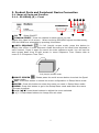
⑦ SDI OUT: Connect the HD (High Definition) Monitor with SDI input or
Connect the other devices[1920x1080, 1280x720P]
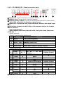
⑧ ALARM INPUT/ OUPUT
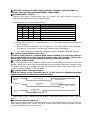
Connect the alarm input/output port to control the split display screen by
connecting a sensor or switch from outside.
- Display mode per Foreign Alarm
External input
IN1 IN2 IN3
IN4
0
0
0
0
1
0
0
0
0
1
0
0
0
0
1
0
0
0
0
1
More than 2 channels
Input
Display mode
Normal Mode
CH 1 Full Display
CH 2 Full Display
CH 3 Full Display
CH 4 Full Display
4 Splitter Display
※ Input OFF mode =“0”, Input ON mode =“1” (The GND and the Inx produce a
short circuit )
※ When an Alarm is entered, an “A” appears in the video which have received
the alarm, in the place in which the channel loss is indicated.
※ The Alarm input will not operate if an alarm signal is entered into a lost channel.
⑧-1. Alarm Input & Button Function
In Alarm input mode or external data control model, you can only enter to
the menu mode and other function button may not operate. During the
Alarm Hold Time, press any button to escape from Alarm mode.
⑧-2. Alarm Input Cancel
When the external control data or Alarm input is eliminated, it returns to the last
display mode which has been displayed before the external data has entered, after
the Alarm Hold Time is ended. You can set the Alarm Hold Time in the Alarm Time
menu in System/Display < SETUP MENU.
⑧-3. Alarm Input Timing Structure
When the Alarm or the external data is in, the screen is displayed and the
buzzer operates as following timing diagram.
External
Data IN
Screen Display
External Data IN
External Data OFF
Alarm INPUT
mode
Last
Screen
mode
Display
※ Alarm Hold Time is delayed as the Buzzer Time does(Alarm Hold Time = Buzzer
Time)
⑧-4. How to put the Alarm in
Use a contact point signal such as switches or relay to Open/Short the Inx and the
GND (Alarm Input port). Do not use any contact point with electrical signal. It may
cause any malfunction of the device.
5