1
MIPS® cJTAG Adapter User’s Manual
Document Number: MD00862
Revision 01.00
June 16, 2011
MIPS Technologies, Inc.
955 East Arques Avenue
Sunnyvale, CA 94085-4521
Copyright © 2011 MIPS Technologies Inc. All rights reserved.
1 Introduction
MIPS provides an IEEE 1149.1-compatible JTAG debug and control port called EJTAG for its processor cores.
Recently, an updated IEEE standard, 1149.7, has been published. One of the enhancements is a reduction in the number of external signals required from four to two. For some chip designs, pin count is critical, and the ability to provide debugging capabilities with only two pins could be crucial.
MIPS provides a cJTAG Adapter IP block that converts a 2-pin 1149.7 (also known as cJTAG) to the 4-pin 1149.1
debug interface present on MIPS cores. The IP resides outside the core and is treated as a separate IP block from the
point of view of design verification and implementation.
MIPS debug probes will be enhanced to support both cJTAG and legacy EJTAG. EJTAG and cJTAG use the same
14-pin connector called out in the MIPS EJTAG Specification, but when connected to cJTAG, the TDI and TDO signals are not used.
The IEEE1149.7 Specification is complex and much more flexible than is needed in this application. The IP implemented here is a subset of 1149.7.
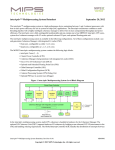
2 Overview
The cJTAG Adapter provides a probe interface consisting of two signals—TCKC and TMSC—and a device interface
consisting of four signals—SYS_TCK, SYS_TMS, SYS_TDI, and SYS_TDO. The TMSC signal is bidirectional, so
the Adapter separates the signal into three ports—TMSC_IN, TMSC_OUT, and TMSC_EN—and requires the system designer to provide the appropriate attachment to a bidirectional device pin. TCKC is sourced from the probe
(called DTS in the IEEE Specification). TMSC is bidirectional and carries control information to the Adapter and
data in both directions.
Figure 1 cJTAG High Level Pins
nTRST
nTRST
TCKC
SYS_TCK
TMSC
cJTAG Adapter
SYS_TMS
SYS_TDI
nSP
2
SYS_TDO
MIPS® cJTAG Adapter User’s Manual, Revision 01.00
Copyright © 2011 MIPS Technologies Inc. All rights reserved.
3 Protocols
3.1 Online/Offline
The Adapter can be either online or offline. When the Adapter is offline, activity on the TCKC and TMSC signals
does not affect the 1149.1 port. When online, TCKC and TMSC indirectly drive the 1149.1 port to perform JTAG
scans. There is a protocol to switch between the online and offline states.
When the Adapter is reset, it is in the offline state. A reset can be performed using the optional nTRST signal or
through a sequential protocol on TCKC/TMSC. Switching online or offline and performing reset are accomplished
using an Escape sequence described in the IEEE 1149.7 Specification. While TCKC is held high, TMSC is toggled a
certain number of times. The Adapter keeps a count of the number of edges observed on TMSC and executes the corresponding command at the next TCKC rising edge.
Figure 2 cJTAG Online
TCKC
TMSC
As described in the IEEE Specification, there may be a TMSC edge coincident with the last rising edge of TCKC
before the Escape sequence begins, and that edge may or may not be detected by the Escape logic, depending on signal skew. A single pulse that would normally be two edges could therefore be counted as three edges. Escape detection logic takes this possibility into account. The Adapter interprets TMSC edges in an Escape as described in the
following subsection.
3.2 Online Activation Code
Following the Online Escape sequence, the probe transmits an Online Activation Code (OAC), Extension Code (EC),
and Check Packet (CP), for a total of 12 TCKC pulses. The Adapter observes the control data in these codes and activates only if the requested protocol variations are supported by the Adapter. In this implementation, only one form of
activation code is supported; any other sequence of control bits will return the Adapter to the offline state.
Referring to the IEEE Standard, the OAC required is 1100, transmitted LSB first, which connotes TAP.7 star-2 scan
topology. The EC must be 1000, indicating the short form and use of the Run-Test/Idle TAP state when switching
online or offline. The CP is 0000. At the rising edge of TCKC in the last bit of the CP, the Adapter is activated. From
that point forward, activity on TCKC/TMSC is interpreted as Oscan1 format, described in the IEEE Standard, until
the Adapter is reset or otherwise taken offline.
MIPS® cJTAG Adapter User’s Manual, Revision 01.00
Copyright © 2011 MIPS Technologies Inc. All rights reserved.
3
Figure 3 cJTAG Online Activation Code
TCKC
TMSC
0
0
Escape
1
1
0
0
OAC
0
1
0
EC
0
0
0
CP
Oscan1
nSP
3.3 Oscan1
Once activated, the Adapter supports only the Oscan1 format. In Oscan1 format, the TMS, TDI, and TDO signals to
the device are multiplexed onto the TMSC signal to the probe. Three TCKC pulses are required to perform one bit of
JTAG scan. Per the IEEE Standard, the first bit of each 3-bit group (called a Scan Packet or SP) is the inverse of the
TDI signal, denoted nTDI. This is followed by TMS and finally TDO. The probe drives TMSC during the first two bit
periods, and the device drives TMSC during the last bit period.
To avoid a drive conflict in Advanced Protocol (Oscan1), TMSC is driven by its source only while TCKC is low, and
relies on a system-level keeper circuit to maintain a valid logic level while TCKC is high.
Figure 4 cJTAG Online Activation Code
TCKC
TMSC-probe
TMSC-device
nTDI
TMS
nTDI
TMS
TDO
nTDI
TDO
SYS_TCK
SYS_TDI
SYS_TMS
SYS_TDO
4
MIPS® cJTAG Adapter User’s Manual, Revision 01.00
Copyright © 2011 MIPS Technologies Inc. All rights reserved.
4 Chip Pin Requirements
The IEEE Specification requires all system designs to implement inputs with the characteristics shown in Table 1. To
support this, the Adapter provides an output signal, nSP, that indicates the Standard Protocol is active.
Table 1 cJTAG Chip Pin Requirements
External Signal Power Off Power On, nSP=0 Power on, nSP=1
TCKC
Undefined
Pull-up
Pull-up
TMSC
Undefined
Pull-up
Keeper
Care should be taken to minimize the load on TCKC and TMSC, since many components may be controlled from a
single driver. Because these are both edge-triggered signals, care must be taken in system implementations to avoid
reflections and other signal degradation that could cause incorrect operation. In large designs with more than one
load, pull-up and keeper circuitry may need to be implemented at the board-level rather than the chip-level.
5 RTL
The MIPS cJTAG Adapter IP block is located in a single RTL file at $MIPS_PROJECT/proc/design/rtl/
mips_cjtag.v, as part of the MIPS softcore package. If the cJTAG interface is not needed, the cJTAG Adapter IP
block can be totally ignored. If the cJTAG interface is needed, SoC integrators should instantiate and connect the
cJTAG Adapter IP block in the design as described in the next section.
Note that the cJTAG interface is purely a hardware conversion function and is transparent to software—there are no
configuration, control, or status registers associated with the cJTAG interface.
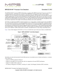
6 Integration
The cJTAG Adapter IP block is provided as a separate IP block outside the MIPS CPU Core. Figure 5 illustrates a
typical design showing how the cJTAG Adapter is integrated in an SoC. It is preferable to synthesize both the MIPS
CPU core and the cJTAG Adapter together to ease the timing constraints of the 4-wire EJTAG interface between the
MIPS CPU Core and the cJTAG Adapter.
An nTRST signal can be provided in the same way for cJTAG and EJTAG interfaces, that is, it can be provided externally as an input pin to the SoC, or it can be generated internally by the SoC in order to reset the TAP circuitry using
on-chip power-on reset logic.
MIPS® cJTAG Adapter User’s Manual, Revision 01.00
Copyright © 2011 MIPS Technologies Inc. All rights reserved.
5
Figure 5 cJTAG Integration
SoC
MIPS CPU Core
EJTAG
Tap Controller
EJTAG
4-wire
interface
TDI
TDO
TCK
TMS
cJTAG
2-wire
interface
TCKC
SYS_TDI
SYS_TDO
SYS_TCK
SYS_TMS
cJTAG
Adapter
IP Block
TCKC
TMSC_IN
TMSC_OUT
TMSC
TMSC_EN
Pull-up
or
Keeper
nSP
nTRST
nTRST
The clock of cJTAG (TCKC) interface and EJTAG (SYS_TCK) interface operate synchronously with a 3X speed ratio
as shown in Figure 6. SYS_TCK is generated based on TCKC inside the cJTAG block by masking out 2 of the pulses
every 3 cycles. It is important to constrain TCKC with a 3X frequency as the normal clock will run in the EJTAG
block.
Figure 6 TCKC and SYS_TCK
TCKC
SYS_TCK
For the rest of the cJTAG signals TMSC_*, they should be constrained in a similar way as input TDI and TMS, and
output TDO, like in the 4-wire EJTAG interface when the cJTAG Adapter is not in used.
7 Testing
The cJTAG Adapter IP block is instantiated under the MIPS softcore testbench environment in a file named
‘ejtag_tb_c_cjtag’. The testbench performs as a 2-wire debugger, sending the Escape sequence, Online Active
code, and Oscan1 to the Adapter. Figure 7 illustrate the cJTAG testbench environment.
6
MIPS® cJTAG Adapter User’s Manual, Revision 01.00
Copyright © 2011 MIPS Technologies Inc. All rights reserved.
Figure 7 cJTAG Test Environment
MIPS CPU Core
ejtab_tb_cjtag
SYS_TCK
EJTAG
Interface
cJTAG
Adapter IP
Block
SYS_TDI
SYS_TMS
TCKC
TMSC_IN
TMSC_OUT
SYS_TDO
TMSC_EN
nTRST
To see how the adapter works, TAP-related test cases such as ‘tap_fastdata-ebm32k-cjtag-zws’ can be
run under a normal softcore testbench environment. Without the ‘-cjtag-’ mode string, the test cases will run with
the normal EJTAG (IEEE1149.1) interface, bypassing the Adapter.
More testcases are also available to check the adapter:
tap_procacc1-ebm32k-cjtag-zws-prgint
tap_procacc3-ebm32k-cjtag-zws-prgint
tap_procacc4-ebm32k-cjtag-zws-prgint
tap_implreg-ebm32k-cjtag-zws-prgint
cJTAG_active-ebm32k-cjtag-zws-prgint
tap_fastdata-ebm32k-cjtag-zws-prgint
8 References
1.
MIPS® EJTAG Specification
MIPS document: MD00047
2.
IEEE Std 1149.7™-2009, IEEE Computer Society, New York NY, 2010
9 Revision History
Change bars (vertical lines) in the margins of this document indicate significant changes in the document since its last
release. Change bars are removed for changes that are more than one revision old.
Date
Revision
June 16, 2011
01.00
Description
Initial release
MIPS® cJTAG Adapter User’s Manual, Revision 01.00
Copyright © 2011 MIPS Technologies Inc. All rights reserved.
7
Unpublished rights (if any) reserved under the copyright laws of the United States of America and other countries.
This document contains information that is proprietary to MIPS Technologies, Inc. ("MIPS Technologies") one of the Imagination Technologies Group plc
companies. Any copying, reproducing, modifying or use of this information (in whole or in part) that is not expressly permitted in writing by MIPS
Technologies or an authorized third party is strictly prohibited. At a minimum, this information is protected under unfair competition and copyright laws.
Violations thereof may result in criminal penalties and fines.
Any document provided in source format (i.e., in a modifiable form such as in FrameMaker or Microsoft Word format) is subject to use and distribution
restrictions that are independent of and supplemental to any and all confidentiality restrictions. UNDER NO CIRCUMSTANCES MAY A DOCUMENT
PROVIDED IN SOURCE FORMAT BE DISTRIBUTED TO A THIRD PARTY IN SOURCE FORMAT WITHOUT THE EXPRESS WRITTEN
PERMISSION OF MIPS TECHNOLOGIES, INC.
MIPS Technologies reserves the right to change the information contained in this document to improve function, design or otherwise. MIPS Technologies does
not assume any liability arising out of the application or use of this information, or of any error or omission in such information. Any warranties, whether
express, statutory, implied or otherwise, including but not limited to the implied warranties of merchantability or fitness for a particular purpose, are excluded.
Except as expressly provided in any written license agreement from MIPS Technologies or an authorized third party, the furnishing of this document does not
give recipient any license to any intellectual property rights, including any patent rights, that cover the information in this document.
The information contained in this document shall not be exported, re-exported, transferred, or released, directly or indirectly, in violation of the law of any
country or international law, regulation, treaty, Executive Order, statute, amendments or supplements thereto. Should a conflict arise regarding the export, reexport, transfer, or release of the information contained in this document, the laws of the United States of America shall be the governing law.
The information contained in this document constitutes one or more of the following: commercial computer software, commercial computer software
documentation, or other commercial items. If the user of this information, or any related documentation of any kind, including related technical data or manuals,
is an agency, department, or other entity of the United States government ("Government"), the use, duplication, reproduction, release, modification, disclosure,
or transfer of this information, or any related documentation of any kind, is restricted in accordance with Federal Acquisition Regulation 12.212 for civilian
agencies and Defense Federal Acquisition Regulation Supplement 227.7202 for military agencies. The use of this information by the Government is further
restricted in accordance with the terms of the license agreement(s) and/or applicable contract terms and conditions covering this information from MIPS
Technologies or an authorized third party.
MIPS, MIPS I, MIPS II, MIPS III, MIPS IV, MIPS V, MIPSr3, MIPS32, MIPS64, microMIPS32, microMIPS64, MIPS-3D, MIPS16, MIPS16e, MIPS-Based,
MIPSsim, MIPSpro, MIPS-VERIFIED, Aptiv logo, microAptiv logo, interAptiv logo, microMIPS logo, MIPS Technologies logo, MIPS-VERIFIED logo,
proAptiv logo, 4K, 4Kc, 4Km, 4Kp, 4KE, 4KEc, 4KEm, 4KEp, 4KS, 4KSc, 4KSd, M4K, M14K, 5K, 5Kc, 5Kf, 24K, 24Kc, 24Kf, 24KE, 24KEc, 24KEf, 34K,
34Kc, 34Kf, 74K, 74Kc, 74Kf, 1004K, 1004Kc, 1004Kf, 1074K, 1074Kc, 1074Kf, R3000, R4000, R5000, Aptiv, ASMACRO, Atlas, "At the core of the user
experience.", BusBridge, Bus Navigator, CLAM, CorExtend, CoreFPGA, CoreLV, EC, FPGA View, FS2, FS2 FIRST SILICON SOLUTIONS logo, FS2
NAVIGATOR, HyperDebug, HyperJTAG, IASim, iFlowtrace, interAptiv, JALGO, Logic Navigator, Malta, MDMX, MED, MGB, microAptiv, microMIPS,
Navigator, OCI, PDtrace, the Pipeline, proAptiv, Pro Series, SEAD-3, SmartMIPS, SOC-it, and YAMON are trademarks or registered trademarks of MIPS
Technologies, Inc. in the United States and other countries.
All other trademarks referred to herein are the property of their respective owners.
Template: nW1.03, Built with tags: 2B
MIPS® cJTAG Adapter User’s Manual, Revision: 01.00
Copyright © 2011 MIPS Technologies Inc. All rights reserved.