1
MIPS
Verified
MIPS32® M14K™ Processor Core Datasheet
™
December 27, 2012
The MIPS32® M14K™ core from MIPS® Technologies is a member of the MIPS32 FamilyName™ processor core family. It
is a high performance, small-silicon-area, low-power, 32-bit MIPS RISC core designed for custom system-on-silicon
applications. The core is designed for semiconductor manufacturing companies, ASIC developers, and system OEMs who want
to rapidly integrate their own custom logic and peripherals with a high-performance RISC processor. The M14K core is fully
synthesizable and highly portable across processes, and can be easily integrated into full system-on-silicon designs, allowing
developers to focus their attention on end-user products. It is especially well-suited for microcontrollers and applications that
have real-time requirements with a high level of performance efficiency and security requirements.
The M14K core implements the MIPS™ Architecture Release-3 in a 5-stage pipeline. It includes support for the microMIPS™
ISA, an Instruction Set Architecture with optimized MIPS32 16-bit and 32-bit instructions that provides a significant reduction
in code size with a performance equivalent to MIPS32. The M14K core is a successor to the M4K®, designed from the same
microarchitecture, including the Microcontroller Application-Specific Extension (MCU™ ASE), enhanced interrupt handling,
lower interrupt latency, a memory protection unit (MPU), a reference design of an optimized interface for flash memory and
built-in native AMBA®-3 AHB-Lite Bus Interface Unit (BIU), and additional power saving, debug, and profiling features.
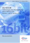
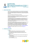
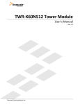
Figure 1 shows a block diagram of the M14K core. The core is divided into required and optional (shown as shaded) blocks.
Figure 1 MIPS 32® M14K™ Core Block Diagram
M14K Core
Reference Design
microMIPS
Instruction Decode
ISRAM
I/F
(MIPS32/microMIPS)
User-defined
Cop2 blk
User-defined
CorExtend blk
System
Interface
CP2
I/F
UDI
I/F
GPR
(1,2,4,8,16 sets)
Execution Unit
MDU
ALU / Shift
Atomic / LdSt
CP2 / UDI
(Perf or Area Opt)
MMU
(FMT)
ISRAM
Memory
ISRAM
I/F
SRAM
Controller
Slow Mem
I/F
MPU
DSRAM
I/F
Break Points
iFlowtrace
Fast Debug Channel
Performance Counters
Sampling
SecureDebug
Interrupt
Interface
2-wire
debug
Power
Manager
AHB-Lite
I/F
AHB-Lite
BIU
Debug/Profiling
Sys. Control
Coprocessor
Flash
I/F
DSRAM
Memory
DSRAM
I/F
cJTAG
Optional
Fixed/Required
The M14K core retains the functionality from the M4K processor core and adds some new features and functions. A summary
of key features are:
• Support for MIPS32 Architecture Release-3.
• Support for microMIPS ISA to provide better code size compression with same MIPS32 performance.
• Support for multiple shadow register sets.
• The Memory Management Unit (MMU), consisting of a simple, Fixed Mapping Translation (FMT) mechanism.
MIPS32® M14K™ Processor Core Datasheet, Revision 02.04
Copyright © 2009, 2010 MIPS Technologies Inc. All rights reserved.
MD00666
• Multiply/Divide Unit (MDU) - the MDU can be
configured for either performance or area optimizations.
The high-performance optimization supports a singlecycle 32x16-bit MAC instruction or two-cycle 32x32-bit
instructions.
• A simple SRAM-style interface that is configurable for
independent instruction and data or as a unified interface.
The SRAM interface enables deterministic response,
while maintaining high-performance operation
• Support for the MCU ASE to enhance common functions
used in microcontroller applications such as interrupts
and semaphore manipulation.
•
•
•
• microMIPS-Compatible Instruction Set
•
•
• Security features such as the Memory Protection Unit to
restrict execution capabilities from untrusted code and
SecureDebug to restrict untrusted EJTAG debug access.
• Reference design for SRAM interface to AMBA-3 AHBLite bus and flash memory.
•
• Parity support.
•
•
•
• An optional Enhanced JTAG (EJTAG version 4.52)
block allows for single-stepping of the processor as well
as instruction and data virtual address/value breakpoints.
iFlowtrace™ version 2.0 is also supported to add realtime instruction program counter and special events trace
capability for debug. Additionally, Fast Debug Channel,
Performance Counters, and PC/Data sampling functions
are added to enrich debug and profiling features on the
M14K core.
• External block to convert 4-wire EJTAG (IEEE 1149.1)
interface to 2-wire cJTAG (IEEE 1149.7) interface.
•
•
•
•
Features
• 32-bit Address and Data Paths
•
•
• MIPS32-Compatible Instruction Set
•
•
Multiply-Accumulate and Multiply-Subtract
Instructions (MADD, MADDU, MSUB, MSUBU)
Targeted Multiply Instruction (MUL)
•
•
•
Zero/One Detect Instructions (CLZ, CLO)
Wait Instruction (WAIT)
Conditional Move Instructions (MOVZ, MOVN)
• MIPS32 Enhanced Architecture Features
•
•
2
Vectored interrupts and support for external interrupt controller
Programmable exception vector base
microMIPS ISA is a build-time configurable and
run-time convertible ISA to improve code size density over MIPS32, while maintaining MIPS32 performance.
Combining both 16-bit and 32-bit opcodes, microMIPS supports all MIPS32 instructions (except
branch-likely instructions) with new optimized
encoding. Frequently used MIPS32 instructions are
available as 16-bit instructions.
Added fifteen new 32-bit instructions and thirtynine 16-bit instructions.
Stack pointer implicit in instruction.
MIPS32 assembly and ABI-compatible.
Supports MIPS architecture Modules and Userdefined Instructions (UDIs).
• MCU™ ASE
• Configurable hardware breakpoints triggered by address
match or address range.
• 5-stage pipeline
Atomic interrupt enable/disable
GPR shadow registers (one, three, seven, or fifteen
additional shadows can be optionally added to minimize latency for interrupt handlers)
Bit field manipulation instructions
Increases the number of interrupt hardware inputs
from 6 to 8 for Vectored Interrupt (VI) mode, and
from 63 to 255 for External Interrupt Controller
(EIC) mode.
Separate priority and vector generation. 16-bit vector address is provided.
Hardware assist combined with the use of Shadow
Register Sets to reduce interrupt latency during the
prologue and epilogue of an interrupt.
An interrupt return with automated interrupt epilogue handling instruction (IRET) improves interrupt latency.
Supports optional interrupt chaining.
Two memory-to-memory atomic read-modify-write
instructions (ASET and ACLR) eases commonly
used semaphore manipulation in microcontroller
applications. Interrupts are automatically disabled
during the operation to maintain coherency.
• Memory Management Unit
•
Simple Fixed Mapping Translation (FMT) mechanism
• Memory Protection Unit
•
Optional feature that improves system security by
restricting access, execution, and trace capabilities
from untrusted code in predefined memory regions.
• Simple SRAM-Style Interface
MIPS32® M14K™ Processor Core Datasheet, Revision 02.04
Copyright © 2009, 2010 MIPS Technologies Inc. All rights reserved.
•
•
•
•
•
•
Cacheless operation enables deterministic response
and reduces die-size
32-bit address and data; input byte-enables enable
simple connection to narrower devices
Single or multi-cycle latencies
Configuration option for dual or unified instruction/
data interfaces
Redirection mechanism on dual I/D interfaces permits D-side references to be handled by I-side
Transactions can be aborted
• Reference Design
•
•
•
A typical SRAM reference design is provided.
An AHB-Lite BIU reference design is provided
between the SRAM interface and AHB-Lite Bus.
An optimized interface for slow memory (Flash)
access using prefetch buffer scheme is provided.
• Parity Support
•
32 clock latency on multiply
34 clock latency on multiply-accumulate
33-35 clock latency on divide (sign-dependent)
• Multiply/Divide Unit (high-performance configuration )
•
•
•
Maximum issue rate of one 32x16 multiply per
clock via on-chip 32x16 hardware multiplier array.
Maximum issue rate of one 32x32 multiply every
other clock
Early-in iterative divide. Minimum 11 and maximum 34 clock latency (dividend (rs) sign extension-dependent)
• CorExtend® User-Defined Instruction Set Extensions
•
•
•
•
Allows user to define and add instructions to the
core at build time
Maintains full MIPS32 compatibility
Supported by industry-standard development tools
Single or multi-cycle instructions
• Multi-Core Support
•
•
•
External lock indication enables multi-processor
semaphores based on LL/SC instructions
External sync indication allows memory ordering
Debug support includes cross-core triggers
•
•
•
•
•
•
•
•
•
•
•
•
CPU control with start, stop, and single stepping
Virtual instruction and data address/value breakpoints
Hardware breakpoint supports both address match
and address range triggering
Optional simple hardware breakpoints on virtual
addresses; 8I/4D, 6I/2D, 4I/2D, 2I/1D breakpoints,
or no breakpoints
Optional complex hardware breakpoints with 8I/
4D, 6I/2D simple breakpoints
TAP controller is chainable for multi-CPU debug
Supports EJTAG (IEEE 1149.1) and compatible
with cJTAG 2-wire (IEEE 1149.7) extension protocol
Cross-CPU breakpoint support
iFlowtrace support for real-time instruction PC and
special events
PC and/or load/store address sampling for profiling
Performance Counters
Support for Fast Debug Channel (FDC)
• SecureDebug
•
An optional feature that disables access via EJTAG
in an untrusted environment
• Testability
•
Full scan design achieves test coverage in excess of
99% (dependent on library and configuration
options)
Architecture Overview
The M14K core contains both required and optional blocks,
as shown in Figure 1. Required blocks must be implemented
to remain MIPS-compliant. Optional blocks can be added to
the M14K core based on the needs of the implementation.
The required blocks are as follows:
• Instruction Decode
• Execution Unit
• General Purposed Registers (GPR)
• Coprocessor 2 interface
•
Minimum frequency: 0 MHz
Power-down mode (triggered by WAIT instruction)
Support for software-controlled clock divider
Support for extensive use of local gated clocks
• EJTAG Debug/Profiling and iFlowtrace™ Mechanism
The ISRAM and DSRAM support optional parity
detection.
• Multiply/Divide Unit (area-efficient configuration )
•
•
•
•
•
•
•
32-bit interface to an external coprocessor
• Multiply/Divide Unit (MDU)
• System Control Coprocessor (CP0)
• Power Control
MIPS32® M14K™ Processor Core Datasheet, Revision 02.04
Copyright © 2009, 2010 MIPS Technologies Inc. All rights reserved.
3
• Memory Management Unit (MMU)
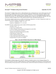
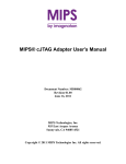
Figure 2 MIPS32® M14K™ Core Pipeline
• I/D SRAM Interfaces
• Power Management
I
E
M
Optional or configurable blocks include:
• microMIPS
I-SRAM
• Memory Protection Unit (MPU)
• Configurable instruction decoder supporting three ISA
modes: MIPS32-only, MIPS32 and microMIPS, or
microMIPS-only
• Reference Design of I/D-SRAM, BIU, Slow Memory
Interface
A
W
Bypass
Bypass
RegRd
ALU Op
I Dec D-AC
I-A1
D-SRAM
Align
RegW
Acc
RegW
Acc
RegW
Acc
RegW
I-A2
Bypass
Mul-16x16, 32x16
Bypass
Mul-32x32
Div
• Coprocessor 2 interface
• CorExtend® User-Defined Instruction (UDI) interface
• Debug/Profiling with Enhanced JTAG (EJTAG)
Controller, Break points, Sampling, Performance
counters, Fast Debug Channel, and iFlowtrace logic
I Stage: Instruction Fetch
During the Instruction fetch stage:
• An instruction is fetched from instruction SRAM.
The section "MIPS32® M14K™ Core Required Logic
Blocks" on page 5 discusses the required blocks. The section
"MIPS32® M14K™ Core Optional or Configurable Logic
Blocks" on page 11 discusses the optional blocks.
• microMIPS instructions are recoded into MIPS32
instructions if microMIPS mode is selected.
Pipeline Flow
During the Execution stage:
E Stage: Execution
• Operands are fetched from the register file.
The M14K core implements a 5-stage pipeline with a
performance similar to the M4K pipeline. The pipeline allows
the processor to achieve high frequency while minimizing
device complexity, reducing both cost and power
consumption.
The M14K core pipeline consists of five stages:
• Instruction (I Stage)
• Operands from the M and A stage are bypassed to this
stage.
• The Arithmetic Logic Unit (ALU) begins the arithmetic
or logical operation for register-to-register instructions.
• The ALU calculates the virtual data address for load and
store instructions, and the MMU performs the fixed
virtual-to-physical address translation.
• Memory (M Stage)
• The ALU determines whether the branch condition is
true and calculates the virtual branch target address for
branch instructions.
• Align (A Stage)
• Instruction logic selects an instruction address.
• Writeback (W stage)
• All multiply and divide operations begin in this stage.
The M14K core implements a bypass mechanism that allows
the result of an operation to be forwarded directly to the
instruction that needs it without having to write the result to
the register and then read it back.
M Stage: Memory Fetch
Figure 2 shows a timing diagram of the M14K core pipeline
(shown with the-high performance MDU ).
• The data SRAM access is performed for load and store
instructions.
• Execution (E Stage)
During the Memory fetch stage:
• The arithmetic ALU operation completes.
• A 16x16 or 32x16 multiply calculation completes (highperformance MDU option).
4
MIPS32® M14K™ Processor Core Datasheet, Revision 02.04
Copyright © 2009, 2010 MIPS Technologies Inc. All rights reserved.
• A 32x32 multiply operation stalls the MDU pipeline for
one clock in the M stage (high-performance MDU option
).
• A multiply operation stalls the MDU pipeline for 31
clocks in the M stage (area-efficient MDU option ).
• A multiply-accumulate operation stalls the MDU pipeline
for 33 clocks in the M stage (area-efficient MDU option
).
• A divide operation stalls the MDU pipeline for a
maximum of 34 clocks in the M stage. Early-in sign
extension detection on the dividend will skip 7, 15, or 23
stall clocks (only the divider in the fast MDU option
supports early-in detection).
• Arithmetic Logic Unit (ALU) for performing arithmetic
and bitwise logical operations. Shared adder for
arithmetic operations, load/store address calculation, and
branch target calculation.
• Address unit for calculating the next PC and next fetch
address selection muxes.
• Load Aligner.
• Shifter and Store Aligner.
• Branch condition comparator.
• Trap condition comparator.
• Bypass muxes to advance result between two adjacent
instructions with data dependency.
A Stage: Align
• Leading Zero/One detect unit for implementing the CLZ
and CLO instructions.
During the Align stage:
• Actual execution of the Atomic Instructions defined in
the MCU ASE.
• Load data is aligned to its word boundary.
• A multiply/divide operation updates the HI/LO registers
(area-efficient MDU option).
General Purpose Registers
• Multiply operation performs the carry-propagate-add.
The actual register writeback is performed in the W stage
(high-performance MDU option).
• EJTAG complex break conditions are evaluated.
The M14K core contains thirty-two 32-bit general-purpose
registers used for integer operations and address calculation.
Optionally, one, three, seven or fifteen additional register file
shadow sets (each containing thirty-two registers) can be
added to minimize context switching overhead during
interrupt/exception processing. The register file consists of
two read ports and one write port and is fully bypassed to
minimize operation latency in the pipeline.
W Stage: Writeback
Multiply/Divide Unit (MDU)
During the Writeback stage:
The M14K core includes a multiply/divide unit (MDU) that
contains a separate, dedicated pipeline for integer multiply
and divide operations. This pipeline operates in parallel with
the integer unit (IU) pipeline and does not stall when the IU
pipeline stalls. This allows the long-running MDU operations
to be partially masked by system stalls and/or other integer
unit instructions.
• A MUL operation makes the result available for
writeback. The actual register writeback is performed in
the W stage.
• For register-to-register or load instructions, the
instruction result is written back to the register file.
MIPS32® M14K™ Core Required
Logic Blocks
The required logic blocks of the M14K core (Figure 1) are
defined in the following subsections.
Execution Unit
The M14K core execution unit implements a load/store
architecture with single-cycle ALU operations (logical, shift,
add, subtract) and an autonomous multiply/divide unit.
The execution unit includes:
The MIPS architecture defines that the result of a multiply or
divide operation be placed in a pair of HI and LO registers.
Using the Move-From-HI (MFHI) and Move-From-LO
(MFLO) instructions, these values can be transferred to the
general-purpose register file.
In addition to the HI/LO targeted operations, the MIPS32
architecture also defines a multiply instruction, MUL, which
places the least significant results in the primary register file
instead of the HI/LO register pair. By avoiding the explicit
MFLO instruction, required when using the LO register, and
by supporting multiple destination registers, the throughput
of multiply-intensive operations is increased.
MIPS32® M14K™ Processor Core Datasheet, Revision 02.04
Copyright © 2009, 2010 MIPS Technologies Inc. All rights reserved.
5
Two other instructions, multiply-add (MADD) and multiplysubtract (MSUB), are used to perform the multiplyaccumulate and multiply-subtract operations, respectively.
The MADD instruction multiplies two numbers and then
adds the product to the current contents of the HI and LO
registers. Similarly, the MSUB instruction multiplies two
operands and then subtracts the product from the HI and LO
registers. The MADD and MSUB operations are commonly
used in DSP algorithms.
There are two configuration options for the MDU: 1) a higher
performance 32x16 multiplier block; 2) an area-efficient
iterative multiplier block. . The selection of the MDU style
allows the implementor to determine the appropriate
performance and area trade-off for the application.
Table 1
High-Performance Integer Multiply/Divide
Unit Latencies and Repeat Rates
Opcode
Operand Size
(mul rt)
Repeat
(div rs)
Latency Rate
16 bits
2
1
32 bits
3
2
MUL
(GPR destination)
16 bits
2
2
32 bits
3
3
DIV/DIVU
8 bits
12
11
16 bits
19
18
24 bits
26
25
32 bits
33
32
MULT/MULTU,
MADD/MADDU,
MSUB/MSUBU
(Hi/Lo destination)
MDU with 32x16 High-Performance Multiplier
The M14K core can optionally include a multiply/divide unit
(MDU) that contains a separate pipeline for multiply and
divide operations. This pipeline operates in parallel with the
integer unit (IU) pipeline and does not stall when the IU
pipeline stalls. This setup allows long-running MDU
operations, such as a divide, to be partially masked by system
stalls and/or other integer unit instructions.
The high-performance MDU consists of a 32x16 Boothrecoded multiplier, a pair of result/accumulation registers (HI
and LO), a divide state machine, and the necessary
multiplexers and control logic. The first number shown (‘32’
of 32x16) represents the rs operand. The second number (‘16’
of 32x16) represents the rt operand. The M14K core only
checks the value of the rt operand to determine how many
times the operation must pass through the multiplier. The
16x16 and 32x16 operations pass through the multiplier once.
A 32x32 operation passes through the multiplier twice.
The MDU supports execution of one 16x16 or 32x16
multiply or multiply-accumulate operation every clock cycle;
32x32 multiply operations can be issued every other clock
cycle. Appropriate interlocks are implemented to stall the
issuance of back-to-back 32x32 multiply operations. The
multiply operand size is automatically determined by logic
built into the MDU.
Table 1 lists the repeat rate (peak issue rate of cycles until the
operation can be reissued) and latency (number of cycles until
a result is available) for the multiply and divide instructions.
The approximate latency and repeat rates are listed in terms
of pipeline clocks. For a more detailed discussion of latencies
and repeat rates, refer to Chapter 2 of the MIPS32 M14K™
Processor Core Family Software User’s Manual.
MDU with Area-Efficient Option
With the area-efficient option, multiply and divide operations
are implemented with a simple 1-bit-per-clock iterative
algorithm. Any attempt to issue a subsequent MDU
instruction while a multiply/divide is still active causes an
MDU pipeline stall until the operation is completed.
Table 2 lists the latency (number of cycles until a result is
available) for the M14K core multiply and divide
instructions. The latencies are listed in terms of pipeline
clocks.
Table 2
Area-Efficient Integer Multiply/Divide Unit
Operation Latencies
Operand
Sign
Latency
MUL, MULT, MULTU
any
32
MADD, MADDU,
MSUB, MSUBU
any
34
DIVU
any
33
pos/pos
33
any/neg
34
neg/pos
35
Opcode
DIV
Regardless of the multiplier array implementation, divide
operations are implemented with a simple 1-bit-per-clock
iterative algorithm. An early-in detection checks the sign
6
MIPS32® M14K™ Processor Core Datasheet, Revision 02.04
Copyright © 2009, 2010 MIPS Technologies Inc. All rights reserved.
extension of the dividend (rs) operand. If rs is 8 bits wide, 23
iterations are skipped. For a 16-bit-wide rs, 15 iterations are
skipped, and for a 24-bit-wide rs, 7 iterations are skipped.
Any attempt to issue a subsequent MDU instruction while a
divide is still active causes an IU pipeline stall until the divide
operation has completed.
System Control Coprocessor (CP0)
In the MIPS architecture, CP0 is responsible for the virtualto-physical address translation, the exception control system,
the processor’s diagnostics capability, the operating modes
(kernel, user, and debug), and whether interrupts are enabled
or disabled. Configuration information, such as presence of
build-time options like microMIPS, CorExtend Module or
Coprocessor 2 interface, is also available by accessing the
CP0 registers.
Coprocessor 0 also contains the logic for identifying and
managing exceptions. Exceptions can be caused by a variety
of sources, including boundary cases in data, external events,
or program errors.
Interrupt Handling
The M14K core includes support for eight hardware interrupt
pins, two software interrupts, and a timer interrupt. These
interrupts can be used in any of three interrupt modes, as
defined by Release 2 of the MIPS32 Architecture:
• Interrupt compatibility mode, which acts identically to
that in an implementation of Release 1 of the
Architecture.
The reset state of the processor is interrupt compatibility
mode, such that a processor supporting Release 2 of the
Architecture, the M14K core for example, is fully compatible
with implementations of Release 1 of the Architecture.
VI or EIC interrupt modes can be combined with the optional
shadow registers to specify which shadow set should be used
on entry to a particular vector. The shadow registers further
improve interrupt latency by avoiding the need to save
context when invoking an interrupt handler.
In the M14K core, interrupt latency is reduced by:
• Speculative interrupt vector prefetching during the
pipeline flush.
• Interrupt Automated Prologue (IAP) in hardware:
Shadow Register Sets remove the need to save GPRs,
and IAP removes the need to save specific Control
Registers when handling an interrupt.
• Interrupt Automated Epilogue (IAE) in hardware:
Shadow Register Sets remove the need to restore GPRs,
and IAE removes the need to restore specific Control
Registers when returning from an interrupt.
• Allow interrupt chaining. When servicing an interrupt
and interrupt chaining is enabled, there is no need to
return from the current Interrupt Service Routine (ISR) if
there is another valid interrupt pending to be serviced.
The control of the processor can jump directly from the
current ISR to the next ISR without IAE and IAP.
GPR Shadow Registers
• Vectored Interrupt (VI) mode, which adds the ability to
prioritize and vector interrupts to a handler dedicated to
that interrupt, and to assign a GPR shadow set for use
during interrupt processing. The presence of this mode is
denoted by the VInt bit in the Config3 register. This
mode is architecturally optional; but it is always present
on the M14K core, so the VInt bit will always read as a 1
for the M14K core.
Release 2 of the MIPS32 Architecture optionally removes the
need to save and restore GPRs on entry to high-priority
interrupts or exceptions, and to provide specified processor
modes with the same capability. This is done by introducing
multiple copies of the GPRs, called shadow sets, and
allowing privileged software to associate a shadow set with
entry to kernel mode via an interrupt vector or exception. The
normal GPRs are logically considered shadow set zero.
• External Interrupt Controller (EIC) mode, which
redefines the way in which interrupts are handled to
provide full support for an external interrupt controller
handling prioritization and vectoring of interrupts. The
presence of this mode denoted by the VEIC bit in the
Config3 register. Again, this mode is architecturally
optional. On the M14K core, the VEIC bit is set externally
by the static input, SI_EICPresent, to allow system logic
to indicate the presence of an external interrupt
controller.
The number of GPR shadow sets is a build-time option. The
M14K core allows 1 (the normal GPRs), 2, 4, 8, or 16 shadow
sets. The highest number actually implemented is indicated
by the SRSCtlHSS field. If this field is zero, only the normal
GPRs are implemented.
Shadow sets are new copies of the GPRs that can be
substituted for the normal GPRs on entry to kernel mode via
an interrupt or exception. Once a shadow set is bound to a
kernel-mode entry condition, references to GPRs operate
exactly as one would expect, but they are redirected to
registers that are dedicated to that condition. Privileged
software may need to reference all GPRs in the register file,
MIPS32® M14K™ Processor Core Datasheet, Revision 02.04
Copyright © 2009, 2010 MIPS Technologies Inc. All rights reserved.
7
even specific shadow registers that are not visible in the
current mode, and the RDPGPR and WRPGPR instructions
are used for this purpose. The CSS field of the SRSCtl register
provides the number of the current shadow register set, and
the PSS field of the SRSCtl register provides the number of the
previous shadow register set that was current before the last
exception or interrupt occurred.
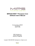
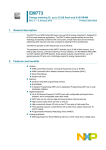
Figure 3 M14K™ Core Virtual Address Map
0xFFFFFFFF
Fixed Mapped
0xFF400000
0xFF3FFFFF
0xFF200000
0xF1FFFFFF
Memory/EJTAG1
kseg3
Fixed Mapped
0xE0000000
If the processor is operating in VI interrupt mode, binding of
a vectored interrupt to a shadow set is done by writing to the
SRSMap register. If the processor is operating in EIC interrupt
mode, the binding of the interrupt to a specific shadow set is
provided by the external interrupt controller and is configured
in an implementation-dependent way. Binding of an
exception or non-vectored interrupt to a shadow set is done
by writing to the ESS field of the SRSCtl register. When an
exception or interrupt occurs, the value of SRSCtlCSS is copied
to SRSCtlPSS, and SRSCtlCSS is set to the value taken from the
appropriate source. On an ERET, the value of SRSCtlPSS is
copied back into SRSCtlCSS to restore the shadow set of the
mode to which control returns.
0xDFFFFFFF
0xC0000000
0xBFFFFFFF
0xA0000000
0x9FFFFFFF
Kernel Virtual Address Space
kseg2
Fixed Mapped, 512 MB
Kernel Virtual Address Space
Unmapped, 512 MB
Uncached
Kernel Virtual Address Space
kseg0
Unmapped, 512 MB
0x80000000
0x7FFFFFFF
User Virtual Address Space
Mapped, 2048 MB
Modes of Operation
The M14K core implements three modes of operation:
• User mode is most often used for applications programs.
• Kernel mode is typically used for handling exceptions and operating-system kernel functions, including CP0 management and I/O device accesses.
• Debug mode is used during system bring-up and
software development. Refer to the EJTAG section
for more information on debug mode.
Figure 3 shows the virtual address map of the MIPS
Architecture.
kseg1
kuseg
0x00000000
1. This space is mapped to memory in user or kernel mode,
and by the EJTAG module in debug mode.
Memory Management Unit (MMU)
The M14K core contains a simple Fixed Mapping Translation
(FMT) MMU that interfaces between the execution unit and
the SRAM controller.
Fixed Mapping Translation (FMT)
A FMT is smaller and simpler than the full Translation
Lookaside Buffer (TLB) style MMU found in other MIPS
cores. Like a TLB, the FMT performs virtual-to-physical
address translation and provides attributes for the different
segments. Those segments that are unmapped in a TLB
implementation (kseg0 and kseg1) are translated identically
by the FMT.
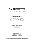
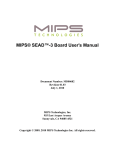
Figure 4 shows how the FMT is implemented in the M14K
core.
8
MIPS32® M14K™ Processor Core Datasheet, Revision 02.04
Copyright © 2009, 2010 MIPS Technologies Inc. All rights reserved.
Figure 4 Address Translation During SRAM Access
with FMT Implementation
Physical
Address
Virtual
Instruction Address
Address
Calculator
Inst
SRAM
SRAM
interface
FMT
Data
Address
Calculator
Data
SRAM
Physical
Address
Virtual
Address
SRAM Interface Controller
Instead of caches, the M14K core contains an interface to
SRAM-style memories that can be tightly coupled to the core.
This permits deterministic response time with less area than
is typically required for caches. The SRAM interface includes
separate uni-directional 32-bit buses for address, read data,
and write data.
Dual or Unified Interfaces
The SRAM interface includes a build-time option to select
either dual or unified instruction and data interfaces.
The dual interface enables independent connection to
instruction and data devices. It generally yields the highest
performance, because the pipeline can generate simultaneous
I and D requests, which are then serviced in parallel.
For simpler or cost-sensitive systems, it is also possible to
combine the I and D interfaces into a common interface that
services both types of requests. If I and D requests occur
simultaneously, priority is given to the D side.
Back-stalling
Typically, read and write transactions will complete in a
single cycle. However, if multi-cycle latency is desired, the
interface can be stalled to allow connection to slower devices.
Redirection
When the dual I/D interface is present, a mechanism exists to
divert D-side references to the I-side, if desired. The
mechanism can be explicitly invoked for any other D-side
references, as well. When the DS_Redir signal is asserted, a
D-side request is diverted to the I-side interface in the
following cycle, and the D-side will be stalled until the
transaction is completed.
Transaction Abort
The core may request a transaction (fetch/load/store/sync) to
be aborted. This is particularly useful in case of interrupts.
Because the core does not know whether transactions are restartable, it cannot arbitrarily interrupt a request which has
been initiated on the SRAM interface. However, cycles spent
waiting for a multi-cycle transaction to complete can directly
impact interrupt latency. In order to minimize this effect, the
interface supports an abort mechanism. The core requests an
abort whenever an interrupt is detected and a transaction is
pending (abort of an instruction fetch may also be requested
in other cases). The external system logic can choose to
acknowledge or to ignore the abort request.
Connecting to Narrower Devices
The instruction and data read buses are always 32 bits in
width. To facilitate connection to narrower memories, the
SRAM interface protocol includes input byte-enables that can
be used by system logic to signal validity as partial read data
becomes available. The input byte-enables conditionally
register the incoming read data bytes within the core, and thus
eliminate the need for external registers to gather the entire 32
bits of data. External muxes are required to redirect the
narrower data to the appropriate byte lanes.
Lock Mechanism
The SRAM interface includes a protocol to identify a locked
sequence, and is used in conjunction with the LL/SC atomic
read-modify-write semaphore instructions.
Sync Mechanism
The interface includes a protocol that externalizes the
execution of the SYNC instruction. External logic might
choose to use this information to enforce memory ordering
between various elements in the system.
External Call Indication
The instruction fetch interface contains signals that indicate
that the core is fetching the target of a subroutine call-type
instruction such as JAL or BAL. At some point after a call,
there will typically be a return to the original code sequence.
If a system prefetches instructions, it can make use of this
information to save instructions that were prefetched and are
likely to be executed after the return.
Hardware Reset
The M14K core has two types of reset input signals: SI_Reset
and SI_ColdReset. Functionally, these two signals are ORed
MIPS32® M14K™ Processor Core Datasheet, Revision 02.04
Copyright © 2009, 2010 MIPS Technologies Inc. All rights reserved.
9
together within the core and then used to initialize critical
hardware state.
Both reset signals can be asserted either synchronously or
asynchronously to the core clock, SI_ClkIn, and will trigger a
Reset exception. The reset signals are active high and must be
asserted for a minimum of 5 SI_ClkIn cycles. The falling edge
triggers the Reset exception.
The primary difference between the two reset signals is that
SI_Reset sets a bit in the Status register; this bit could be used
by software to distinguish between the two reset signals, if
desired. The reset behavior is summarized in Table 3.
Table 3 Reset Types
SI_Reset
SI_ColdReset
0
0
Normal operation, no reset.
1
0
Reset exception; sets
StatusSR bit.
X
1
Action
Reset exception.
One (or both) of the reset signals must be asserted at poweron or whenever hardware initialization of the core is desired.
A power-on reset typically occurs when the machine is first
turned on. A hard reset usually occurs when the machine is
already on and the system is rebooted.
In debug mode, EJTAG can request that a soft reset (via the
SI_Reset pin) be masked. It is system-dependent whether this
functionality is supported. In normal mode, the SI_Reset pin
cannot be masked. The SI_ColdReset pin is never masked.
Power Management
The M14K core offers a number of power management
features, including low-power design, active power
management, and power-down modes of operation. The core
is a static design that supports slowing or halting the clocks,
which reduces system power consumption during idle
periods.
The M14K core provides two mechanisms for system-level
low-power support:
• Register-controlled power management
• Instruction-controlled power management
Register-Controlled Power Management
The state of the RP bit is available externally via the SI_RP
signal. The external agent then decides whether to place the
device in a low-power mode, such as reducing the system
clock frequency.
Three additional bits,StatusEXL, StatusERL, and DebugDM
support the power management function by allowing the user
to change the power state if an exception or error occurs while
the M14K core is in a low-power state. Depending on what
type of exception is taken, one of these three bits will be
asserted and reflected on the SI_EXL, SI_ERL, or
EJ_DebugM outputs. The external agent can look at these
signals and determine whether to leave the low-power state to
service the exception.
The following four power-down signals are part of the system
interface and change state as the corresponding bits in the
CP0 registers are set or cleared:
• The SI_RP signal represents the state of the RP bit (27) in
the CP0 Status register.
• The SI_EXL signal represents the state of the EXL bit (1)
in the CP0 Status register.
• The SI_ERL signal represents the state of the ERL bit (2)
in the CP0 Status register.
• The EJ_DebugM signal represents the state of the DM bit
(30) in the CP0 Debug register.
Instruction-Controlled Power Management
The second mechanism for invoking power-down mode is by
executing the WAIT instruction. When the WAIT instruction
is executed, the internal clock is suspended; however, the
internal timer and some of the input pins (SI_Int[5:0], SI_NMI,
SI_Reset, and SI_ColdReset) continue to run. Once the CPU
is in instruction-controlled power management mode, any
interrupt, NMI, or reset condition causes the CPU to exit this
mode and resume normal operation.
The M14K core asserts the SI_Sleep signal, which is part of
the system interface bus, whenever the WAIT instruction is
executed. The assertion of SI_Sleep indicates that the clock
has stopped and the M14K core is waiting for an interrupt.
Local clock gating
The majority of the power consumed by the M14K core is in
the clock tree and clocking registers. The core has support for
extensive use of local gated-clocks. Power-conscious
implementors can use these gated clocks to significantly
reduce power consumption within the core.
The RP bit in the CP0 Status register provides a software
mechanism for placing the system into a low-power state.
10
MIPS32® M14K™ Processor Core Datasheet, Revision 02.04
Copyright © 2009, 2010 MIPS Technologies Inc. All rights reserved.
MIPS32® M14K™ Core Optional or
Configurable Logic Blocks
The M14K core contains several optional or configurable
logic blocks, shown as shaded in the block diagram in Figure
1.
Reference Design
The M14K core contains a reference design that shows a
typical usage of the core with:
• Dual I-SRAM and D-SRAM interface with fast
memories (i.e., SRAM) for instruction and data storage.
• Optimized interface for slow memory (i.e., Flash
memory) access by having a prefetch buffer and a wider
Data Read bus (i.e., IS_RData[127:0]) to speed up IFetch performance.
• AHB-lite bus interface to the system bus if the memory
accesses are outside the memory map for the SRAM and
Flash regions. AHB-Lite is a subset of the AHB bus
protocol that supports a single bus master. The interface
shares the same 32-bit Read and Write address bus and
has two unidirectional 32-bit buses for Read and Write
data.
16-bit or 32-bit instructions will be fetched and recoded to
legacy MIPS32 instruction opcodes in the pipeline’s I stage,
so that the M14K core can have the same M4K
microarchitecture. Because the microMIPS instruction
stream can be intermixed with 16-bit halfword or 32-bit word
size instructions on halfword or word boundaries, additional
logic is in place to address the word misalignment issues, thus
minimizing performance loss.
Memory Protection Unit
The Memory Protection Unit can be configured to have from
1 to 16 memory protection regions. Each region is enabled by
a set of Watch registers that define the address, size and
protection of each memory region. The Memory Protection
Unit control and Watch registers are implemented by CDMM
(Common Device Memory Map) registers. After they have
been programmed, these control registers can be locked to
prohibit later modifications. Once programmed, a Protection
Exception will be triggered when an Instruction Fetch or Data
Access matches the address of the protected memory region
or any modification of the EBase (base address of exception
vectors) register was attempted. Each protected region can
also disable the iFlowtrace capability. Typically, the Memory
Protection Unit improves system security by disabling access
to bootcode and preventing execution of non-trusted kernel
mode code.
The reference design is optional and can be modified by the
user to better fit the SOC design requirement.
Figure 5 Reference Design Block Diagram.
Prefetch Buffer 128-bit
IS I/F
Internal
Flash
32-bit
M14K
AHB Lite
Bridge
AHB-Lite Bus
DS I/F
32-bit
Internal
ISRAM &
DSRAM
External
Memory I/F
microMIPS™ ISA
The M14K core supports the microMIPS ISA, which
contains all MIPS32 ISA instructions (except for branchlikely instructions) in a new 32-bit encoding scheme, with
some of the commonly used instructions also available in 16bit encoded format. This ISA improves code density through
the additional 16-bit instructions while maintaining a
performance similar to MIPS32 mode. In microMIPS mode,
Coprocessor 2 Interface
The M14K core can be configured to have an interface for an
on-chip coprocessor. This coprocessor can be tightly coupled
to the processor core, allowing high-performance solutions
integrating a graphics accelerator or DSP, for example.
The coprocessor interface is extensible and standardized on
MIPS cores, allowing for design reuse. The M14K core
supports a subset of the full coprocessor interface standard:
32b data transfer, no Coprocessor 1 support, single issue inorder data transfer to coprocessor, one out-of-order data
transfer from coprocessor.
The coprocessor interface is designed to ease integration with
customer IP. The interface allows high-performance
communication between the core and coprocessor. There are
no late or critical signals on the interface.
CorExtend® User-defined Instruction
Extensions
An optional CorExtend User-defined Instruction (UDI) block
enables the implementation of a small number of applicationspecific instructions that are tightly coupled to the core’s
MIPS32® M14K™ Processor Core Datasheet, Revision 02.04
Copyright © 2009, 2010 MIPS Technologies Inc. All rights reserved.
11
execution unit. The interface to the UDI block is external to
the M14K core.
Such instructions may operate on a general-purpose register,
immediate data specified by the instruction word, or local
state stored within the UDI block. The destination may be a
general-purpose register or local UDI state. The operation
may complete in one cycle or multiple cycles, if desired.
Debug Support
The M14K core provides for an optional Enhanced JTAG
(EJTAG) interface for use in the software debug of
application and kernel code. In addition to standard user
mode and kernel modes of operation, the M14K core provides
a Debug mode that is entered after a debug exception (derived
from a hardware breakpoint, single-step exception, etc.) is
taken and continues until a debug exception return (DERET)
instruction is executed. During this time, the processor
executes the debug exception handler routine.
The EJTAG interface operates through the Test Access Port
(TAP), a serial communication port used for transferring test
data in and out of the M14K core. In addition to the standard
JTAG instructions, special instructions defined in the EJTAG
specification specify which registers are selected and how
they are used.
Debug Registers
Four debug registers (DEBUG, DEBUG2, DEPC, and DESAVE)
have been added to the MIPS Coprocessor 0 (CP0) register
set. The DEBUG and DEBUG2 registers show the cause of the
debug exception and are used for setting up single-step
operations. The DEPC (Debug Exception Program Counter)
register holds the address on which the debug exception was
taken, which is used to resume program execution after the
debug operation finishes. Finally, the DESAVE (Debug
Exception Save) register enables the saving of generalpurpose registers used during execution of the debug
exception handler.
To exit debug mode, a Debug Exception Return (DERET)
instruction is executed. When this instruction is executed, the
system exits debug mode, allowing normal execution of
application and system code to resume.
EJTAG Hardware Breakpoints
There are several types of simple hardware breakpoints
defined in the EJTAG specification. These stop the normal
operation of the CPU and force the system into debug mode.
There are two types of simple hardware breakpoints
implemented in the M14K core: Instruction breakpoints and
12
Data breakpoints. Additionally, complex hardware
breakpoints can be included, which allow detection of more
intricate sequences of events.
The M14K core can be configured with the following
breakpoint options:
• No data or instruction, or complex breakpoints
• One data and two instruction breakpoints, without
complex breakpoints
• Two data and four instruction breakpoints, without
complex breakpoints
• Two data and six instruction breakpoints, with or without
complex breakpoints
• Four data and eight instruction breakpoints, with or
without complex breakpoints
Instruction breakpoints occur on instruction execution
operations, and the breakpoint is set on the virtual address. A
mask can be applied to the virtual address to set breakpoints
on a binary range of instructions.
Data breakpoints occur on load/store transactions, and the
breakpoint is set on a virtual address value, with the same
single address or binary address range as the Instruction
breakpoint. Data breakpoints can be set on a load, a store, or
both. Data breakpoints can also be set to match on the
operand value of the load/store operation, with bytegranularity masking. Finally, masks can be applied to both
the virtual address and the load/store value.
In addition, the M14K core has a configurable feature to
support data and instruction address-range triggered
breakpoints, where a breakpoint can occur when a virtual
address is either within or outside a pair of 32-bit addresses.
Unlike the traditional address-mask control, address-range
triggering is not restricted to a power-of-two binary
boundary.
Complex breakpoints utilize the simple instruction and data
breakpoints and break when combinations of events are seen.
Complex break features include:
• Pass Counters - Each time a matching condition is seen, a
counter is decremented. The break or trigger will only be
enabled when the counter has counted down to 0.
• Tuples - A tuple is the pairing of an instruction and a
data breakpoint. The tuple will match if both the virtual
address of the load or store instruction matches the
instruction breakpoint, and the data breakpoint of the
resulting load or store address and optional data value
matches.
MIPS32® M14K™ Processor Core Datasheet, Revision 02.04
Copyright © 2009, 2010 MIPS Technologies Inc. All rights reserved.
• Priming - This allows a breakpoint to be enabled only
after other break conditions have been met. Also called
sequential or armed triggering.
• Qualified - This feature uses a data breakpoint to qualify
when an instruction breakpoint can be taken. Once a load
matches the data address and the data value, the
instruction break will be enabled. If a load matches the
address, but has mis-matching data, the instruction break
will be disabled.
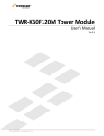
Figure 6 FDC Overview
M14K
Receive from 32
Probe to Core
Transmit from 32
Core to Probe
Performance Counters
Performance counters are used to accumulate occurrences of
internal predefined events/cycles/conditions for program
analysis, debug, or profiling. A few examples of event types
are clock cycles, instructions executed, specific instruction
types executed, loads, stores, exceptions, and cycles while the
CPU is stalled. There are two, 32-bit counters. Each can count
one of the 64 internal predefined events selected by a
corresponding control register. A counter overflow can be
programmed to generate an interrupt, where the interrupt
handler software can maintain larger total counts.
Probe
EJTAG
TAP
FDC
FIFO
TDI
FIFO
TDO
Tap Controller
TMS
iFlowtrace™
The M14K core has an option for a simple trace mechanism
called iFlowtrace. This mechanism only traces the instruction
PC, not data addresses or values. This simplification allows
the trace block to be smaller and the trace compression to be
more efficient. iFlowtrace memory can be configured as offchip, on-chip, or both.
PC/Address Sampling
iFlowtrace also offers special-event trace modes when
normal tracing is disabled, namely:
This sampling function is used for program profiling and hotspots analysis. Instruction PC and/or Load/Store addresses
can be sampled periodically. The result is scanned out
through the EJTAG port. The Debug Control Register (DCR)
is used to specify the sample period and the sample trigger.
• Function Call/Return and Exception Tracing mode to
trace the PC value of function calls and returns and/or
exceptions and returns.
Fast Debug Channel (FDC)
The M14K core includes optional FDC as a mechanism for
high bandwidth data transfer between a debug host/probe and
a target. FDC provides a FIFO buffering scheme to transfer
data serially, with low CPU overhead and minimized waiting
time. The data transfer occurs in the background, and the
target CPU can either choose to check the status of the
transfer periodically, or it can choose to be interrupted at the
end of the transfer.
• Breakpoint Match mode traces the breakpoint ID of a
matching breakpoint and, for data breakpoints, the PC
value of the instruction that caused it.
• Filtered Data Tracing mode traces the ID of a matching
data breakpoint, the load or store data value, access type
and memory access size, and the low-order address bits
of the memory access, which is useful when the data
breakpoint is set up to match a binary range of addresses.
• User Trace Messages. The user can instrument their code
to add their own 32-bit value messages into the trace by
writing to the Cop0 UTM register.
• Delta Cycle mode works in combination with the above
trace modes to provide a timestamp between stored
events. It reports the number of cycles that have elapsed
since the last message was generated and put into the
trace.
cJTAG Support
The M14K core provides an external conversion block which
converts the existing EJTAG (IEEE 1149.1) 4-wire interface
at the M14K core to a cJTAG (IEEE 1149.7) 2-wire interface.
cJTAG reduces the number of wires from 4 to 2 and enables
MIPS32® M14K™ Processor Core Datasheet, Revision 02.04
Copyright © 2009, 2010 MIPS Technologies Inc. All rights reserved.
13
the support of Star-2 scan topology in the system debug
environment.
Full mux-based scan for maximum test coverage is
supported, with a configurable number of scan chains. ATPG
test coverage can exceed 99%, depending on standard cell
libraries and configuration options.
Figure 7 cJTAG Support
M14K
EJTAG
4-wire
interface
EJTAG
TDI
TDO
TCK
TMS
Tap
Controller
cJTAG
2-wire
interface
cJTAG
Conversion
Block
Internal Scan
TMSC
TCK
Memory BIST
Memory BIST for the on-chip trace memory is optional.
Memory BIST can be inserted with a CAD tool or other userspecified method. Wrapper modules and special side-band
signal buses of configurable width are provided within the
core to facilitate this approach.
Build-Time Configuration Options
SecureDebug
SecureDebug improves security by disabling untrusted
EJTAG debug access. An input signal is used to disable
debug features, such as Probe Trap, Debug Interrupt
Exception (EjtagBrk and DINT), EJTAGBOOT instruction,
and PC Sampling.
Testability
Testability for production testing of the core is supported
through the use of internal scan and memory BIST.
Table 4
The M14K core allows a number of features to be customized
based on the intended application. Table 4 summarizes the
key configuration options that can be selected when the core
is synthesized and implemented.
For a core that has already been built, software can determine
the value of many of these options by checking an appropriate
register field. Refer to the MIPS32® M14K™ Processor Core
Family Software User’s Manual for a more complete
description of these fields. The value of some options that do
not have a functional effect on the core are not visible to
software.
Build-time Configuration Options
Option
Choices
Software Visibility
Integer register file sets
1, 2, 4, 8 or 16
SRSCtlHSS
Integer register file implementation style
Flops or generator
N/A
ISA support
MIPS32 only, or
microMIPS only, or
MIPS32 and microMIPS present
Config3ISA
Multiply/divide implementation style
High performance or min area
ConfigMDU
Memory Protection Unit
Present or not. If present 1 - 16 regions
N/A
Adder implementation style
Structured or Simple
N/A
EJTAG TAP controller
Present or not
N/A
EJTAG TAP Fast Debug Channel (FDC)
Present or not (even when TAP is present)
DCRFDCI
EJTAG TAP FDC FIFO size
Two TX/two RX, or eight TX/four RX 32-bit registers
FDCFG
* These bits indicate the presence of an external block. Bits will not be set if interface is present, but block is not.
14
MIPS32® M14K™ Processor Core Datasheet, Revision 02.04
Copyright © 2009, 2010 MIPS Technologies Inc. All rights reserved.
Table 4
Build-time Configuration Options (Continued)
Option
Choices
Software Visibility
Instruction/data hardware breakpoints
0/0, 2/1, 4/2, 6/2, or 8/4
DCRInstBrk, IBSBCN
DCRDataBrk, DBSBCN
Hardware breakpoint trigger by
Address match, or
Address match and address range
IBCnhwart, DBCnhwart
Complex breakpoints
0/0, 6/2, or 8/4
DCRCBT
Performance Counters
Present or not
Config1PC
iFlowtrace hardware
Present or not
Config3ITL
iFlowtrace memory location
On-core or off-chip
IFCTLofc
iFlowtrace on-chip memory size
256B - 8MB
N/A
CorExtend interface
Present or not
ConfigUDI*
Coprocessor2 interface
Present or not
Config1C2*
SRAM interface style
Separate instruction/data or unified
ConfigDS
SRAM Parity
Present or not
ErrCtlPE
Interrupt synchronizers
Present or not
N/A
Interrupt Vector Offset
Compute from Vector Input or Immediate Offset
N/A
Clock gating
Top-level, integer register file array, fine-grain, or none
N/A
PC Sampling
Present or not
Debug Control Register
Data Address Sampling
Present or not
Debug Control Register
PRID
User defined Processor Identification
PRIDCompanyOpt
* These bits indicate the presence of an external block. Bits will not be set if interface is present, but block is not.
1bm
Revision History
Revision
Date
Description
01.00
November 2, 2009
• Initial 1_0_0 release.
02.00
December 17, 2010
• 2_0_0 Maintenance release.
02.01
September 30, 2011
02.02
March 12, 2012
• 2_1a_0 Patch release.
02.03
April 30, 2012
• 2_2_0 Maintenance release.
02.04
December 27, 2012
• 2_x_x Maintenance release.
• 2_1_0 Maintenance release.
MIPS32® M14K™ Processor Core Datasheet, Revision 02.04
Copyright © 2009, 2010 MIPS Technologies Inc. All rights reserved.
15
16
MIPS32® M14K™ Processor Core Datasheet, Revision 02.04
Copyright © 2009, 2010 MIPS Technologies Inc. All rights reserved.
Copyright © 2009, 2010 MIPS Technologies, Inc. All rights reserved.
Unpublished rights (if any) reserved under the copyright laws of the United States of America and other countries.
This document contains information that is proprietary to MIPS Technologies, Inc. ("MIPS Technologies"). Any copying, reproducing, modifying or use of this
information (in whole or in part) that is not expressly permitted in writing by MIPS Technologies or an authorized third party is strictly prohibited. At a
minimum, this information is protected under unfair competition and copyright laws. Violations thereof may result in criminal penalties and fines.
Any document provided in source format (i.e., in a modifiable form such as in FrameMaker or Microsoft Word format) is subject to use and distribution
restrictions that are independent of and supplemental to any and all confidentiality restrictions. UNDER NO CIRCUMSTANCES MAY A DOCUMENT
PROVIDED IN SOURCE FORMAT BE DISTRIBUTED TO A THIRD PARTY IN SOURCE FORMAT WITHOUT THE EXPRESS WRITTEN
PERMISSION OF MIPS TECHNOLOGIES, INC.
MIPS Technologies reserves the right to change the information contained in this document to improve function, design or otherwise. MIPS Technologies does
not assume any liability arising out of the application or use of this information, or of any error or omission in such information. Any warranties, whether
express, statutory, implied or otherwise, including but not limited to the implied warranties of merchantability or fitness for a particular purpose, are excluded.
Except as expressly provided in any written license agreement from MIPS Technologies or an authorized third party, the furnishing of this document does not
give recipient any license to any intellectual property rights, including any patent rights, that cover the information in this document.
The information contained in this document shall not be exported, reexported, transferred, or released, directly or indirectly, in violation of the law of any
country or international law, regulation, treaty, Executive Order, statute, amendments or supplements thereto. Should a conflict arise regarding the export,
reexport, transfer, or release of the information contained in this document, the laws of the United States of America shall be the governing law.
The information contained in this document constitutes one or more of the following: commercial computer software, commercial computer software
documentation or other commercial items. If the user of this information, or any related documentation of any kind, including related technical data or manuals,
is an agency, department, or other entity of the United States government ("Government"), the use, duplication, reproduction, release, modification, disclosure,
or transfer of this information, or any related documentation of any kind, is restricted in accordance with Federal Acquisition Regulation 12.212 for civilian
agencies and Defense Federal Acquisition Regulation Supplement 227.7202 for military agencies. The use of this information by the Government is further
restricted in accordance with the terms of the license agreement(s) and/or applicable contract terms and conditions covering this information from MIPS
Technologies or an authorized third party.
MIPS, MIPS I, MIPS II, MIPS III, MIPS IV, MIPS V, MIPSr3, MIPS32, MIPS64, microMIPS32, microMIPS64, MIPS-3D, MIPS16, MIPS16e, MIPS-Based,
MIPSsim, MIPSpro, MIPS Technologies logo, MIPS-VERIFIED, MIPS-VERIFIED logo, 4K, 4Kc, 4Km, 4Kp, 4KE, 4KEc, 4KEm, 4KEp, 4KS, 4KSc, 4KSd,
M4K, M14K, 5K, 5Kc, 5Kf, 24K, 24Kc, 24Kf, 24KE, 24KEc, 24KEf, 34K, 34Kc, 34Kf, 74K, 74Kc, 74Kf, 1004K, 1004Kc, 1004Kf, 1074K, 1074Kc, 1074Kf,
R3000, R4000, R5000, ASMACRO, Atlas, "At the core of the user experience.", BusBridge, Bus Navigator, CLAM, CorExtend, CoreFPGA, CoreLV, EC,
FPGA View, FS2, FS2 FIRST SILICON SOLUTIONS logo, FS2 NAVIGATOR, HyperDebug, HyperJTAG, IASim, JALGO, Logic Navigator, Malta, MDMX,
MED, MGB, microMIPS, OCI, PDtrace, the Pipeline, Pro Series, SEAD, SEAD-2, SmartMIPS, SOC-it, System Navigator, and YAMON are trademarks or
registered trademarks of MIPS Technologies, Inc. in the United States and other countries.
All other trademarks referred to herein are the property of their respective owners.
Template: nDb1.03, Built with tags: 2B
MIPS32® M14K™ Processor Core Datasheet, Revision 02.04
Copyright © 2009, 2010 MIPS Technologies Inc. All rights reserved.
MD00666