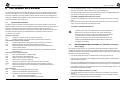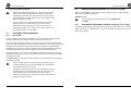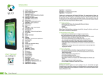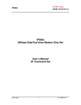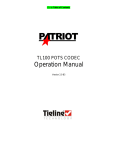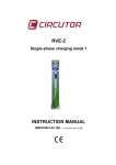
1
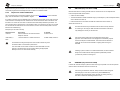
Adesys bv, Wateringen Notes SEVERA® English 8.6 Severa is a registered trademark of Adesys bv, Wateringen, NL www.adesys.nl Published 28-06-2007 44 Severa Adesys bv, Wateringen Adesys bv, Wateringen Contents GENERAL 1 1.1 INTRODUCTION..............................................................................................................................5 PSTN / GSM model .........................................................................................................................5 1.1.2 GPRS model ....................................................................................................................................5 1.1.3 Severa series features .....................................................................................................................5 1.1.4 Pictograms used ..............................................................................................................................6 1.2 CHECKING YOUR ORDER ............................................................................................................6 1.2.1 The environment ..............................................................................................................................7 1.3 GUARANTEE AND LIABILITY .......................................................................................................7 IDENTIFICATION 2.1 3 2 Connect the earth leakage of the Compri-HX to the earthing block using the shortest possible connection (as per the Priva prescriptions). • Connect the GND of the Severa’s power supply to the earthing block using again the shortest possible connection, preferably with mounting wire of at least 1mm2 an a maximum length of 1m. • Connect the power cable for the Severa to the 24VAC power supply using a 1AT fuse. The diameter of this power cable must be at least 0.5mm2, and it length no more than 5m. 8 CONNECTION DIAGRAM...............................................................................................................8 INSTALLATION 10 3.1 LOCATION ....................................................................................................................................10 3.2 DIGITAL INPUTS...........................................................................................................................10 3.3 OUTPUTS ......................................................................................................................................10 3.4 RS-232 (COM) PORTS..................................................................................................................10 3.5 SIM-KAART (Only with Severa GSM).........................................................................................11 3.6 ANTENNE (only with Severa GSM) ............................................................................................11 3.7 POWER SUPPLY ..........................................................................................................................12 3.7.1 Mains adapter SV-20 .....................................................................................................................12 3.7.2 Built-in emergency power supply...................................................................................................12 3.7.3 Severa PSTN .................................................................................................................................12 3.7.4 Severa GSM...................................................................................................................................12 3.8 PROG / RESET BUTTON .............................................................................................................13 4 Compri-HX / Severa mounting recommendations • 5 1.1.1 2 5 8.5.2 SETTING UP THE SEVERA 14 4.1 INSTALLING AND USING SEVPROG .........................................................................................14 4.2 DEFINITIONS OF THE TERMS USED .........................................................................................14 4.2.1 Main message (Location name) ....................................................................................................14 4.2.2 Status message .............................................................................................................................15 4.2.3 Dial-back time ................................................................................................................................15 4.2.4 Contact input point .........................................................................................................................15 4.2.5 Delay ..............................................................................................................................................15 4.2.6 Correction report (Idle)...................................................................................................................15 4.2.7 Report block on input channels during mains failures...................................................................15 4.2.8 Telephone number and dialling sequence.....................................................................................16 4.2.9 Required basic settings..................................................................................................................16 HOW THE SEVERA WORKS 17 Severa Severa 43 Adesys bv, Wateringen Adesys bv, Wateringen 5.1 FUNCTIONS.................................................................................................................................. 17 5.2 REPORT PROCEDURE ............................................................................................................... 17 5.3 STRUCTURE OF THE REPORT MESSAGE............................................................................... 18 5.4 REPORTING STATUS CHANGES .............................................................................................. 18 5.5 REPORTING MAINS MALFUNCTIONS (only with built-in emergency power supply) ......... 19 5.6 CONFIRMING A REPORT MESSAGE ........................................................................................ 20 In the Priva package, an initialization string should be entered, which the Compri then shoots into the Severa. In no event may this string include &F. 5.6.1 Severa GSM .................................................................................................................................. 20 5.6.2 Severa PSTN................................................................................................................................. 21 An example of a properly working string is ATM0E0V0S0=2S7=80 5.7 ANALOGUE INPUTS.................................................................................................................... 21 The last part (S7=80) is only necessary if it takes longer to establish modem connections than the standard timeout of 50 seconds. This is the case if, for example, the Severa sends its reports to an ARA system where all incoming options are active for “Programming COM port”, i.e. all acceptance reports, semadigit and modem messages. 5.7.1 Setting up Alarms .......................................................................................................................... 21 5.7.2 Severa menu ................................................................................................................................. 23 5.8 REMOTE SWITCHING (only with the Severa GSM) ................................................................. 24 5.9 REQUESTING VERSION NUMBER (only with the Severa GSM) ............................................ 25 8.5 SEVERA–COMPRI LINK 8.5.1 Modem settings To use the Severa in combination with a Compri system, a number of factors should be taken into consideration. 5.10 The following modem settings must be programmed: 6 • Baudrate • Parity (8N1) Consult the specifications of the equipment used for the exact settings. A special communication cable is available for both the Compri-8 and the Compri-HX. The article number for this is SV-22 (RS-232 cable Severa // Compri – RJ-10 / RJ-45 / adapter Sub-D9). When using the RJ-10 connector the handshake pin has to be set on DCD (set via “Modem” tab in SevProg). The firmware of the ARA / Smart-Alarm line interface must be at least X14P or X25P. As with all ARA systems, speech must be spoken into the line interface! 42 Severa RECHARGING THE INTERNAL BATTERY (emergency power supply) ................................. 25 THE SEVERA AS A MODEM 26 6.1 The basic AT commands ............................................................................................................ 26 6.1.1 ATA................................................................................................................................................ 27 6.1.2 ATD................................................................................................................................................ 28 6.1.3 ATE................................................................................................................................................ 28 6.1.4 ATH................................................................................................................................................ 28 6.1.5 ATI ................................................................................................................................................. 28 6.1.6 ATL (only with Severa PSTN) ....................................................................................................... 28 6.1.7 ATM (only with Severa PSTN) ...................................................................................................... 28 6.1.8 ATO ............................................................................................................................................... 29 6.1.9 ATQ ............................................................................................................................................... 29 6.1.10 ATS................................................................................................................................................ 29 6.1.11 ATV................................................................................................................................................ 29 6.1.12 ATX................................................................................................................................................ 30 6.1.13 ATZ ................................................................................................................................................ 30 6.1.14 AT\N (only with Severa PSTN)...................................................................................................... 30 6.1.15 AT%C (only with Severa PSTN).................................................................................................... 30 6.1.16 AT&D ............................................................................................................................................. 31 6.1.17 AT&F.............................................................................................................................................. 31 6.1.18 AT&W ............................................................................................................................................ 31 6.1.19 AT+CMGS ..................................................................................................................................... 31 6.1.20 AT+CSQ ........................................................................................................................................ 32 6.1.21 +++................................................................................................................................................. 32 6.1.22 Basic AT command settings for Severa PSTN and GSM modems.............................................. 32 6.2 EXPERT MODEM USERS............................................................................................................ 33 6.2.1 The inside of the Severa ............................................................................................................... 33 6.2.2 Starting a modem connection........................................................................................................ 33 Severa 3 Adesys bv, Wateringen 6.2.3 7 Adesys bv, Wateringen Expert user modem initialisation....................................................................................................34 TECHNICAL SPECIFICATIONS 35 8.4 Reporting to ARA In order to send reports to ARA-pro (Adesys Alarm Registration and Processing system) alarm centre, the message must contain the following text (format). 8 ANNEX 37 8.1 LED STATUSINDICATIE ..............................................................................................................37 8.2 LIST OF SETTINGS (only with Severa GSM).............................................................................39 8.3 BATTERY-POWERED SEVERA MODEL ....................................................................................40 8.4 Reporting to ARA .........................................................................................................................41 8.5 SEVERA–COMPRI LINK ..............................................................................................................42 8.5.1 Modem settings..............................................................................................................................42 8.5.2 Compri-HX / Severa mounting recommendations .........................................................................43 8.6 Notes .............................................................................................................................................44 <location> = location code e.g. <0001> (enter in line 1, “main message”) <alarm><SV> = alarm number (contact input point) e.g.<1><SV> Since there are no separate entry options for alarm and idle reports, the number of the alarm input point must be followed by <SV>. The line interface will then see from the IDLE or ACTIVE indication whether the report is an alarm or an idle report. Forwarding to ARA-pro is only possible if the system is equipped with an SMS receiver, type AR-MT2SG 4 Severa Severa 41 Adesys bv, Wateringen 8.3 Adesys bv, Wateringen 1 GENERAL BATTERY-POWERED SEVERA MODEL The functionality of the battery-powered Severa (type identified as “BW”) differs from that of the mains-powered models in several respects, namely: 1.1 INTRODUCTION This manual relates to Severa modems with firmware version 5 or higher. 1.1.1 • The supply voltage originates from 2 IEC LR6 (Alkaline, format AA) batteries (included). The amount of electricity used in the sleep mode is only a few µA. • The Severa does NOT work with pulse contacts! As such, contact input points must remain active at least until the moment that the SMS message is sent. • When an alarm input point has been activated, the Severa comes out of its sleep mode. It then logs onto the network of a telecom provider (as per the SIM card fitted), using its built-in GSM engine, after which the SMS message is sent. Since the Severa is not constantly logged onto the telecom provider’s network (to save energy), this procedure takes some time to process (+/- 90 sec). • No dial-back acceptance time can be programmed. After the SMS message has been sent, the Severa immediately returns to its sleep mode. • If the Severa has been in sleep mode for more than 30 days, it automatically restarts for 0.5 second to test the batteries. However, it does not test the condition of the batteries, it only measures whether they are still above the “empty” level. If they are below that level, the Severa automatically sends a “battery empty” message. This report is the same as the “mains failure” report of the mains-powered models. • • The push button on the print can be used to check the performance of the indicator LEDs. If that button is pressed, all LEDs will light up, and a “battery empty” test is performed. If the button is pressed for more than 3 seconds, the Severa will be start up and will remain on for 1 minute. This allows the user to read any statuses and the antenna level. With this model, the software version CANNOT be called up as described in chapter 5.8. PSTN / GSM model The Severa is an alarm system raising the alarm and forwarding notification of malfunctions and calamities by telephone for both manned and automated installations and processes. Depending on the model used, forwarding is done via either the fixed (PSTN) or mobile network (GSM). Changes in status are forwarded as SMS message. Depending on the type ordered the Severa comes complete with all contact inputs, relay outputs, inputs for analogue signals and/or modem functionality. The user can set the SMS text for reporting changes, which is also the case with the desired dialling sequence and reset procedure. 1.1.2 GPRS model The Severa is also available as a special model for GPRS applications with its own manual available. With this Severa you are "always on line" with your applications in the field. Severa’s unique "auto log on" concept replaces the often complex GPRS technology with standard modem technology. Consult our website for more information or contact one of our employees. 1.1.3 Severa series features • Adjustable delays • Built-in emergency power supply (may vary per model) • Mains monitoring (may vary per model) • Serial interface RS232 connection (9 pole sub D and RJ10 connector) • Settings and SMS texts are permanently stored in the Severa’s internal flash memory. • The Severa can be programmed using the ‘SevProg’ program, which can be downloaded free of charge at www.adesys.nl. This programming tool software is also available on CD-ROM and can be ordered from Adesys as an optional extra. To make the best possible use of all the features offered by the Severa, we recommend that you read this user manual carefully. 40 Severa Severa 5 Adesys bv, Wateringen 1.1.4 Adesys bv, Wateringen Pictograms used 8.2 LIST OF SETTINGS (only with Severa GSM) This user manual uses various pictograms. COMMAND ACTIVITY CONFIRMATION Request software version number VERSION: SV-x.xx #OA1# Output point 1 becomes active Severa confirms: Output command. #OA2# Output point 2 becomes active Severa confirms: Output command. #OA12# Output points 1 and 2 become active Severa confirms: Output command. #OI1# Output point 1 becomes idle Severa confirms: Output command. #OI2# Output point 2 becomes idle Severa confirms: Output command. #OI12# Output points1 and 2 become idle Severa confirms: Output command. #OP1# Output 1 will be active for 2 seconds No confirmation The standard order includes: #OP2# Output 2 will be active for 2 seconds No confirmation • Severa #OP12# No confirmation • Connection clamps Outputs 1 and 2 will be active for 2 seconds • Modem/programming cable set • Telephone wire with country-specific telecom plug (only with Severa PSTN) • This user manual • Guarantee card The meanings of these pictograms are as follows: #V# Tip or matter of attention Action to be performed ➀ Reference in an illustration 1.2 CHECKING YOUR ORDER Check the packaging for any damage. If your order is damaged or incomplete upon receipt, contact your supplier immediately. Optional extras are: • Antenna and antenna cable (various models, such as a vandalism-resistant model) • Mains adapter 230VC / 12VDC (article number SV-20) • RS-232, 9-polig Sub-D cable male / female (article no. TB-14) • USB-SERIAL adapter (article no. TB-18) • ‘SevProg’ programming tool software (article no. SV-40) 6 Severa Severa 39 Adesys bv, Wateringen Adesys bv, Wateringen 1.2.1 On/busy (green) The environment GSM PSTN Off Severa is switched off Same On Severa is switched on and is ready to send messages Same Flashing rapidly Severa is starting up or is sending an SMS message Busy with modem module Same Flash 1x Input channel 1 is active Same Flash 2x Input channel 2 is active Same Each Severa is subjected to extensive testing by ADESYS prior to shipment. Flash 3x Input channel 3 is active Same Flash 4x Input channel 4 is active Same ADESYS offers one year’s guarantee, provided that the guarantee card accompanying the Severa is completed and returned to us. Flash 5x Input channel 5 is active Same Flash 6x Input channel 6 is active Same Flash 7x Input channel 7 is active Same The following will terminate the guarantee: Flash 8x Input channel 8 is active Same • If the malfunction was caused by gross negligence or inexpert installation • TX / Rx (green) -- PSTN If the product has been opened and/or any repairs or changes have been made without the permission of ADESYS Off -- No incoming or outgoing data • If the serial number proves to have been removed or damaged. Flashing This product contains materials that might harm the environment. To protect the environment, if the product is to be replaced at the end of its useful life, please do not deposit it with your household waste. You can return the product to your supplier or turn it in at a special depot. 1.3 GUARANTEE AND LIABILITY Data received or sent (along with RS-232 signal) ADESYS cannot be held liable for any consequential damages if the alarm stagnates. Alarms do not offer a 100% guarantee against damages, but are merely tools for preventing damages. Consequently, we recommend that you discuss the remaining risk with your insurance company. If multiple input channels are active, each channel’s status is indicated consecutively. If all LEDs start flashing simultaneously when the Severa is started up, it is possible that it is not connected to the mains and the optional internal emergency battery is too low. 38 Severa Severa 7 Adesys bv, Wateringen Adesys bv, Wateringen 2 IDENTIFICATION 8 ANNEX 2.1 8.1 CONNECTION DIAGRAM LED STATUSINDICATIE Network (yellow) 8 Severa GSM PSTN Off No antenna level Not connected to telephone line On Modem connection (online) Same Flash 1x Antenna level 1%-20% Connected to telephone line Flash 2x Antenna level 21%-40% -- Flash 3x Antenna level 41%-60% (lowest recommended level) -- Flash 4x Antenna level 61%-80% -- Flash 5x Antenna level 81%-100% -- Flash 1x long (as dial tone) Dialling in Dialling in Rapid flashing Establishing modem connection Same Error (red) GSM PSTN Off No errors Same Flash 1x General error Same Flash 2x No SIM card inserted Input point active but no telephone line connected Flash 3x Incorrect PIN code -- Flash 4x 3x incorrect PIN code, enter PUK code -- Flash 5x Mains failure Same Flash 6x Incorrect or no telephone or service centre number entered Same Flash 7x No telephone number entered in the first position of the sequence of numbers of input channel Same Severa 37 Adesys bv, Wateringen Weight: Max. temperature for use: Electronics: NiMH battery (emergency power supply): 36 Adesys bv, Wateringen 130gr. excluding battery 155gr. including battery -20°C to +55°C -5°C to +55°C Severa 1 SIM card holder (only with GSM models) 2 LED status indicator: antenna level (network), error messages (error) and general status (on/busy) 3 Serial interface RS-232, RJ-10 connector (com) 4 Programming / resetting key (prog/reset) 5 Input / output connection clamps 6 Mains connection clamps 7 Power switch (on/off) 8 Antenna connection type SMA female (only with GSM models) 9 RJ-11 telephone connection (only with PSTN models) 10 Serial interface RS-232, 9-pole sub-D connector 11 DIN rail mounting clamp Severa 9 Adesys bv, Wateringen Adesys bv, Wateringen 3 INSTALLATION 7 TECHNICAL SPECIFICATIONS 3.1 Digital input terminals: 0, 2, 8 points activated by potential-free NO or NC contact or open collector output points. Minimum open clamp voltage is 1.8V, maximum is 3.6V. Maximum contact current is 350µ @ 3.6V. Analogue input terminals: 2 or 4 voltage inputs (0…10V) 2 or 4 current inputs (0…20mA) (for some versions only) Output relay terminals: 0 or 2 points (only with Severa GSM) relay contact, output points NO and NC maximum charge allowed 100V- 1A AC/DC 8 externally activated channels mains failure channel LOCATION Place the Severa outside the effects of direct sunlight or other heat sources. Select the place where you will mount the Severa in such a way that no moisture can enter the machine. The Severa can be mounted without using screws on a TS35 rail. The surrounding temperatures permitted range from -20°C to +55°C for the electro nic equipment and from -5ºC to +55ºC for the NiMH battery (emergency power supply). The Severa has greater transmitting power than standard mobile telephones. In certain cases, this may affect the functioning of nearby electronic equipment. The effects depend on the distance between the antenna and the surrounding equipment. 3.2 Report channels: DIGITAL INPUTS Report in the event of: The digital contact inputs can be used with either make-contacts or breaker contacts. Activate the entries only using potential-free contacts or open-collector outputs. The open clamp voltage should be no less than 1.8V and no more than 3.6V. The contact voltage should be no more than 350µA @ 3.6V. active mode idle mode, with externally activated channels Number of dialling numbers: 8 numbers per input point, up to 20 digits per number Report using: SMS message Confirmation of message: by dial-back (based on caller identification with Severa GSM) by returning the SMS message, based on caller identification (only with Severa GSM) Mobile network: Antenna connection: GSM 900/1800 MHz (dual band) connector type SMA female Fixed telephone network: Telephone connection: PSTN Connector type RJ45 COM port: Serial interface RS-232, sub-D 9 pol. or RJ-10. Pin configuration RJ10: TXD-out pin 1, RXD-in pin 2, HANDSHAKE pin 3, GND pin 4 Power supply: If the Severa is used as an external modem it is necessary to choose between the 4 pole RJ-10 or 9 pole SUB-D connections. Default the 9 pole SUB-D connector is selected. This can be changed via the SevProg using the tab “Modem” and “Handshake” settings. Severa GSM: 8-35VDC (min. 3W) or 15-28VAC (min. 5VA) Not galvanic separated Severa PSTN: 8-35VDC (min. 2W) or 8-28VAC (min. 3VA) Galvanic separated Battery-powered model: 2x IEC LR6 (alkaline, size AA) Built-in emergency power supply: NiMH battery 2.4V - 700mAh, standby time is 15 hours (depending on the condition of the battery). “Flowcont” or “no flowcont” (=standard) applies to the 9 pole SUB-D connection. When using the 4 pole RJ-10 connection a choice has to be made from DCD, DTR or RI. Measurements of DIN rail (TS35) housing: 23mm x 95mm x 104mm (w x h x d) 3.3 OUTPUTS The outputs can only be switched remotely. The maximum voltage allowed for these relay contacts is 100V / 1A AC/DC. The internal insulation distances are not suitable for direct switching using 230V. Always use an additional relay with a spool voltage of no more than 100V. 3.4 RS-232 (COM) PORTS The Severa is set up by means of the available RS-232 (com) ports. The cable set included and the downloadable software programming tool SevProg, are used for this purpose. Which RS-232 (com) port is used makes no difference to setting up. This depends on which control signals are used for the application that is employed. However, a lot of applications do not use these signals. 10 Severa IP-65 wall housing: (excluding swivels) Severa 122mm x 120mm x 39mm (w x h x d) 35 Adesys bv, Wateringen Adesys bv, Wateringen programmed using the AT interpreter are sent to the module. With expert user initialization, the AT commands programmed in the telephone book are sent to the modem module. 3.5 6.2.3 Insert the required SIM card as follows: Expert user modem initialisation The AT command set for the modem modules can be found at www.adesys.nl, on the download page. This documentation is only available in English. If a modem connection is to be initialized using a command from the expert AT set, that command must be stored in the telephone book. Fields 100 to 109 are reserved for these commands. Omit the letters “AT” before the command. The Severa will send all fields preceded by the letters “AT” and concluding with a carriage return to the modem module. If a command is too long for one field, the next field can be used for the rest of the command, in which case the final symbol in the first field must be a backslash (\). SIM-CARD (Only with Severa GSM) Read the instructions for setting the PIN code etc. that are shown on the separate form. • Switch the Severa off ➆. • The SIM cardholder is made accessible using a pointed object to press the adjacent button, which releases the holder ➀. • Place the SIM card in the holder and slide the holder back into the Severa ➀. Switch the Severa on ➆. The SIM card should only be inserted when the Severa is fully switched off. Inserting or removing the SIM card while the Severa is switched on may damage the memory of the SIM card. Examples (AT set used for PSTN): Telephone book Description To module +GCI=42 Set the modem for use with the German telephone network Limit the modem to a V22bis connection AT+GCI=42<cr> +MS=V22B,1,\ 2400 We strongly advise against using a prepaid SIM card for alarm purposes. The mobile network is not equipped to automatically request the level of telephone credit available. This means that the absence of credit will not be noticed and will lead to outgoing alerts coming to a standstill! AT+MS=V22B,1,2400<cr> Commands that change the response of the modem module may have an adverse effect on the Severa’s performance. The commands for the modem modules for PSTN and GSM do not all respond in the same ways. We recommend reading the appropriate description of the AT command set carefully. If dialling up with a modem on a GSM model Severa, the Severa should always have a SIM card with data supplement (GSM data)! Consult your telecom provider concerning this. 3.6 ANTENNE (only with Severa GSM) In areas with reduced reception, place the antenna as high as possible. Connect the optional antenna cable to the Severa’s antenna connection ➇. After having connected the antenna, always check the antenna signal’s field strength (no more than 5 pulses of the yellow network LED). Changes in the signal strength will be reported very slowly (±30 sec.); bear this in mind when relocating the antenna etc. 34 Severa Severa 11 Adesys bv, Wateringen 3.7 POWER SUPPLY 3.7.1 Mains adapter SV-20 Adesys bv, Wateringen 6.2 A 230VAC / 12VDC mains adapter power supply (article number SV-20) is available for the Severa as an option. Take care to check the polarity of the connection block when connecting it to the supply cable. The yellow connecting wire on the supply cable is positive (+) and the white connecting wire is negative (-). in Built-in emergency power supply Severa GSM Connect the Severa GSM to a direct-voltage power supply of 8 to 35VDC (minimum of 3W) or a 15 to 28 VAC transformer (minimum of 5VA). The Severa GSM power plug is not galvanically separated from the other connections. The power connection’s GND plug is linked directly to the input connector and COM port’s GND plug inside. Connecting the Severa GSM to an application (process regulator, PLC, computer, active answering machine, etc.) without galvanic separation if the Severa GSM is connected to the same power supply creates a real risk of earth loops and/or short circuits in that power supply! arbitrator Severa modem module telecom network PSTN or GSM internal AT command interpreter com The Severa contains an intern AT command interpreter that allows the basic AT set to function. If a modem connection has to be established, this will be done through the modem module, which depends on the type of telecom network the Severa uses. Differences between modem modules are taken care of by the interpreter, making the Severa’s interchangeable. To prevent the modem and alarm functions in the Severa from interfering with one another, an arbitrator has been inserted, which ensures defined switching from the alarm function to modem communication and vice versa. 6.2.2 As such, we recommend that in the case of any doubt you always check whether or not the application to which the Severa GSM is to be connected has galvanic separation. You can verify this simply using an ohm meter to measure the resistance between the power source and each connector of the application to which the Severa is to be hooked up. If that resistance is less than 12 alarm reporter Severa PSTN Connect the Severa PSTN to a direct-voltage power supply of 8 to 35VDC (minimum of 2W) or an 8 to 28 VAC transformer (minimum of 3VA). The Severa PSTN’s power plug is galvanically separated from the other connections, allowing the Severa PSTN to be simply connected to existing power supplies. Always insert a 1AT fuse between the power supply or transformer and the Severa. 3.7.4 out Severa Severa modems are also available with a built-in emergency power supply as an option. This consists of a charger and two NiMH rechargeable batteries. The life expectancy of these batteries depends very much on the circumstances under which they are used. Regularly check that the emergency power supply is working correctly by disconnecting the mains supply. It is important that the batteries are replaced if they are defective otherwise they could damage the Severa. 3.7.3 The inside of the Severa Using the expert commands requires a degree of understanding of how the Severa is constructed inside. When the Severa is not supplied by the mains adapter mentioned above, the connection instructions given in articles 3.7.3 and 3.7.4 apply. 3.7.2 As mentioned above, the Severa’s basic set of AT commands will generally be sufficient for modem communications. However, in some cases one of the many other AT may be necessary for establishing a connection. The Severa offers options in this respect. Using these options, however, requires a thorough understanding of modems. Incorrect use may result in unpredictable responses from the Severa. Moreover, it is important to bear in mind that these expert commands have to be used differently with the various Severa models. 6.2.1 An extra fuse is not necessary here. EXPERT MODEM USERS Starting a modem connection With the ATD and ATA commands, or by auto answer, a modem connection is started. The internal AT command interpreter will ask use of the modem module via the arbitrator. If this works, i.e. if no alarm occurs, that module is fully initialized. Next, the connection process is started. There are 3 stages in the initialization of the modem module: the basic init, the AT interpreter init, and the expert user init. The basic initialization deals with the modem module’s responses, allowing the interpreter to control those responses consistently. Next, the settings that the user has Severa 33 Adesys bv, Wateringen Adesys bv, Wateringen It is not a problem if these commands are already in your application software. The Severa can be set up in such a way that unknown AT commands can be ignored. A simple OK will be sent. This setting relates to SevProg. 10M, they are not fully separated and there is a risk of malfunctions and/or damage to the Severa and/or the application. The SMS Service Centre Address is taken from the SIM card. If the Severa can be connected to an existing power supply, always insert a 1AT fuse in the supply clamps’ + or AC connectors. This command is also supported for analogue (PSTN) lines. In this case it is then necessary to set the switchboard number using SevProg. The Severa can also be powered using the optional 230VAC network adapter (article no. SV-20), in which case no fuse is required between the power supply and the Severa. The maximum number of characters that can be sent is 145 for GSM and 45 for PSTN. 3.8 6.1.20 Requesting the RF reception quality. The value is given in a linear scale from 0 to 31 where 0 equals no reception (0%) and 31 equals maximum reception strength (100%). 6.1.21 PROG / RESET BUTTON AT+CSQ +++ When the Severa is switched on, you can check the functioning of the indicator LEDs using the prog/reset button. When you press this button, all LEDs will light up. The prog/reset button also allows you to confirm all active input points at once. For more information, see chapter 5.6 CONFIRMING A REPORT MESSAGE This prog/reset button also serves for activating the Severa’s programming mode. See chapter Fout! Verwijzingsbron niet gevonden. If the modem is set to data mode, the +++ command can be used to return to the command mode. In command mode, for example, the connection can be terminated (see ATH). In order to prevent premature switching, the +++ symbols must be preceded and followed by 1 second’s data silence. In other words, the modem switches to command mode after 1sec. idle, +++, 1sec. idle. The modem response is OK. After that response, commands can be entered. 6.1.22 Basic AT command settings for Severa PSTN and GSM modems The following basic AT command settings can be stored in the Severa’s memory by using SevProg. Go to the “Modem” tab to do this. PSTN modem AT&W (basic init): E1V1Q0X4&D0 AT&W (basic init): %C1\N3L2M0 AT&W (basic init): S0=0S7=90 GSM / GPRS modem AT&W (basic init): E1V1Q0X4&D0 AT&W (basic init): niets invullen AT&W (basic init): S0=0S7=90 The “auto answer” function is off with this setting. The command S0=0 should be changed to S0=2 in order to have the modem respond after two rings for example. This “auto answer” function can still be set remotely on a Severa that is already in operation by sending an SMS message with the following text: #AA# The modem will now respond after one ring. However, this remotely entered setting will not be stored in the flash memory permanently! 32 Severa Severa 13 Adesys bv, Wateringen Adesys bv, Wateringen 4 SETTING UP THE SEVERA AT%C3 6.1.16 4.1 Data compression only activated for incoming data AT&D INSTALLING AND USING SEVPROG This software programming tool for the PC is used to set up all Severa models. The program can be downloaded free from Adesys’ website (www.adesys.nl). All basic and modem settings are stored in the Severa’s internal flash memory. It is not possible to store the settings on the SIM card! SevProg has to be installed on your PC before it can be used. Follow the directions given on your PC screen during the installation process precisely. As soon as the installation process has been completed start the program by using the shortcut or the MS Windows program menu. Modem connections can be terminated by sending the DTR signal. However, if this signal is missing, the functionality should be switched off using the AT&D command. AT&D0 AT&D1 AT&D2 6.1.17 DTR signal is ignored and is assumed to be “ON” . This allows you to work with terminals that do not feature DTR signals Not applicable “hang-up” If the DTR signal is idle, the modem switches “OFF-LINE” AT&F AT&F returns all modem settings to the factory settings. The response is OK. Connect the Severa to a power supply and make a connection between the Severa and the PC using the serial cable set, which is included. 6.1.18 It makes no difference which of the RS-232 ports is used for setting up. The (serial) cable set, which is included, is suitable for both connection possibilities. It is also unimportant which of the included adapters you use. Both the DCD (Data Carrier Detect) and the RI (Ring Indicator) adapter are suitable for this purpose. AT&W stores all current settings, and so determines the new start-up position when the modem is started and after the ATZ command is entered. As with every Severa setting, this setting is stored in the telephone book. It can also be used to directly program the modem when programming the Severa. This setting can also be adjusted manually, although great care should be observed. Wrong settings may have unpredictable consequences. If your PC has no serial connection it is possible to use a USB port on the computer by using the USB SERIAL adapter, which is available as an option. This adapter can be ordered from Adesys stating article number TB-18. The Severa can now be switched on. After switching on the Severa set it to programming mode by pressing the prog/reset button. After doing this all the LEDs will start to flash. This is only possible while the green LED flashes on/busy. If this doesn’t happen switch the Severa off and repeat the previous procedure. Now select the COM port that the Severa is connected to using the “Options” tab. At the bottom of the SevProg window, the “Status info” will show whether the Severa has been connected properly. Enter all the required set-up data in the necessary fields and if necessary follow any instructions displayed in the right-hand text field. Once all the necessary data has been entered the settings will be stored in the Severa’s internal flash memory by pressing the “Program” button. 6.1.19 AT&W AT+CMGS By using the AT+CMGS command it is possible for most GSM modems to send an SMS message immediately. This command is also available for the Severa from firmware version 3.25. Command: +CMGS=<telno><CR> <telno> = Telephone number of the recipient of the SMS message in +316….. format <CR> = Carriage return After the CR the modem will react with the > character. You can now enter your text. Enter CTRLZ to close your text. The modem will react to this with +CMGS: 000 and an OK to indicate that it has been sent successfully. If you want to interrupt the command after the > character, then you can send an ESC instead of a CTRL-Z. This completes the Severa set-up. Example: 4.2 DEFINITIONS OF THE TERMS USED AT+CMGS=”+31622446098”[CR] 4.2.1 Main message (Location name) > Test message[CTR-Z] The main message is always displayed first with all report messages. If the messages in question are sent to a central point from various locations, the main message can be used to report the location from where the status is reported. The maximum number of characters for the message is twelve. 14 Severa +CMGS: 000[CR] OK Setting up different SMS settings, such as the SMS Service Centre Address (+CSCA) and the Message Format (+CMGF) is not supported. Severa 31 Adesys bv, Wateringen 6.1.12 Adesys bv, Wateringen 4.2.2 ATX This command is used to set two functions. Firstly, it determines whether the modem uses the signals from the telephone switchboard, such as the dialling tone and busy tone. . In addition, it determines the level of detail of the responses (see the response table below for further information). After this command, the modem responds with OK. ATX0 ATX1 ATX2 ATX3 ATX4 6.1.13 Telephone signals are not used, basic responses Telephone signals are not used, detailed responses Only the dialling tone is used, detailed responses Only the busy tone is used, detailed responses All telephone signals are used, detailed responses The status message is linked to an input channel. In this way, for example, the machine can be indicated that is causing the status change on the input channel in question. The maximum number of characters for this part of the message is twelve. The maximum number of characters that can be displayed in the main and status messages is twelve. If more than twelve characters are entered, only the first twelve will be displayed in the SMS message. 4.2.3 ATZ In addition to using the AT&W command, the original position can also be adjusted directly in the telephone book via the programming environment. If this has not been set properly, the response to the ATZ command will be ERROR. AT\N (only with Severa PSTN) The Severa modem has built-in protocols to check the connection for errors, and to compress the data. There are two different protocols available for this: V.42 and MNP. Naturally, these protocols can only be used if the modems at both ends of the connection are fitted with them. Please note that some modems do not feature these protocols. Despite the possibility to detect their presence automatically, it is sometimes necessary to switch of the protocols entirely. The AT\N command regulates the activation and deactivation (see also AT%C). The modem responds to the AT\N command with OK. AT\N0 AT\N1 AT\N2 AT\N3 6.1.15 All protocols are deactivated. Recommended for communication with modems that do not feature error checks and compression Idem Automatic detection of MNP error check protocol Automatic detection of V.41 error check protocol (also possible with MNP active) Please note that status changes of other input points will not be reported until a current report has been completed. Consequently, the dial-back time should be selected carefully. 4.2.4 4.2.5 If the input channel returns to the idle mode within the delay, no report procedure will be started. 4.2.6 Correction report (Idle) If you wish, once the input channel has returned to the idle mode, a correction report can be sent. In order to activate this report, set this report field to “yes”. If no dial-back time has been set, a correction report will be sent to all numbers set for the input point in question. If a dial-back time has been set, only the telephone number to which the final report message is sent will receive a correction report. 4.2.7 30 Delay The delay can be used to set a delay for the status message (active and idle). This means that the report will not be started until the contact has been activated or deactivated for longer than this amount of time. The maximum value that can be set is “3600” seconds. AT%C (only with Severa PSTN) Data compression deactivated Data compression fully activated Data compression only activated for outgoing data Contact input point Both make-contacts and breaker contacts can be used. Set to “NO” (standard setting) if a makecontact is used and “NC” for a breaker contact. NO stands for Normally Open (make-contact) and NC for Normally Closed (breaker contact). If an error check protocol has been activated using the AT\N command, AT%C can be used to determine whether the transmitted data is to be compressed. Depending on the type of data, this can save considerable amounts of time. AT%C0 AT%C1 AT%C2 Dial-back time The dial-back time determines the space of time within which a report message is to be confirmed. Confirmation can be either by sending back an SMS message or by phoning the Severa. The maximum value that can be set is “60” minutes. If it is set to “0”, alarms need not be confirmed. ATZ resets the modem to its original position. All settings return to the last recorded value (see also AT&W), and if the modem is connected that connection is terminated. The modem response is OK. 6.1.14 Status message Report block on input channels during mains failures It may be desirable to block status reports during mains failures until the failures have been resolved. To activate the block, enter “yes”. In the event of In the event of a mains failure, any current reports will immediately be terminated. The input points for which the status report has not Severa Severa 15 Adesys bv, Wateringen Adesys bv, Wateringen yet started or for which the status report has been terminated will not be restarted until the mains failure has been resolved. ATM3 4.2.8 6.1.8 Telephone number and dialling sequence The maximum number of digits that can be entered per field is 20. The maximum number of telephone numbers per input channel is eight. There can be different telephone numbers and dialling sequences per input. The sequence for dialling out is always from 1 to 8. ATQ ATQ switches the modem’s responses on and off. Some automated systems cannot process these modem responses. In such cases, the responses should be switched off. The response to the ATQ command is OK. For example: 0651627384 should be entered as +31651627384 4.2.9 ATO ATO can be used to switch from the command mode (see +++) to the modem mode. This can only be done if a modem connection has already been made. The modem responds with CONNECT (..). 6.1.9 The telephone numbers must always be entered in the international format, with the country code. For Dutch numbers this is +31. Speaker is on when the connection is being made, and is off during dialling and the connection Required basic settings ATQ0 ATQ1 Before you can start programming, you must first complete a number of required basic settings/actions: (Quit off) modem sends responses (Quit on) modem does not send responses For the SIM-card 6.1.10 Place the SIM card that you wish to use in a mobile telephone or SIM card reader/writer to enter the following settings. ATS Change the SIM card’s “old” PIN code to the new PIN code to be used with the Severa, or else deactivate the PIN code. Activate caller identification (using your provider’s service menu). The modem has what are known as S registers for storing certain settings. Using the ATS command, these registers can be read and information can be entered. Use a question mark (?) to read an S register. For example, the command ATS0? reads S register 0. The modem responds with the value of the register requested, followed by OK. Writing information to these registers uses the equal sign (=), for example ATS7=55 sets the value of S register 7 to 55. Deactivate Voicemail (using your provider’s service menu). The Severa has the following S registers: Program your provider’s SMS switchboard number (only necessary near borders). ATS0 regulates the automatic answering of calls to the modem. If S0 is set to 0, the modem does not answer automatically. Every value greater than 0 signifies the number of rings after which the modem is to answer. The modem is started automatically, in the same way is with the ATA command. The modem then sends the response CONNECT (…) or BUSY. If any data is transmitted via the COM port before that time, the connection is terminated (without any response from the modem). For the receiving telephone Activate caller identification (only necessary for accepting/confirming alarms). Deactivating caller identification and activating Voicemail may cause the Severa to malfunction. If caller identification is deactivated, it will be impossible to confirm reports. ATS7 determines the maximum amount of time to be spent making a modem connection. If the connection has not been established after the set time (in seconds), the attempts are stopped and the modem returns to the idle status. 6.1.11 ATV Numerical codes are necessary for some automated systems that control the modem. The modem responds with OK (or 0). ATV0 ATV1 16 Severa Severa Modem sends numerical responses (numerical codes) Modem sends text responses 29 Adesys bv, Wateringen 5 HOW THE SEVERA WORKS ATD The ATD command can be used to set up a modem connection. The telephone number of the receiving modem should be entered after the ATD command. After the ATD command has been sent, you should wait for one of the CONNECT (…) responses, NO DIALTONE, BUSY or NO ANSWER. If any data is transmitted over the COM port before then, the connection is terminated (without the modem responding). ATE ATE determines whether the commands that are typed are sent back to the user. This is a useful feature if a user is in contact with the Severa for a terminal emulation, to see exactly what has been typed. However, some applications are interrupted by the signs sent back. This is often the case if the modem is controlled by an automated system such as a PLC. After the ATE command, the modem responds with OK. ATE0 ATE1 6.1.4 FUNCTIONS Once the Severa has been connected, programmed and tested, it is ready for use. The following functionalities are available: • Reporting status changes • Reporting mains failures • Confirming report messages • Remote switching (only with the Severa GSM) • Requesting version number (only with the Severa GSM) Statuses of input and output points are not stored in a permanent memory. If the power supply is cut off and if the built-in battery, if fitted, is entirely discharged, the content of this memory will be lost. When the power supply is restored, the Severa will act as if it is started for the first time. This may have the following consequences: (Echo off) typed commands are not sent back (Echo on) typed commands are sent back ATH ATH is used to terminate active modem connections. The modem must first be set to command mode (see +++). After the ATH command, the modem responds with OK. 6.1.5 6.1.6 Requests that Severa’s type coding Requests the Severa software’s version number 5.2 Speaker off Speaker at low-level volume Speaker at mid-level volume Speaker at high-level volume ATM2 28 • Active output points are deactivated. REPORT PROCEDURE The Severa has two ways of reporting. These can be set for each input channel and depends on the dial-back time. Dial-back time “0” As soon as an input channel becomes active, the report procedure starts. The appropriate report message is sent to all telephone numbers listed in sequence. ATM (only with Severa PSTN) ATM is used to set when the monitor speaker produces sounds (see also ATL). After the ATM command, the modem responds with OK. ATM0 ATM1 No correction report will be sent because the status of that input point has been reset during the power loss. sm s sm 1 s sm 2 s 3 6.1.7 • ATL (only with Severa PSTN) ATM is used to set when the monitor speaker produces sounds (see also ATL). After the ATM command, the modem responds with OK. ATL0 ATL1 ATL2 ATL3 After the power supply has been restored only active input points will be reported again. ATI ATI can be used to request modem information to determine differences in models or versions. After the ATI command, the modem information is given, followed by OK. ATI0 ATI1 • Input active Speaker always off Speaker is on during dialling and when the connection is being made, and is off during the connection Speaker is always on Severa 8 6.1.3 5.1 sm s 6.1.2 Adesys bv, Wateringen enz. report procedure stops after last call Severa 17 Adesys bv, Wateringen Adesys bv, Wateringen With dial-back time “1”……“60” 8 sm s 3 sm s 2 sm s sm s 1 The report procedure starts as soon as an input channel becomes active. After each report message has been sent, the Severa waits for the dial-back time for confirmation. The report procedure is completed when the report message has been confirmed or when the final report has been made. enz. Input active report procedure stops after receiving confirmation Reactie report procedure stops after last call If the input channel returns to idle within the delay set, the report procedure will be terminated at the end of the delay. However, if the input channel becomes active again during the delay, the report procedure will be continued. 5.3 STRUCTURE OF THE REPORT MESSAGE The messages that the Severa sends to a mobile telephone have a fixed structure. The report message is structured as follows: MAIN MESSAGE,INPUT CHANNEL,STATUS REPORT,STATUS,ACTION. • • • • • 5.4 ““MAIN MESSAGE”; contains a text (message) that you select, which precedes all report messages for status or mains failure reports. “INPUT CHANNEL”; indicates which channel number is active or idle. “STATUS REPORT”; contains a text (message) that you select, which is connected to the input channel. “STATUS”; indicates whether an input channel is Active or Idle. “ACTION”; this field indicates WHETHER OR NOT the alarm message has to be confirmed. If this field is left blank (,.), no confirmation is needed. If Confirm is set, receipt of the alarm message has to be confirmed. For more details, see chapter 5.6 CONFIRMING A REPORT MESSAGE REPORTING STATUS CHANGES When an input channel becomes active, the appropriate report message will be sent to the first number in the sequence connected to that input point. Once input channel 1 has been activated, the following will happen. • The green LED (on/busy) will flash 1x to indicate that input channel 1 is active. • After several seconds, the green LED (on/busy) will start flashing rapidly, indicating that the SMS message is being sent. 18 ATZ Resets the modem and all it’s setting to the starting position. AT&D Defines the response to the DTR signal. AT&F Returns all settings to the factory settings. AT&W Sets the current settings as new start-up positions. AT+CMGS Sending an SMS message immediately AT+CSQ Requesting the RF reception quality After receiving an AT command, the Severa will send a modem response. Depending on the ATQ, ATV and ATX commands, a response will be given as text or as a numerical code, or no response will be sent. The following table lists all possible Severa responses: Severa Code Omschrijving OK CONNECT RING NO CARRIER ERROR 0 1 2 3 4 CONNECT 1200 NO DIALTONE BUSY NO ANSWER CONNECT 2400 CONNECT 4800 CONNECT 9600 CONNECT 19200 CONNECT 7200 CONNECT 12000 CONNECT 14400 CONNECT 16800 CONNECT 21600 CONNECT 24000 CONNECT 26400 CONNECT 28800 CONNECT 31200 CONNECT 33600 5 6 7 8 10 11 12 14 15 16 17 18 19 20 21 22 23 24 6.1.1 Command completed Modem connection established, connection speed ≥ 300bps Incoming call Modem connection, or dialling, terminated Command error or Severa busy during initialization or alarm reports Modem connection made, connection speed 1200bps No dial tone detected Telephone number engaged No modem detected after outgoing call Modem connection established, connection speed 2400bps Modem connection established, connection speed 4800bps Modem connection established, connection speed 9600bps Modem connection established, connection speed 19200bps Modem connection established, connection speed 7200bps Modem connection established, connection speed 12000bps Modem connection established, connection speed 14400bps Modem connection established, connection speed 16800bps Modem connection established, connection speed 21600bps Modem connection established, connection speed 24000bps Modem connection established, connection speed 26400bps Modem connection established, connection speed 28800bps Modem connection established, connection speed 31200bps Modem connection established, connection speed 33600bps ATX 0..4 0..4 0..4 0..4 0..4 1..4 2,4 3,4 0..4 1..4 1..4 1..4 1..4 1..4 1..4 1..4 1..4 1..4 1..4 1..4 1..4 1..4 1..4 ATA After a RING is received, the ATA command can be given to start the modem. After ATA, one of the CONNECT (…) responses or BUSY should be awaited. If any data is transmitted over the COM port before then, the connection is terminated (without the modem responding). Severa 27 Adesys bv, Wateringen Adesys bv, Wateringen 6 THE SEVERA AS A MODEM • The LED (on/busy) will flash 1x again. The SMS message has been sent and the Severa is waiting for confirmation, if any is required, of the report message sent. The Severa is equipped with a modem functionality, and acts as any standard analogue modem when this functionality is in use. For example, the basic set of AT commands result in the same responses, regardless of the communications network selected. In this way, the various Severa models are completely interchangeable. A comprehensive set of AT commands is available on our website (www.adesys.nl) for expert users. • The report message is displayed on the mobile telephone to which the SMS message was sent. The report message might be structured as follows: 6.1 LOCATION,1,PUMP MALFUNCTION,Active,Confirm. • • The basic AT commands The basic set of AT commands for the Severa offer all control options needed in most cases to establish a modem connection. AT commands always begin with the letters AT (an abbreviation of “attention”), followed by a letter for the command, sometimes followed by a number as a parameter. The command ends with a carriage return, or Enter. After receiving an AT command, the modem will send a response to indicate whether the command has been carried out. The green LED (on/busy) will continue to show the input point’s status until it is no longer active. Once the input point returns to the idle mode and if the Severa is set to send a correction report, the report message will be structured as follows: LOCATION,1,PUMP MALFUNCTION,Idle All status reports must be completed before a new status change (for a different input channel) can be reported. This means that the report message must be confirmed or that a report message must have been sent to all telephone numbers programmed for the input point in question. The exception to this is the network malfunction report. See chapter 5.5 REPORTING MAINS MALFUNCTIONS (only with built-in emergency power supply) The Severa AT commands: Verification commands AT Checks the connection, does not contain any command. ATI Provides information such as the modem’s type and version numb (Info). Commands for response in the COM port ATE ATQ ATV Determines whether commands typed in are sent back to the user (Echo). Determines whether the modem gives feedback reports (Quit). Determines whether modem responses are given by way of readable text or numerical codes (Verbal). ATX Determines whether the modem gives comprehensive or abbreviated responses (eXtended reply). Commands for the modem connection ATA ATD ATO ATH AT\N AT%C +++ Starts the modem when it is called (Answer). Starts the modem to start dialling (Dial). Resets from command to modem mode (Online). Closes modem connections (Hang-up). Determines the response of error checks during modem connections. Determines the response of data compression during modem connections. Switches from modem mode to command mode, if preceded and followed by 1 second of data silence. Other commands ATL ATM ATS 26 Determines the loudspeaker volume (Loudness). Determines the loudspeaker response (Monitor). Completing or calling up so-called S registers such as: S0 Determines automatic responses. S7 Maximum delay before establishing connections. 5.5 REPORTING MAINS MALFUNCTIONS (only with built-in emergency power supply) If the Severa’s power supply is cut, a mains failure report will be started. The relevant report message will be sent to the first number in the sequence linked to the mains failure. This is only possible if the Severa is fitted with the optional emergency power supply. After the power supply has been cut, the following will happen: • The red LED (error) will flash 5x to indicate that the power supply has been cut. • After a few seconds, the green LED (on/busy) will start flashing rapidly, indicating that the SMS message is being sent. • The green LED (on/busy) will start flashing again continuously. The SMS message has been sent and the Severa is waiting for confirmation of the report message, if it is programmed to. • The message will appear on the mobile telephone to which the SMS message was sent. The message can be structured as follows: LOCATION,1,MAINS FAILURE,Active,Confirm. • • Severa The red LED (error) will continue to show the status of the mains failure until it has been restored. Once the power supply has been restored and if the Severa is set for sending correction reports, the report message will be structured as follows: Severa 19 Adesys bv, Wateringen Adesys bv, Wateringen 5.9 LOCATION,1,MAINS FAILURE,Idle,. With the command #V# you can request the Severa’s software version. The message sent in response will contain the following text: Mains failures always have precedence over current reports of status changes. After the mains failure has been reported, any interrupted messages will be restarted, after which the reports for status changes not yet reported are continued. This rule of precedence applies to both Active and Idle status changes. VERSION: SV-x.xx When requesting the version number, always use UPPER-CASE LETTERS! Owing to the lack of power supply during mains failures, any active output points will return to idle. After the power supply has been restored these output points will return to active, if the memory for remembering the status of the various input and output points has not been lost (see chapter5.1 “FUNCTIONS”). 5.6 CONFIRMING A REPORT MESSAGE 5.6.1 Severa GSM REQUESTING VERSION NUMBER (only with the Severa GSM) 5.10 RECHARGING THE INTERNAL BATTERY (emergency power supply) The internal battery (NiMH) can be recharged from the external power supply. For the connection details, see chapter 3.7 ”POWER SUPPLY”. Even when the Severa is switched off, the internal battery will be charged. If a report message requests that you Confirm its receipt, you can simply return the/an SMS message or dial back from the telephone on which the message was received. Confirming receipt by telephoning does not cost anything, because the Severa recognizes the telephone number and confirms the receipt of the report message. The confirmation is completed if the Severa rings 3x and the connection is terminated. If the connection is terminated almost immediately, the confirmation has failed. The dial-back time has been exceeded and the report message has already been sent to the next telephone number in the dialling sequence. If an SMS message is sent or returned as confirmation of the report message, the confirmation message need not have any content. As with dialling back, the report is confirmed by recognition of the telephone number. The prog/reset button can be used to confirm all active input points at once. Current reports are immediately terminated. Report messages can only be confirmed using the telephone to which the SMS message was sent. If caller identification has been disabled, it is not possible to confirm status reports. If a status report has already been sent to the next telephone number in the dialling sequence (if the dial-back time for the previous report has been exceeded), only the new telephone can confirm the report message. This means that only the telephone that last received a report message can confirm the report. 20 Severa Severa 25 Adesys bv, Wateringen 5.8 Adesys bv, Wateringen 5.6.2 REMOTE SWITCHING (only with the Severa GSM) Depending on the Severa model, it is possible to set an output point to Active or Idle using an SMS message. An output can also be activated for 2 seconds (pulse switch). The SMS message for this is structured as follows: Severa PSTN Report messages are confirmed by returning the call from any telephone within the set time. When the Severa answers, a long protracted beep will sound as confirmation, after which the connection is automatically terminated. Caller identification does NOT apply here. #<Command><parameter1><parameter2># 5.7 Where: The Severa is also available with analogue voltage or power inputs. This makes combinations of normal contact inputs and analogue voltage or power inputs possible. Command = O (Output) Parameter1 = A (Active) or I (Idle) Parameter2 = 1 and/or 2 ANALOGUE INPUTS This chapter explains how the analogue inputs should be set up and how the data can be read out 5.7.1 Setting up Alarms In order to set up the analogue inputs it is necessary to know how the voltage and power are reproduced internally. The measured values that are available on the analogue inputs are standardised for both the voltage (0..10V) and power inputs (0..20mA) to a value between 0 and 1000. Or: Command = O (Output) Parameter1 = P (Pulse switch, active 2 seconds) Parameter2 = 1 and/or 2 After a switch message has been sent, for example #OA1# (output point 1 is set to active), the Severa returns a confirmation with the following message, Severa confirms: Output command. Two threshold values, the active threshold and the idle threshold, have to be assigned for the alarms to be set correctly. If the active threshold is higher than the idle threshold the input will become active when the measured value is greater than the active threshold. The idle position is reached once the measured value falls below the idle threshold. This means that a top limit is monitored. If the active threshold is lower than the idle threshold, a lower limit is monitored. The difference between the thresholds forms the hysteresis. This means that the Severa has understood the command. If no confirmation is sent, the command may have been phrased incorrectly. active treshold > idle treshold Severa hysteresis idl e ac tiv e e idl t Severa active treshold ve idle treshold ti ac e idl Owing to the lack of power supply during mains failures, any active output points will return to idle. After the power supply has been restored these output points will return to active, if the memory for remembering the status of the various input and output points has not been lost (see chapter 5.1 “FUNCTIONS”). signal signal hysteresis When sending switch messages, always use UPPER-CASE LETTERS! 24 idle treshold ac ti v active treshold active treshold < idle treshold e Switching both output points with the same command is also possible using a single switch message. For example, the command #OI12# sets output points 1 and 2 to idle. t 21 Adesys bv, Wateringen Adesys bv, Wateringen These thresholds can be set with the SevProg. An analogue input, for example, will look as 5.7.2 Severa menu The current value and the data logger content can be read out by dialling in to Severa using the Hyper Terminal program. If a transparent modem connection has been built up, the special Severa menu can be started by entering ###. Now, it could also be the case that an application sends ### as data, and this cannot result in the activation of the menu. In order to prevent this from happening the ### characters should be preceded and followed by 1 second of data silence. The Severa menu will then look as follows for example: SV4400PM-ED Severa Menu follows: Actual analog values (1000 = 10V) In this example the active threshold is 700 and the idle threshold 300. This means that if there is a voltage input, input1 will become active if the voltage rises above 7.00V. If the voltage falls below 3.00 V the alarm will be raised. In the case of analogue Severas with an on-board data logger (-L version), it is possible to store the value of the analogue input periodically. To do this the log time (unit second, maximum 65000s) has to be entered. Input 5: 271 Input 6: 270 Input 7: 270 Input 8: 270 Type: The SevProg screen will then look as follows: O = back Online, D = Disconnect, ? = rebuild menu, First of all, the current values of the analogue inputs are displayed. Knowing that 1000 is equal to 10V (voltage model) or 20mA (power model) the voltage or power can be calculated. The following choices can be made in the Severa menu: O = This is used to exit the Severa menu and return to the transparent modem connection (Online). D = This is used to break the modem connection. ? = This choice or a Carriage Return is used to build up the menu again. This is useful for refreshing the current value for example. The input in this example is consequently stored in the data logger every 60s. If an input may not be stored, the log time should be set to 0. 22 Severa Severa 23