1
COM-5003
TCP-IP / USB GATEWAY
USB 2.0
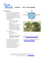
Key Features
•
•
•
•
•
•
•
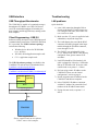
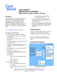
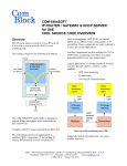
Generic gateway for LAN/TCP-IP, USB
and LVTTL clock synchronous interfaces.
Provides ComBlock assemblies with
standard TCP-IP network connectivity and
direct USB connection to host computer for
both high-speed payload data transfer and
monitoring and control.
TCP-IP interface:
o Role: TCP-IP server, Awaits
remote client(s) connection.
o Supports 3 bidirectional
connections.
o Maximum sustained throughput 53
Mbits/s (100Base-Tx). Actual
speed depends on host computer.
o Standard 100Base-Tx/10Base-T,
RJ-45 connector. Autonegotiation
or manual settings: 10/100 Mbit/s
USB 2.0 interface:
o Role: USB client.
o Supports 2 bidirectional
connections.
o Maximum sustained throughput 85
Mbits/s (USB 2.0 High-Speed).
Actual speed depends on host
computer.
Serial HDLC for interface between bytewise asynchronous connections (USB,
TCP-IP) and bit-serial fixed data rate
connections. Support for two virtual
channels when using TCP-IP.
16Kbits Elastic buffering and flow-control
on each transmit and receive link.
Single 5V supply. Standard 40 pin 2mm
dual row connectors (right, left)
COM-5003
USB Client
SYNCHRONOUS
LVTLL
SYNCHRONOUS
LVTLL
TCP-IP Server
LAN / TCP-IP
For the latest data sheet, please refer to the ComBlock
web site: www.comblock.com/download/com5003.pdf.
These specifications are subject to change without notice.
For an up-to-date list of ComBlock modules, please refer
to www.comblock.com/product_list.htm .
MSS • 18221-A Flower Hill Way • Gaithersburg, Maryland 20879 • U.S.A.
Telephone: (240) 631-1111 Facsimile: (240) 631-1676 www.ComBlock.com
© MSS 2006-2010 Issued 11/30/2010
the data contents is transmitted. No network
information is sent.
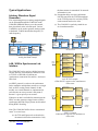
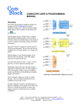
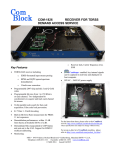
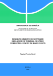
Typical Applications
Arbitrary Waveform Signal
Generation
Files representing binary or analog sampled signals
can be uploaded through the COM-5003 to the
COM-8001 SDRAM memory over the network,
then played back at the selected speed. Various
ComBlocks can be used to generate analog signals
at baseband, 70 MHz intermediate frequency or
radio-frequency.
(b) Propagation delay over the synchronous
link does not affect the TCP-IP throughput
as the TCP-IP protocol is used only locally
on the transmit and receive sides.
(c) The COM-5003 is perfectly suited for use
in a broadcast network.
PC
PC
USB or TCP-IP
USB or TCP-IP
I
COM-5003
TCP-IP /
USB
Gateway
COM-8001
256MB/1GB
DRAM
Storage
Q
clk
COM-2001
Dual
10-bit D/A
Converter
Baseband
Analog
real
COM-5003
TCP-IP /
USB
Gateway
1 or 2 byte-wise
virtual channels
LAN / USB to Synchronous Link
Interface
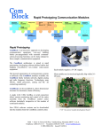
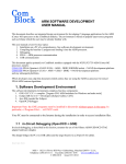
The COM-5003 can be used as a bridge between a
variable data rate (asynchronous) connection such
as TCP-IP or USB and a fixed data rate
(synchronous) connection like satellite / wireless or
cable link.
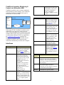
An HDLC protocol is used over the synchronous
link to multiplex multiple data streams over a single
link, in effect creating virtual channels. In this
module, two virtual channels are implemented in
each direction to convey stream 1 and stream 2.
Stream 1 is given priority over stream 2.
Whenever no data is available for transmission, the
HDLC encoder generates empty frames to fill the
synchronous data link. Empty frames are discarded
during HDLC decoding.
Note: The COM-5003 differs from a conventional
router1 in several ways:
(a) the TCP and IP protocols are decoded on
the transmit side before transmission. Only
Synchronous
Modulator
Synchronous
Demodulator
COM-5003
TCP-IP /
USB
Gateway
bit-serial
fixed data rate link
Analog
imaginary
TCP-IP connection
IP Port 1024
Transmit Stream 1
Arbitrary waveform generator,
analog baseband example
1
USB or TCP-IP
1 or 2 byte-wise
virtual channels
PC
Internet
Intranet
LAN
100baseT
RJ-45
TCP-IP connection
IP Port 1026
Transmit Stream 2
TCP-IP connection
IP Port 1024
Receive Stream 1
HDLC
Multiplexing
& Flow Control
ComBlock
Transmitter
Assembly
HDLC
Demultiplexing
ComBlock
Receiver
Assembly
TCP-IP connection
TCP-IP Socket 3
IP Port 1026
Receive Data Stream
Receive Stream 2
TCP-IP
TCP-IP connection
Socket 3
IP
Port 1028
Receive
Data Stream
ComBlock Assembly
Monitoring & Control
ComBlock
Assembly
LAN TCP-IP example
COM-5003-B supports three simultaneous
connections.
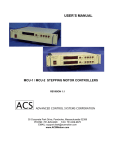
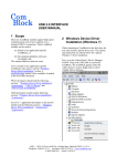
USB connection
Transmit Stream 1
USB
USB 2.0 2.0
Cable
Client
USB connection
Receive Stream 1
HDLC
Multiplexing
& Flow Control
HDLC
Demultiplexing
USB
connection
TCP-IP
Socket 3
ComBlock
Assembly
Receive
Data
Stream
Monitoring & Control
ComBlock
Transmitter
Assembly
ComBlock
Receiver
Assembly
ComBlock
Assembly
USB 2.0 example
COM-5003-A supports two simultaneous
connections.
See also COM-5004 IP Router.
2
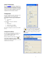
ComBlock Assembly Monitoring &
Control via LAN and/or USB
CLK_IN
Input reference clock for
synchronous I/O. DATA_IN
and SAMPLE_CLK_IN are
read at the rising edge of
CLK_IN. Maximum
frequency: 40 MHz. LVTTL 0
– 3.3V
ComBlock assemblies can be remotely monitored
and controlled by a host computer. The COM-5003
extend the selection of communication types to
include both TCP-IP and USB.
ComBlock
Control
Center (GUI)
Output Signals
USB 2.0 Cable
DATA_OUT[7:0]
COM-5003
TCP-IP
USB
Gateway
or
User
Application
ComBlock
Assembly
SAMPLE_CLK_OUT
Network
TCP-IP
TCP-IP
When using TCP-IP, ComBlock assemblies can be
controlled over an internet or intranet network.
USB’s simple plug&play direct connection to a host
computer can be easier as no network configuration
is needed. Both USB and TCP-IP are supported by
the ComBlock Control Center graphical user
interface, so no programming is needed. Several
ComBlock assemblies can be monitored and
controlled simultaneously from the same computer.
SAMPLE_CLK_OUT_REQ
CLK_OUT
Interfaces
EXT_TRIGGER_OUT
Input Signals
DATA_IN[7:0]
SAMPLE_CLK_IN
SAMPLE_CLK_IN_REQ
Definition
Input signal. The input width
is can be 1-bit or 8-bit under
user control. See control
register REG20. Signals are
pulled-down. LVTTL 0 – 3.3V
Input signal sampling clock.
One CLK_IN-wide pulse.
Read the input signal at the
rising edge of CLK_IN when
SAMPLE_CLK_IN = ‘1’.
Samples can be consecutive.
For example,
SAMPLE_CLK_IN can be
fixed at ‘1’ to indicate that
new input samples are
provided once per CLK_IN
clock period.
Signal is pulled-up.
LVTTL 0 – 3.3V
Input flow control signal
(output). ‘1’ indicates that the
COM-5003 is ready to accept
DATA_IN input samples into
its input elastic buffer. LVTTL
0 – 3.3V. Signal is pulleddown.
Definition
LVTTL 0 – 3.3V output
signal. The output width is
can be 1-bit or 8-bit under
user control. See control
register REG21
LVTTL 0 – 3.3V output
signal sampling clock. One
CLK_OUT-wide pulse.
Read the output signal at the
rising edge of CLK_OUT
when SAMPLE_CLK_OUT
= ‘1’.
Output flow control signal
(input). ‘1’ asks the COM5003 to send DATA_OUT
output data to the next
module. LVTTL 0 – 3.3V.
Signal is pulled-up.
LVTTL 0 – 3.3V 40 MHz
output reference clock.
(from internal oscillator).
25 ns pulse triggered by
software command. See
command register REG22.
Helpful in triggering events
such as COM-8001 start of
data acquisition. LVTTL 0 –
3.3V
Other
Interfaces
Definition
LAN
4 wire. 10Base-T/100Base-TX. RJ45
connector. NIC wiring. Use standard
category 5 cable for connection to a Hub.
Use crossover cable for connection to a
host computer.
USB 2.0
Use USB 2.0 approved cable for
connection to a host computer. Maximum
recommended cable length is 3’.
4.75 – 5.25VDC. Terminal block. Power
consumption is typically 450mA.
USB
Power
Interface
3
Initial Configuration
The static IP address must first be configured over
USB or through adjacent ComBlocks. This network
setting is saved in non-volatile memory. Once the
correct network setting is configured, the Comblock
Control Center and this ComBlock assembly can
communicate over the intranet or internet.
Configuration
An entire ComBlock assembly comprising several
ComBlock modules can be monitored and
controlled centrally over a single connection with a
host computer. Connection types include built-in
types:
• TCP-IP/LAN
• USB
or connections via adjacent ComBlocks:
• USB
• TCP-IP/LAN
• Asynchronous serial (DB9)
• PC Card (CardBus, PCMCIA).
The module configuration is stored in non-volatile
memory.
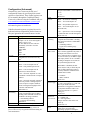
Configuration (Basic)
The easiest way to configure the COM-5003 is to
use the ComBlock Control Center software
supplied with the module on CD.
Then detect the ComBlock module(s) by clicking
Detect button, next click to highlight the
the
COM-5003 module to be configured, next click the
Settings button to display the Settings window
shown below:
Start the ComBlock Control Center, click on the
Communication parameters setup button
and
select USB or LAN/IP as the primary
communication channel. In the latter case, enter the
COM-5003 static IP address.
4
Configuration (Advanced)
Alternatively, users can access the full set of
configuration features by specifying 8-bit control
registers as listed below. These control registers can
be set manually through the ComBlock Control
Center or by software using the ComBlock API (see
www.comblock.com/download/M&C_reference.pdf)
enable
Output
selection
01000 = 8-bit parallel output to J8
10001 = 1-bit serial output to J5 (bidirectional I/O)
Undefined control registers or register bits are for
backward software compatibility and/or future use.
They are ignored in the current firmware version.
IP address
Reserved
Input selection
Configuration
4-byte IP address.
Example : 0x AC 10 01 80 designates
address 172.16.1.128
The new address becomes effective
immediately (no need to reset the
ComBlock).
REG0: MSB
REG1
REG2
REG3: LSB
REG4-19 Reserved for other network
configurations. No need to write any
data.
00000 = J5 connector is disabled
11111 = special case: 1-bit serial output
to COM-7001 FEC encoder through J8.
Bypass
scrambling
Transmit
HDLC enable
00001 = 1-bit serial input from J51
10001 = 1-bit serial input from J8
connector (bi-directional I/O)
11101 = test mode: loopback for 1-bit
serial HDLC-encoded stream. J5 input is
disabled.
Bypass
descrambling
Receive HDLC
1
REG20 bits 4-0
V.34 descrambling of the bit-serial
stream is implemented prior to HDLC
decoding. This command is ineffective
then HDLC decoding is disabled.
0 = descrambling enabled
1 = bypass the descrambling.
REG20 bit 6
Perform HDLC decoding on 1-bit serial
Enabling the bit-wise HDLC is strongly advised to
preserve the bit to byte alignment information during bitserial transmission.
REG21 bits 4-0
V.34 scrambling of the bit-serial stream
is implemented after HDLC encoding.
This control is ineffective when HDLC
is disabled.
0 = scrambling enabled
1 = bypass the scrambling stage.
REG21 bit 6
Perform HDLC encoding on 1-bit serial
receive stream (applicable only when 1bit output serial format is selected
above). When no data is available from
the selected source(s), the HDLC engine
sends empty frames 7E 7E. Use HDLC
encoding to multiplex two streams on
the synchronous physical link.
When HDLC is disabled, the data
source must be ready to fill the IP port
1024 or USB connection in order to
avoid any underflow condition in the
transmit elastic buffers.
01000 = 8-bit parallel input from J5
11110 = test mode. Internally generated
8-bit wide periodic counting sequence
(0-255) as input. J5 input is disabled.
Useful in testing the throughput of the
TCP-IP or USB data link.
00000 = J8 connector is disabled.
00001 = 1-bit serial output to J81
All control registers are read/write.
Parameters
receive stream (applicable only when 1bit input serial format is selected above).
0 = no
1 = yes
REG20 bit 7
COM-8001
external trigger
10Base-T /
100Base-TX
LAN selection
Half/Full
duplex
0 = no HDLC
1 = HDLC enabled.
REG21 bit 7
Special use: Writing to REG22 with a
‘1’ in bit 1 will generate a 1 CLK wide
pulse on pin J8/B6. The main
application is to trigger the COM-8001
file playback/download. There is no
need to reset this bit to ‘0’ prior to
writing a ‘1’.
REG22 bit 1.
00 = 10Base-T
01 = 100Base-TX
10 = Auto negotiation
Changes will take effect at the next
power up.
REG22 bits 3-2
Half-duplex is a safe configuration
which can be used with older
networking equipment. Full duplex
5
results in higher throughput but may be
incompatible with unswitched hubs.
0 = half-duplex
1 = full duplex.
Changes will take effect at the next
power up. REG22 bit 4
Baseline configurations can be found at
www.comblock.com/tsbasic_settings.htm and
imported into the ComBlock assembly using the
ComBlock Control Center File | Import menu.
Monitoring
Monitoring registers are read-only.
Parameters
TCP-IP
connection
HDLC
transmit
elastic
buffers
empty
HDLC
receive
elastic
buffer ¾
full
Number of
transmitted
bytes (USB
or LAN)
Number of
received
bytes (USB
or LAN)
MAC address
Monitoring
Monitors the TCP-IP connections for all
three ports supported.
1 = connected, 0 otherwise.
SREG0 bit 0 port 1024 data stream 1
SREG0 bit 1 port 1026 data stream 2
SREG0 bit 2 port 1028 M&C
‘1’ when an HDLC transmit elastic buffer
is empty, 0 when data transmission is
pending.
SREG0 bit 3: stream 1
SREG0 bit 4: stream 2
‘1’ when an HDLC receive elastic buffer
is more than ¾ full, ‘0’ otherwise.
SREG0 bit 5: stream 1
SREG0 bit 6: stream 2
Total number of payload data bytes
received from LAN or USB and
forwarded to an external digital device
(excludes monitoring & control
messages, includes all virtual data
streams). 32-bit byte count. Counter rolls
over when reaching 0xFFFFFFFF.
SREG1: bits 7-0 (LSB)
SREG2: bits 15-8
SREG3: bits 23-16
SREG4: bits 31-24 (MSB)
Total number of payload data bytes
received from an external digital device
and forwarded to LAN / USB (excludes
monitoring & control messages, includes
all data virtual streams). 32-bit byte
count. Counter rolls over when reaching
0xFFFFFFFF.
SREG5: bits 7-0 (LSB)
SREG6: bits 15-8
SREG7: bits 23-16
SREG8: bits 31-24 (MSB)
Unique 48-bit hardware address (802.3).
In the form
SREG9:SREG10:SREG11:…:SREG14
As the monitoring data is constantly changing, it is
important to be able to prevent changes while
reading a multi-byte parameter. The monitoring
data is latched upon reading register 0. Therefore,
register 0should always be read first.
6
Test Points
Test points are provided for easy access by an
oscilloscope probe. The main focus of these test
points is to help monitor proper flow control
operation.
Test
Point
Definition
TP 1
TCP-IP connection on port 1024 (stream 1)
1 = connected, 0 otherwise
TCP-IP connection on port 1026 (stream 2)
1 = connected, 0 otherwise
TCP-IP connection on port 1028 (Monitoring &
Control)
1 = connected, 0 otherwise
Stream 1 HDLC transmit elastic buffer empty
TP 2
TP 3
TP 4
Operation
Concept
The COM-5003 converts a TCP-IP socket stream or
a USB stream into a simple clock-synchronous data
stream and vice versa.
Using TCP-IP:
On the transmit side, the COM-5003 decodes the
TCP-IP protocol and extracts the data from the
network client. TCP, IP and Network information,
and in particular routing information, are not
transmitted from one end to the other.
1 = empty, 0 otherwise
TP 5
Stream 2 HDLC transmit elastic buffer empty
1 = empty, 0 otherwise
TP 6
Stream 1 HDLC receive elastic buffer ¾ full
1 = ¾ full, 0 otherwise
TP 7
Stream 2 HDLC receive elastic buffer ¾ full
1 = ¾ full, 0 otherwise
TP 8
TP 9
TP 10
INIT#
DONE
At the receiving end, the network client must first
connect to the COM-5003 to receive data.
HDLC flag 7E detected at input
CRC error detected on channel 1 HDLC frame.
1 = error detected at end of frame, 0 = no error
CRC error detected on channel 2 HDLC frame.
1 = error detected at end of frame, 0 = no error
Internal processing clock divided by 8.
5 MHz square wave.
1 when the FPGA is loaded with a valid .mcs
configuration file (typically 0.4 seconds after power
up).
The COM-5003 maintains the flow-control
information between the TCP-IP socket and the
input/output interfaces. For example, if the COM5003 is connected to a COM-1001 QPSK
modulator configured for 1 Mbit/s data throughput,
the network client (i.e. data source) will be asked
for 1 Mbit/s throughput over the TCP-IP link.
Using USB:
USB and TCP-IP can be used interchangeably and
independently at the transmit-end or receive-end.
For example, the user can select TCP-IP on the
transmit side while using USB on the receiving end.
The main functional difference is that the COM5003 USB interface supports only one bi-directional
stream whereas the TCP-IP interface supports two
streams.
7
Connectivity
As a gateway, the COM-5003 interconnects TCPIP, USB and clock synchronous LVTTL interfaces.
Some connections are configured by control
registers (see configuration registers), while others
are configured by selecting an FPGA option, as
described below.
To select the –A or –B option, please follow the
three steps:
Step 1: from the ComBlock Control Center
graphical user interface, enumerate the ComBlocks,
highlight the COM-5003 and open the personalities
windows by clicking on the swiss army knife
button.
Option –A
Monitoring and Control is performed through either
TCP-IP (IP port 1028) or USB, at the user’s
discretion.
A single high-speed bi-directional data channel is
supported through USB.
The user can select several formats (8-bit parallel
mode, 1-bit serial with HDLC, 1-bit serial without
HDLC) at the input and output connectors through
control registers.
USB 2.0
USB Client
Step 2: pull-down the personalities index and select
index 2 for option –A or 3 for option –B.
Step 3: push the “Set Default” button.
8
8
SYNCHRONOUS
LVTLL
J5
1
1
8-bit
parallel
to bit
serial
bit-serial
to 8-bit
parallel
ch1
ch1
serial
HDLC
decoder
1-ch
serial
HDLC
encoder
1-ch
1
SYNCHRONOUS
LVTLL
J8
1
Option –A data path
Option –B
All communications are established exclusively
through the TCP-IP server. The USB Client is
disabled.
The TCP-IP server supports three simultaneous
connections: 2 high-speed bi-directional data
channels and one bi-directional monitoring and
control channel.
The user can select several formats (8-bit parallel
mode, 1-bit serial with HDLC, 1-bit serial without
HDLC) at the input and output connectors through
control registers.
Network
It takes 0.4 seconds to switch between options
under user control.
1026
1024
1024
1026
TCP-IP Server
8
8
SYNCHRONOUS
LVTLL
J5
1
8-bit
parallel
to bit
serial
bit-serial
to 8-bit
parallel
ch1
1
serial
HDLC
decoder ch2
2-ch
ch1
ch2
serial
HDLC
encoder
2-ch
Option –B data path
8
1
SYNCHRONOUS
LVTLL
J8
1
Format Conversion
Parallel to serial conversion occurs at the output
when a 8-bit byte received over the TCP-IP or USB
link is converted to one-bit serial when so
configured by the user. The key rule for parallel to
serial conversion is that the most significant bit
(MSb) is transmitted first.
Likewise, in the serial-to-parallel conversion which
may be implemented at the input, the first received
bit is placed at the MSb position in the byte.
The maximal frame length (before accounting for
bit stuffing) is 1024 bytes of information plus 5
bytes of overhead.
The following bit-stuffing mechanism is used on
the transmit side for all fields except the opening
and closing flags: a ‘0’ is inserted after five
consecutive 1’s.
The address field is used to indicate the type of data
conveyed within:
01: data from IP port 1024
02: data from IP port 1026
Serial HDLC
A bit-serial HDLC format can be used to convey
data over a synchronous serial link such as a
wireless or satellite link. The HDLC objective is
three-fold:
(a) Tell the receiver side when no information
is available for transmission.
(b) Implement multiple virtual channels over a
common physical link.
(c) Recover the original bit-to-byte alignment
of the original USB or TCP-IP connection
at the receiving end.
HDLC can be enabled or disabled under user
control. See control registers REG21 and REG22.
This section provides details as to the serial HDLC
format used on the synchronous serial link. It is
intended for developers and can be skipped by most
users.
1 byte 1 byte
opening
flag
Information Field
variable-length
A loop back mode is provided for system-level test
purposes. Transmitted data are looped back into the
1-bit serial input. The nominal input pins are
disabled. However, the nominal output pins are
enabled. Be sure to configure the output format as
‘1 bit serial with HDLC’.
The loopback test mode can be used in conjunction
with USB (1 channel) and TCP-IP (2 channels).
TCP-IP connection
IP Port 1024
Transmit Stream 1
Internet
Intranet
LAN
100baseT
RJ-45
TCP-IP connection
IP Port 1026
Transmit Stream 2
TCP-IP connection
IP Port 1024
Receive Stream 1
ComBlock
Transmitter
Assembly
HDLC
Multiplexing
& Flow Control
HDLC
Demultiplexing
ComBlock
Receiver
Assembly
TCP-IP connection
TCP-IP Socket 3
IP Port 1026
Receive Data Stream
Receive Stream 2
Serial HDLC format
7E Address
Field
Loop Back
FCS
2 bytes
CRC16
7E
1 byte
closing
flag
Data is encapsulated within variable length frames
starting and ending with a 0x7E flag. A two-byte
CRC check can be used to verify if the frame is
error free.
The information field always contain an integer
number of bytes. The most significant bit is
transmitted first.
TCP-IP
TCP-IP connection
Socket 3
IP Port 1028
Receive
Data Stream
ComBlock Assembly
Monitoring & Control
ComBlock
Assembly
Trigger Pulse
Users can remotely generate a short (25ns) pulse to
trigger external devices such as the COM-8001
arbitrary waveform generator. The
EXT_TRIGGER_OUT pulse is generated on pin
J8/B6 upon sending control register REG22 with bit
1 set to ‘1’.
Recovery
The COM-5003 is protected against corruption by
an invalid FPGA configuration file or an invalid
user configuration. To recover from such
occurrence, connect the BOOT pin to the nearby
ground pin using a jumper and power-up the COM9
5003. Remove the jumper after 1 second. The
COM-5003 will be automatically configured with a
boot configuration which restores both USB and
LAN/TCP-IP communications. This boot file is unerasable. Once this is done, the user can safely
restore the user configuration and/or re-load a valid
FPGA configuration file into flash memory using
the ComBlock Control Center.
TCP-IP Interface
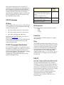
Throughput tests conditions
Client: Intel Pentium 4 2.8 GHz running
winsock-based console application. Direct
cross-over LAN cable. No other application
running.
COM-5003 configured as ‘Auto
Negotiation”. 100Base-Tx connection.
Client: AMD Sempron 3000
Direct cross-over LAN cable.
Client: Intel Pentium 4 2.8 GHz over LAN
(through two LAN switches)
Throughput
(100MB
average)
53 Mbits/s
47 Mbits/s
32 Mbits/s
IP Ports
While configured in option –B, the COM-5003 acts
as a TCP-IP server. As such it opens the following
sockets in listening mode:
•
Port 1024: transmit and receive data stream 1.
•
Port 1026: transmit and receive data stream 2.
•
Port 1028: monitoring and control port.
In addition, the COM-5003 opens port 1029 as a
UDP port for remote reset.
While configured in option –A, the COM-5003 acts
as a TCP-IP server for remote monitoring and
control only (port 1028).
TCP-IP Throughput Benchmarks
The COM-5003 is capable of a sustained (average)
throughput of 53 Mbits/s over 100base-Tx. In most
cases, the sustained throughput is limited by the
TCP-IP client computer, the application(s) running
on the client computer and the network
configuration, as illustrated in the one-way data
transfer benchmarks below:
IP Protocols
This module supports the following IP protocols:
- Ping
- ARP
- TCP-IP
Power Up
The LAN link is available typically 2.1 seconds
after power up.
Ping
The module responds to ping requests with size up
to 470 bytes. Ping can be used to check the module
response over the LAN network. Ping can be used
at any time, concurrently with other transmit and
receive transactions. For example, on a Windows
operating system, open the Command prompt
window and type “ping –t –l 470 172.16.1.128” to
send pings forever of length 470 bytes to address
172.16.1.128.
UDP-IP
Port 1029 is open as a UDP receive-only port. This
port serves a single purpose: being able to reset all
TCP-IP connections gracefully. This feature is
intended to remedy a common practical problem: it
is a common occurrence for one side of a TCP-IP
connection to end abnormally without the other side
knowing that the connection is broken (for example
when a server ‘crashes’). In this case, new
connections cannot be established without first
closing the previous ones. The problem is
particularly acute when the COM-5003 is at a
remote location.
10
The command “@001RST<CR><LF>” sent as a
UDP packet to this port will reset all TCP-IP
connections within the COM-5003.
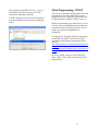
TCP-IP connections can also be cleared remotely
from the ComBlock Control Center as illustrated
below:
Client Programming : TCP-IP
This section is intended to help designers who want
to design their own client application. It can be
skipped by users of ready-to-use applications such
as Hyperterminal, ComBlock Control Center, etc.
In network terminology, the COM-5003 is a server.
It awaits connection establishment and connection
termination under the initiation of clients. It never
initiate any connection establishment or
termination.
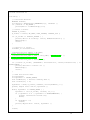
An example of C-language Winsock programming
for Windows OS clients is shown below. More
information about Winsock programming can be
found at
http://msdn.microsoft.com/library/default.asp?url=/l
ibrary/enus/winsock/winsock/finished_server_and_client_co
de.asp
Be sure to include a reference to the Winsock2
library (WS2_32.lib) in the project release and/or
debug settings.
11
#include <stdio.h>
#include "winsock2.h"
void main() {
// Initialize Winsock.
WSADATA wsaData;
int iResult = WSAStartup( MAKEWORD(2,2), &wsaData );
if ( iResult != NO_ERROR )
printf("Error at WSAStartup()\n");
// Create a socket.
SOCKET m_socket;
m_socket = socket( AF_INET, SOCK_STREAM, IPPROTO_TCP );
if ( m_socket == INVALID_SOCKET ) {
printf( "Error at socket(): %ld\n", WSAGetLastError() );
WSACleanup();
return;
}
// Connect to a server.
sockaddr_in clientService;
clientService.sin_family = AF_INET;
// insert destination address below
clientService.sin_addr.s_addr = inet_addr( "172.16.1.128" );
// insert destination port below
clientService.sin_port = htons(1024);
if ( connect( m_socket, (SOCKADDR*) &clientService, sizeof(clientService) ) ==
SOCKET_ERROR) {
printf( "Failed to connect.\n" );
WSACleanup();
return;
}
// Send and receive data.
int bytesSent;
int bytesRecv = SOCKET_ERROR;
char sendbuf[32] = "Client: Sending data.";
char recvbuf[32] = "";
bytesSent = send( m_socket, sendbuf, strlen(sendbuf), 0 );
printf( "Bytes Sent: %ld\n", bytesSent );
while( bytesRecv == SOCKET_ERROR ) {
bytesRecv = recv( m_socket, recvbuf, 32, 0 );
if ( bytesRecv == 0 || bytesRecv == WSAECONNRESET ) {
printf( "Connection Closed.\n");
break;
}
if (bytesRecv < 0)
return;
printf( "Bytes Recv: %ld\n", bytesRecv );
}
return;
}
12
USB Interface
Troubleshooting
USB Throughput Benchmarks
LAN problems
The COM-5003 is capable of a sustained (average)
throughput of 85 Mbits/s over USB 2.0. In most
cases, the sustained throughput is limited by the
host computer and the application(s) running on the
host computer.
Quick checklist:
Client Programming : USB 2.0
Software to help developers create USB high-speed
communications between the COM-5003 and a host
PC is provided. The USB 2.0 software package
includes the following:
•
Windows device driver for XP/2000/Me
(.sys, .inf files)
•
Java API, .dll and application sample code
•
C/C++ application sample code
The USB 2.0 software package is available in the
ComBlock CD and can also be downloaded from
ComBlock.com/download/usb20.zip.
The user manual is available at
ComBlock.com/download/USB20_UserManual.pdf
Java app.
API
C/C++
application
.dll
Driver
PC Operating System
PC Hardware
1) is the LAN connection through a Hub or
directly to the host PC? In the former case,
use a straight LAN cable, in the latter case
use a cross-over cable.
2) Make sure the +5V power is applied to both
submodules, not just the larger one.
3) The LAN adapter (the one with the RJ-45
connector) should be plugged in the larger
module through the J9 bottom connector,
never through J5 or J8.
4) The ‘DONE’ test point should be high
(2.5V), otherwise the FPGA is not properly
configured. If not, please contact us for
assistance.
5) Link LED should be ON when the LAN
cable is plugged in. Likewise, a LED at the
Hub or PC should be ON. If not, the cable
could be bad or see points 1 – 4 above.
6) Did you assign a static IP address to the
COM-5003? Please see the “Initial
configuration” section on page 4.
7) Do not assign the same IP address for the
COM-5003 and the host computer.
8) Is the COM-5003 IP address consistent
with the PC address? In general the first 3
numbers of the IP address must match
9) If ping does not work, see points 5 – 8
above.
USB
COM-5003
Blue: supplied hardware
Green: supplied ready-to-use software
Yellow: source code examples
13
Input data is read at
the rising edge of CLK_IN
Timing
Clocks
The clock distribution scheme embodied in the
COM-5003 is illustrated below.
60 MHz
low-jitter clock
from USB PHY
CLK_IN
SAMPLE_CLK_IN
DATA_IN
FPGA
DLL
xM/N
CLK_IN*
SAMPLE_CLK_IN
DATA_IN
Dual
Port
RAM
CLK_P
synchronous
processing
clock
80 MHz typ.
DLL
xK/L
Dual
Port
RAM
Best time to generate data
at the source is at the
falling edge of CLK_IN
CLK_OUT* (40 MHz)
SAMPLE_CLK_OUT
DATA_OUT
Output
Output data is generated at
the falling edge of CLK_OUT
(*) denotes edge-trigger signal
Baseline clock architecture
Green = 80 MHz processing zone
Light blue = user defined input clock
Dark blue = 40 MHz output clock
Input:
The input signals at the J5 connector are
synchronous with the CLK_IN clock at J5/A1. This
clock can be up to 40 MHz.
A 16Kbit dual-port RAM elastic buffer is used at
the boundary between inputs and internal
processing area. Thus, the input clock frequency
can be independent from the internal processing
clock frequency.
Output:
The 40 MHz output clock CLK_OUT is locked to
the internal USB PHY 60 MHz clock by means of a
DLL. CLK_OUT is not related in frequency to the
external CLK_IN clock.
CLK_OUT
SAMPLE_CLK_OUT
DATA_OUT
Best time to read data
is at the rising edge
of CLK_OUT
LEDs
2 LEDs located close to the LAN RJ-45 jack
provide summary information as to the LAN: Link
and activity.
The output signals are synchronous with the rising
edge of the 40 MHz reference clock CLK_OUT
(i.e. all signals are stable at the rising edge of the
reference clock CLK_OUT).
Internal processing:
The core signal processing performed within the
FPGA is synchronous with the 80 MHz processing
clock CLK_P. The processing clock is derived from
the USB PHY 60 MHz oscillator. CLK_P is not
related to the external CLK_IN clock.
Input
14
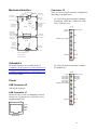
Connector J5
Mechanical Interface
type 'B' USB receptacle
right corner
left corner
Board Corner
(2.040", 3.160")
(1.560", 3.160")
(3.000", 3.000")
5VDC Power
Terminal
USB
Block, 90 deg
Mounting hole
J2
(2.840", 2.840")
GND
+5V
J1
J3
Test points (J6)
1
10
A1 pin (2.900", 2.250")
Digital Outputs
J5
J8
2 rows x 20 pin
INIT
J7
DONE
+3.3V
BOOT
male, 90 deg
Top view
GND
JTAG
Mounting hole
(0.160",2.840")
There are several possible connector configurations,
depending on the application:
A1 pin (0.100", 2.250")
A1
B1
B1
A1
A1
A20
B20
B20
A20
Mounting hole
(0.160",0.160")
B1
Analog/Digital I/O
2 rows x 20 pin
female, 90 deg
(a) 1-bit wide input from another ComBlock
[COM-1009, COM-7001, COM-1202, COM1418, COM-1027, etc]
CLK_IN
DATA_IN
SAMPLE_CLK_IN
J9
Board Corner
(0.000", 0.000")
Mounting hole
(0.160",-0.390")
B20
A20
B1
A1
A20
B20
A1
B1
Mounting hole
(2.840", 0.160")
GND
(2.840",-0.390")
J2
SAMPLE_CLK_IN_REQ
Top view
J1
LED Activity
U2
GND
LED Link
+5V
5VDC Power
Terminal
Block, 90 deg
Mounting hole
(0.160",-2.070")
RJ-45
(2.050",-2.230")
LAN
Connector
(1.420",-2.230")
GND
Mounting hole
(2.840", -2.070")
Corner
(3.000", -2.230")
GND
Mounting hole diameter: 0.125"
A1 pin height: 0.039"
M&C RX
M&C TX
Maximum height 1.100"
GND
A20
B20
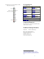
Schematics
A1
Pinout
(b) 8-bit wide input from another ComBlock
[COM-8002,etc]
B1
The board schematics are available on-line at
ComBlock.com/download/com_1400schematics.zip
for the main board and
ComBlock.com/download/com_5002schematics.zip
for the LAN adapter.
CLK_IN
DATA_IN(0)
DATA_IN(2)
DATA_IN(4)
DATA_IN(6)
DATA_IN(7)
SAMPLE_CLK_IN_REQ
SAMPLE_CLK_IN
DATA_IN(1)
DATA_IN(3)
DATA_IN(5)
GND
USB Connector J2
USB type B receptacle.
GND
LAN Connector J1
The RJ-45 Jack is wired as a standard PC network
interface card. Connection to a LAN Hub is over a
straight-through cable.
1
GND
M&C RX
M&C TX
8
GND
A20
B20
1 Tx+
2 Tx3 Rx+
6 Rx-
RJ-45 Jack
15
(c) Bi-directional connection (input and output
through a single connector)
(b) 8-bit wide output to another ComBlock
[COM-8001, etc]
A1
B1
SAMPLE_CLK_IN
B1
A1
CLK_IN
DATA_IN
CLK_OUT
DATA_OUT(0)
DATA_OUT(2)
DATA_OUT(4)
DATA_OUT(6)
DATA_OUT(7)
SAMPLE_CLK_OUT_REQ
GND
SAMPLE_CLK_IN_REQ
SAMPLE_CLK_OUT
DATA_OUT(1)
DATA_OUT(3)
DATA_OUT(5)
GND
EXT_TRIGGER_OUT
GND
SAMPLE_CLK_OUT
CLK_OUT
DATA_OUT
GND
GND
GND
SAMPLE_CLK_OUT_REQ
M&C RX
RESERVED
RESERVED
M&C TX
RESERVED
GND
M&C TX
M&C RX
Connector J8
B1
A1
CLK_OUT
DATA_OUT
B1
(a) 1-bit wide output to another ComBlock
[COM-1010, COM-1402, COM-1019, COM1028, etc]
(c) Bi-directional connection (input and output
through a single connector)
A1
There are several possible connector configurations,
depending on the application:
B20
A20
A20
B20
GND
CLK_OUT
DATA_OUT
SAMPLE_CLK_OUT
GND
EXT_TRIGGER_OUT
SAMPLE_CLK_OUT_REQ
SAMPLE_CLK_OUT
GND
EXT_TRIGGER_OUT
GND
SAMPLE_CLK_IN
CLK_IN
DATA_IN
SAMPLE_CLK_OUT_REQ
GND
GND
SAMPLE_CLK_IN_REQ
M&C TX
RESERVED
RESERVED
M&C RX
RESERVED
GND
B20
A20
GND
M&C TX
M&C RX
GND
B20
A20
16
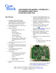
(d) Special case: 1-bit serial output to a COM7001 turbo code encoder.
A1
B1
CLK_OUT
SAMPLE_CLK_OUT
DATA_OUT
GND
SAMPLE_CLK_OUT_REQ
GND
GND
M&C TX
M&C RX
I/O Compatibility List
(not an exhaustive list)
Input
COM-1202
PSK/QAM/APSK modem
Output
COM-1402
PSK/QAM/APSK
modulator
COM-1418 DSSS
COM-1019 DSSS
Demodulator
Modulator
COM-1027 FSK/MSK
COM-1028
demodulator
FSK/MSK/GFSK/GMSK
modulator
COM-1009A Viterbi
COM-1010 Convolutional
decoder K=7
encoder
COM-8002 Data
COM-8001 Arbitrary
acquisition module
Waveform Generator
COM-7002 Turbo code encoder/decoder
COM-1200/1300/1400 FPGA development platforms
COM-1600/1500 FPGA + ARM development platforms2
GND
A20
B20
Configuration Management
This specification is to be used in conjunction with
VHDL software revision 8.
ComBlock Ordering Information
COM-5003
TCP-IP / USB Gateway
MSS • 18221-A Flower Hill Way •
Gaithersburg, Maryland 20879 • U.S.A.
Telephone: (240) 631-1111
Facsimile: (240) 631-1676
E-mail: [email protected]
2
98-pin to 40-pin adapters to interface with other
Comblocks are supplied free of charge. Please let us
know about your interface requirements at the time of
order.
17