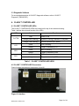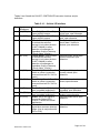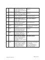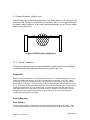
1
5.2 Electrical
5.2.1 Wiring Harness - Connections
Although the CLASS™ I/O requirements are well-defined, differences in bus wiring,
types of controllers, polarities, etc. all contribute to the fact that each type of bus must be
carefully assessed to ensure that the requirements of the I/O are correctly fulfilled.
The following section describes the input, output, and power interface for the CLASS™
controller and provides a description of requirements and alternatives.
1. DEFINITIONS
1.1 Active: the “active” state of a signal is the state when the event of
interest occurs. It is usually described by the name of the signal. As an
example, for the “Fully Open” signal, the active state occurs when the
door is fully open. When the door is not fully open, the signal is not active.
1.2 High-going: a signal is high-going when it is connected to a positive
voltage (usually 24V) when it is active. (When it is not active it may be
connected to GND or it may be open.) A signal which is high-going when
active is also called an active-high signal.
1.3 Low-going: a signal is low-going when it is connected to GND when it
is active. (When it is not active it may be connected to a high voltage or it
may be open.) A signal which is low-going when active is also called an
active-low signal.
Notes: All signal names below are as used on the CLASS™ interface
harness, and are in bold. [Non-standard connections are in brackets.]
2. INPUTS
2.1 Input Signals
For the standard CLASS™ installation, inputs may be high-going or lowgoing when active. The appropriate input must be used for each case.
2.1.1. IN1 (DFO) - this input must be high when the door is fully open, and
low or open otherwise. This signal is usually provided by a switch or
proximity sensor on the baseplate. If a switch is used, make sure it closes
to system high voltage when the door is fully open, and is open otherwise.
If a proximity sensor is used, make sure that it is a PNP sensor. If an NPN
sensor is used, or the switch connects to GND when the door is fully
open, use /IN1 (/DFO) instead.
2.1.2. IN2 (DAI) – If IN2 becomes high when the door is not in operation,
the sensor(s) will be turned on for use as a “drunk alarm”. This input is
used together with OUT2, which will provide target detection status for the
MRN 03002-8 TB08-03-192
Page 22 of 34