1
Santa Clara University
DEPARTMENT of COMPUTER ENGINEERING
DEPARTMENT of ELECTRICAL ENGINEERING
Date: June 5, 2003
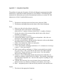
I HEREBY RECOMMEND THAT THE THESIS PREPARED UNDER MY
SUPERVISION BY
Lemuel Diaz, Michelle Enyeart, Kristen Kristich, and Alan Moore
ENTITLED
Formation Robots
BE ACCEPTED IN PARTIAL FULFILLMENT OF THE REQUIREMENTS FOR THE
DEGREE OF
BACHELOR OF SCIENCE IN COMPUTER ENGINEERING
BACHELOR OF SCIENCE IN ELECTRICAL ENGINEERING
______________________
______________________
THESIS ADVISOR
THESIS ADVISOR
______________________
______________________
DEPARTMENT CHAIR
DEPARTMENT CHAIR
Formation Robots
by
Lemual Diaz
Michelle Enyeart
Kristen Kristich
Alan Moore
SENIOR DESIGN PROJECT REPORT
Submitted in partial fulfillment of the requirements
for the degree of
Bachelor of Science in Computer Engineering
Bachelor of Science in Electrical Engineering
School of Engineering
Santa Clara University
Santa Clara, California
June 5, 2003
ii
Abstract
From science fiction to advanced research, robot technology has been fascinating
the human intellect for years. Advances in technology over the past few years have
allowed for many new developments in the growing field. One small but important area
of research involves controlling multiple robots working together towards a single goal.
Our project seeks to do just that, utilizing several sensing technologies together to create
a system that controls a formation as it navigates from one destination to another.
A single robot can do a lot of things that human beings cannot, but the capability
to control a group of robots as a single formation dramatically increases the possibilities.
However, controlling a group of robots has its own difficulties. The goal of this project is
to explore the potential of formation control with regards to the control strategy, the
different possible sensors, and the ability to make it all user-friendly with a graphical
interface. Additionally, the project aims to have a number of robots move in a formation
from one location to another. The project successfully controlled a system of robots with
linear, autonomous capabilities.
iii
Acknowledgements
Formation Robots would like to give a special thanks to our advisors Professor
Chris Kitts and Dr. Neil Quinn for their enthusiasm and outstanding support over the
duration of our project.
Formation Robots would also like to thank Bob Dougherty for his commitment to
the success of our project.
This project would not have been possible without the funding and support
provided by various foundations and companies. We would like to thank The Santa
Clara University Steering Committee, the National Science Foundation, and the Santa
Clara University Alumni Board for allotting funds which allowed for the acquisition of
the necessary hardware. A special thanks also goes out to Lockheed Martin for the usage
of their Ultra Wide Band Units, and to ActivMedia Robotics for all of their technical
support over the duration of the year.
This material is based upon work supported by the National Science Foundation
under Grants No. 0079875 and No. 0082041. Any opinions, findings, and conclusions or
recommendations expressed in this material are those of the author(s) and do not
necessarily reflect the views of the National Science Foundation.
iv
Table of Contents
List of Figures
Chapter 1
vii
Introduction
1
1.1
Motivation
1
1.2
Goals
2
System Overview
4
The Robots
5
2.1.1 Software
8
2.1.2 Sonar
8
2.1.3 Maintenance and Problems
9
Instrumentation
10
Ultra Wideband
10
3.1.1 Pulse Modulation
10
3.1.2 Interference Issues
11
3.1.3 Applications in our Project
11
Chapter 2
2.1
Chapter 3
3.1
3.1.3.1 Relative Distance
12
3.1.3.2 Angle of Arrival
12
3.1.3.3 Additional Applications
12
3.1.4 Advantages and Disadvantages
13
3.2
Digital Compass
13
3.3
Power Supplies
15
3.3.1 UWB
15
3.3.2 Hub
16
Control
17
4.1
Programming Environment
17
4.2
Connecting to the User Interface
18
4.3
Behaviors
18
4.4
Implemented Behaviors
20
4.4.1 Lead Robot
20
Chapter 4
4.4.1.1 The Go-To Behavior
20
4.4.1.2 The Avoid Obstacles Behavior
21
v
4.4.2 Following Robot
23
4.4.2.1 The Maintain Distance Behavior
23
4.4.2.2 The Maintain Angle Behavior
24
4.4.3 Behavior Extendibility
25
4.5
Overall Control Function
25
4.6
Getting into Formation
26
4.7
ARIA
26
Graphical User Interface (GUI)
28
5.1
Software Tools and Components
28
5.2
Interface
29
5.3
Future Work
31
Implementation and Test
32
6.1
Long Range Testing
32
6.2
Formation Testing
32
Professional Issues
34
7.1
Social
34
7.2
Political
34
7.3
Economic
34
7.4
Health and Safety
34
7.5
Manufacturability
35
7.6
Sustainability
35
7.7
Environmental Impact
35
7.8
Usability
36
7.9
Lifelong Learning
36
7.10
Compassion
37
Conclusion
38
8.1
Summary
38
8.2
Contributions
38
8.3
Future Extensions
38
8.4
Lessons Learned
39
Digital Compass Code
40
Chapter 5
Chapter 6
Chapter 7
Chapter 8
Appendix A
vi
Appendix B
Control Code
43
B.1
Database Access Code
43
B.2
Leading Robot Implementation
47
B.3
Go-To Behavior Implementation
53
B.4
Obstacle Avoidance Implementation
64
B.5
Following Robot Implementation
74
B.6
Maintain Distance Behavior Implementation
77
B.7
Maintain Angle Behavior Implementation
93
Appendix C
Assignment Algorithm Details
113
Appendix D
User Database Details
114
D.1
Creating the Necessary Structures
114
D.2
FormationRobots Tables
114
Graphical User Interface Code
116
E.1
Code for Formation Choice Page
116
E.2
Code for Chosen Formation Page
118
E.3
Code to Accept User Input
120
E.4
Code to Write to Database
122
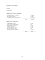
Appendix F
Project Budget
124
Appendix G
User Manual
125
Appendix E
References
132
vii
List of Figures
1-1
Terrain Mapping
1
1-2
Formation
2
2-1
System Components
4
2-2
Pioneer's turning velocity profile
5
2-3
Old Pioneer Microcontroller
6
2-4
Old Pioneer Motor-Driver Board
7
2-5
New Pioneer Microcontroller
7
2-6
New Pioneer Motor-Drive Board
8
2-7
Front Sonar Array
9
3-1
Pulse Modulation
10
3-2
Dual Antenna Configuration
12
3-3
CMPS01 Electronic Compass
14
3-4
Stamp & Compass Schematic
14
3-5
UWB Power Pack
15
3-6
Hub Power Pack
16
4-1
Overview of System Control
17
4-2
Illustration of Behavior Vectors
18
4-3
Behavioral Gain Factors
19
4-4
The Go-To Behavior
20
4-5
The Obstacle Avoidance Behavior
21
4-6
Adjustment of Obstacle Detection for Other Robots
22
4-7
The Maintain Distance Behavior
23
4-8
The Maintain Angle Behavior
24
5-1
Excerpt from Formations Table
29
5-2
GUI: Choose a Formation Page
29
5-3
GUI: Select Distance Page
30
5-4
GUI: Interactive Page
31
6-1
Test Layout
32
6-2
Long Range Results
32
viii
6-3
No Wall Test Results
33
6-4
With Wall Test Results
33
6-5
Wall vs. No Wall
33
ix
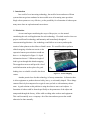
1. Introduction
In a world of ever increasing technology, the need for better and more efficient
systems that can go into uncharted or inaccessible areas is becoming more prevalent.
Single robot systems are very effective, yet the possibility for a formation of robots opens
many more doors to exploration and convenience.
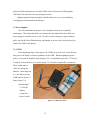
1.1 Motivation
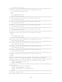
As our team began considering the scope of the project, we also started
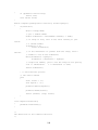
considering the real world applications for such technology. We asked ourselves how our
project could benefit technology and humanity and immediately thought of
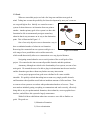
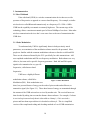
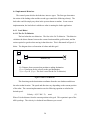
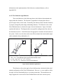
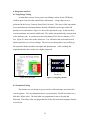
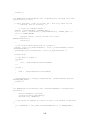
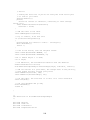
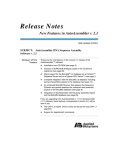
extraterrestrial applications. Our technology would allow us to survey and map the
terrain of other planets such as Mars or Earth’s moon. We would be able to perform
altitude mapping of unknown terrain so that
expensive human space missions would not
have to. As displayed in Figure 1-1 depth
information about a 13 Kilometer length of
land is given through this altitude mapping.
The mapped out areas would provide a lot of
useful information such as places for good
landing sites or valuable scientific data about
Figure 1-1 Terrain Mapping
craters.
Another practical use for this technology is factory automation. In factories there
is often equipment or products that are bulky, heavy, or awkwardly shaped. These things
cannot effectively be transported on a typical conveyor belt or with stationary robotic
arms. A good solution to this problem is using the robots to move such objects. A
formation of robots could be formed specifically to the parameters of the object and
transported through the factory, all the while avoiding other workers and equipment.
This could essentially save a company a lot of the time and man power that would
otherwise be done manually.
1
1.2 Goals
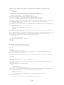
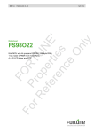
When we started this project we had a few long term and short term goals in
mind. Taking into account the possibility for future development by next year’s team we
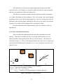
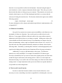
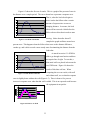
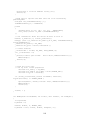
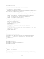
set our goals high at first. Initially we wanted to create a
system of robots that move in formation from one point to
another. Another primary goal of our system is to have this
formation be able to autonomously navigate around any
obstacles that it may encounter on its way to the destination
point. This is illustrated in Figure 1-2.
One of our early objectives was to determine a way to
have an unlimited number of robots in our formation.
Removing this constraint from our system would give us a
Figure 1-2 Formation
wide range of new possibilities such as ad hoc networks,
which would theoretically allow us to communicate over any physical distance.
Navigating around obstacles was a crucial portion of the overall goals of this
project. We wanted to take into account all possible obstacles and their positions.
Autonomy, although not critical to the functionality of our system, was one of our
main goals. We wanted the user to be able to plug in a destination into the user interface
and the formation gets there without any further necessary intervention.
As our project progressed our goals were redefined to fit a more suitable
timetable. We quickly realized that taking into account every single possible obstacle
and formation related problem would take an inordinate amount of effort and time. Thus
we narrowed our system to two robots with predetermined markers of success. These
new markers included: getting everything to communicate and work correctly, effectively
being able to stay in a predetermined formation, detect obstacles, create a graphical user
interface, and still have this system be largely autonomous.
With all of these redefinitions taken into account we were able to finalize our
goals. The goals are:
1) Maintain a Formation
2) Get to a destination
2
3) Avoid Obstacles
4) Autonomous System
3
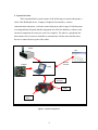
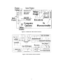
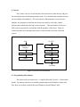
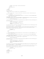
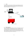
2. System Overview
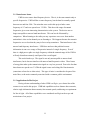
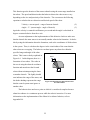
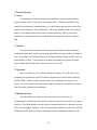
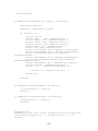
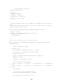
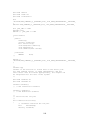
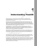
The Formation Robot system consists of the following seven main subsystems: a
robot, Ultra Wideband device, Compass, Graphical User Interface, wireless
communication subsystem, a software control subsystem, and a Laptop. Each subsystem
was independently designed and then integrated once all of the hardware, software, and
electrical components necessary for each were complete. The robot is a purchased unit
that consists of its own micro-controller to communicate with the sonar and the motor
drivers to control the drive path of the robots.
UWB
GUI
Wireless
Network
Compass
Laptop
Robot
Processor
Sonar
Motor
driver
Figure 2-1 System Components
4
The Ultra Wideband system, the key feature of our project, is used to control the
distance between each of the robots in the formation. Next, the Compass system uses an
electrical compass to control absolute direction for each robot. Then each robot of the
system takes the angle from each compass and uses the angles to correct each robots’
orientation. The Graphical User Interface is designed to simplify the control of the
system as a whole. A wireless network is used to transfer commands from the Graphical
User Interface to each of the robots. The laptop and software control work as a server, to
combine data from each of the subsystems. This is done in order to control the formation
of robots, moving from the initial point and around obstacles to the final destination.
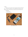
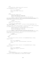
2.1 The Robots
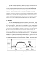
The most important mechanical units used in our project were the robots. When
the project was first proposed, we had the option of using one of two robot models made
by ActivMedia Robotics. The first choice was the AmigoBot, a smaller, but more mobile
robot. The second was the Pioneer AT, an all-terrain vehicle which had the capability to
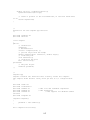
carry a large load. After weighing the capabilities of each robot we chose the Pioneer AT.
By using the Pioneer, we will have more leeway for future design expansion. The
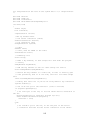
Pioneers drive capabilities were also important. It had the ability to rotate 360 degrees in
one place, making it easy to move around tight obstacles (Figure 2-2). Also, the Pioneer
is managed by an onboard microcontroller and mobile-robot server software. It is a fourwheel drive mobile robot that is truly intelligent, containing all of the basic components
for sensing and navigation in a real-world environment, including: battery power, drive
Figure 2-2 Pioneer's turning velocity profile
5
motors and wheels, position-speed encoders, integrated sensors, and accessories.1
The ActivMedia robot is the server in a client-server environment. It handles the
low-level details of mobile robotics, including: maintaining the platform’s drive speed,
heading over uneven terrain, and acquiring sensor readings from the sonar. The robots
require a client connection: software running on a computer workstation (laptop)
connected with the robot’s controller via a serial link that provides the high-level,
intelligent robot controls, including obstacle avoidance and path planning. The robot
performs these tasks through its onboard computing system, which consists of a
microcontroller (Figure 2-3; Figure 2-5), the heart of the robot, and the motor-driver
board (Figure 2-4; Figure 2-6), which controls all four motors to make sure they rotate
appropriately.
Figure 2-3 Old Pioneer Microcontroller
6
Figure 2-4 Old Pioneer Motor-Driver Board
Figure 2-5 New Pioneer Microcontroller
7
Figure 2-6 New Pioneer Motor-Drive Board
2.1.1 Software
The ActivMedia robots came with two basic software programs; ARIA and
Saphira. ARIA uses a C++ based development environment that provides a robust clientside interface to the robot’s controller and accessory systems. In fact, we manipulated the
ARIA software so that our robot system would interact with the other devices that we
attached (See Section 4.7 for more ARIA information). Saphira is a higher-level
environment that combines itself with ARIA to include a GUI simulator for robot
movement.
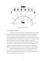
2.1.2 Sonar
The robot can support both front and rear sonar arrays, each with eight
transducers that provide object detection and range information for feature recognition, as
well as navigation around obstacles. We only chose to enable the robot’s front sonar
array, since using the rear sonar would cause interference with other robots in the
formation. The sonar positions in all arrays are fixed: one on each side of the robot, and
six situated in the front spaced at 20-degree intervals. Together, they provide 180 degrees
of seamless sensing for the platform. Sensitivity ranges from ten centimeters to nearly
five meters (Figure 2-7).
8
Figure 2-7 Front Sonar Array
2.1.3 Maintenance & Problems
To our surprise, the robots purchased from ActivMedia Robotics needed constant
maintenance and came with some major problems that affected the design and testing
process of our project. The first problem encountered occurred while performing
necessary maintenance on the first robot purchased. This robot had to have the software
system updated and the drive belts retightened. Unfortunately, we were unable to upload
the new system software onto the microcontroller, requiring us to send in the
microcontroller for a replacement. After replacing the microcontroller, this robot had no
further problems. Another problem that arose came from the configuration parameters
(Appendix: A) that had to be readjusted after each software update. Adjusting these
parameters was based on a trial and error process, which made it very time consuming.
The final robot malfunction occurred in two robots when their Motor Driver
circuit boards blew. This last malfunction caused havoc in the group since we were
unable to test our system while the robots where being serviced. Once all the robots were
fixed, we were able to perform tests as needed.
9
3. Instrumentation
3.1 Ultra Wideband
Ultra wide band (UWB) is a wireless communication device that uses a wide
spectrum of frequencies as apposed to a narrow band frequency. For example, a similar
wireless device called Bluetooth transmits only at a frequency of 2.4 GHz ± 1MHz.
UWB has the capability to transmit at extremely high rates. The current stage of the
technology allows a maximum transmit speed of about 500Mbps of raw data. Most other
wireless communication devices don’t even come close to the rate of transmission that
UWB does.
3.1.1 Pulse Modulation
To understand why UWB is significantly better in both previously stated
parameters, an examination of the modulation scheme must first be presented. Most
people are familiar with the common modulations schemes referred to as AM and FM.
These are the schemes allocated by the FCC specifically for radio transmissions. AM
uses amplitude modulation and FM uses frequency modulation. Both schemes are very
effective, but come with a specific frequency parameter. Both AM and FM require
signals to be transmitted at very specific
frequencies, called narrow band
frequencies.
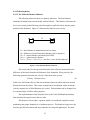
UWB uses a slightly different
modulation scheme, called Pulse
Figure 3-1 Pulse Modulation
Modulation (PM). Pulse modulation uses
short, low powered bursts of energy, on the order of picoseconds and milliwatts, to
transmit its signal (See Figure 3-1). These short bursts of energy are transmitted through
the antenna of the UWB unit and are received by another unit. The received bursts are
then decoded by taking into account the distance between bursts. For example, if a burst
is received a picosecond early then it is decoded as a binary 1; if it is received a
picosecond later than expected then it is decoded as a binary 0. This is a simplified
version of the complicated coding and decoding methods of a real UWB transmission.
10
3.1.2 Interference Issues
UWB is not a narrow band frequency device. That is, it does not transmit only at
specific frequencies. UWB still has a center frequency, but the band is normally spread
between two and four GHz. The units that were used in this project had a center
frequency of 4.7 and were spread over 3.2 GHz. This ultra wide range of transmit
frequencies gives some interesting characteristics to the system. The devices are no
longer susceptible to narrow band interference. This can best be illustrated by
comparison. When listening to the radio you may experience cross over from another
station that is close to the channel you are listening to. This happens because the transmit
frequencies are so close that they may in fact overlap sometimes. That interference is the
narrow band frequency interference. UWB does not have that problem because
information is sent over a range of frequencies instead of a single frequency. Even if
there is a high power spike at a single frequency within the transmit range of the UWB it
will only disturb an extremely small part of the overall signal
This works both ways. The signal is not only unsusceptible to narrow band
interference, but it does not interfere with narrow band frequencies either. These bursts
of energy that make up the transmission signal are very low powered. Due to the fact that
these bursts are spread over 3.2 GHz the signal comes out looking like Gaussian noise
(sometimes referred to as white noise). This type of noise is considered to be part of the
noise floor, or the noise commonly associated with a common, public environment.
3.1.3 Applications In The Project
Having a better understanding of what UWB is will give you a better idea of the
reasons it was used in this project. UWB had capabilities such as distance between units,
relative angle information between units, fast transmit speeds, and having no requirement
for line of sight. All of these capabilities were considered useful given the scope and
motivations of our project.
11
3.1.3.1 Relative Distance
The UWB units gave us the ability to determine the distance between units. This
was an essential part to maintaining the formation of the robots. The distance
information is obtained through the calculation of the time of flight between the antennas
of each unit. The time of flight, also referred to as time of arrival (TOA), is the time that
it takes for a signal to get to the receiving antenna and back. That time of flight is then
converted into a distance by mathematical equations.
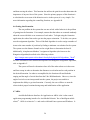
3.1.3.2 Angle Of Arrival
When the UWB units are
configured in the dual antenna
mode as pictured in Figure 3-2
they can give valuable angle
information. As pictured, a
relative angle between units is
found. Here the time of flight,
shown on figure as TOA (time of
arrival), is then converted into a
3-2 Dual Antenna Configuration
distance by taking into account
the travel speed of the energy burst and the distance between the dual antennas.
3.1.3.3 Additional Applications
Something very interesting can be done with the UWB units in a 3-D
environment. Using a third antenna we can also have the capability for a Cartesian “Z”,
or altitude, calculation. Having three antennas on each robot gives us the potential for
applications such as altitude mapping. The three antennas cover the x, y, and z planes of
3-D space. This means that a three-antenna configuration could give distance away,
relative angle difference, and relative altitude difference.
12
3.1.4 Advantages And Disadvantages
Some of the key advantages that UWB has over other wireless communication
devices include: no line of sight required, interference characteristics, relatively low
power, and high transmit rates. One of the main areas where this technology is inferior to
other communication devices is the distance a signal can travel. Project tests indicate that
the UWB units start to fail after about 100 feet apart. This can be slightly increased if the
acquisition header time is increased. Increasing the acquisition header essentially makes
the UWB units wait for a longer period of time before decoding the received data. It does
this to ensure that all the data that was sent has been received.
3.2 Digital Compass
Direction control was crucial to the mobility of the robots’ formation. Without
one, it would be near impossible for the robots to stay in the correct formation. We were
able devise two methods to control the robots’ direction; angle of arrival and an
electronic compass. The angle of arrival method would use a 2-antanna configuration to
compute the absolute direction and location of each robot. Ultimately, angle of arrival
would give the best data, but due to lack of technical support from the manufacturers, this
method was not implemented. Therefore, we chose an electronic compass, which would
calculate the absolute angle of the robot by using a 360-degree measurement. This
method was the quickest to implement, unfortunately the only drawback was that it did
not have the robust capabilities of angle of arrival.
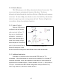
We used the CMPS01 electronic compass (Figure 3-3) as the solution to direction
control. This compass module has been specifically designed for use in robots as an aid
to navigation. The compass uses the Philips KMZ10A magnetic field sensor, which is
sensitive enough to detect the earth’s magnetic field. The module generates a number
that indicates the bearing of the robot in relation to the local magnetic field. The aim was
to produce a unique number to represent the direction the robot is facing. This number
can then be read by an OOPic microcontroller or a Stamp.
13
Figure 3-3 CMPS01 Electronic Compass
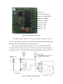
The compass module requires a 5 Volt power supply at a nominal 15 mAmp. It
receives its bearing data from PWM. The PWM signal is a pulse width modulated signal
with the positive width of the pulse representing the angle2.
The compass module requires a small processor to read the magnetic field data.
We used the BS2sx Stamp from Parallax to calculate data from the compass and pass it
through the serial port. The Stamp uses the BASIC programming language, where it can
Figure 3-4 Stamp & Compass Schematic
14
perform 10,000 instructions per second (50 Mhz clock), and can store 82K programs
(16K total), but only able to run one program at a time.
Implementing the Compass module with the Stamp was very easy considering
everything was documented on the Internet3.
3.3 Power Supplies
One criterion behind our project was to design the robots to be completely
autonomous. This means that all devices connected to the robots had to have their own
power supply to avoid the use of a cord. Overall, we had to design two types of battery
packs, one for the Ultra Wideband units, and another to power a hub, which was used to
connect the UWB to the laptops.
3.3.1 UWB
In the beginning stages of the project, the UWB power packs were crucial because
they gave us the ability to test the capabilities of the UWB. When designing the power
packs, we focused on simplicity and on battery life. It would need to put out a 7 Volt and
3 Amp for at least an hour, so we chose regular 7.2 Volt and 3 Amp/hrs RC car batteries.
These would make it
easier to recharge the
batteries. In the long run,
we were able power the
UWB units for about 1.5
hours (Figure 3-5).
Parts Included:
- 7.2 Volt RC
Battery
- 5 Amp Fuse
- Power Switch
Figure 3-5 UWB Power Pack
15
3.3.2 Hub
The hub power pack required a little more thought to design than the UWB power
packs. The same RC care batteries were used, in addition to plus we added a voltage
regulator at 5 Volts / 2 Amp to make sure we did not over power the hub (Figure 3-6).
Parts Included:
- 7.2 Volt RC Battery
- 5 Volt Voltage Regulator
Figure 3-6 Hub Power Pack
16
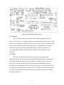
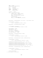
4. Control
The Control is the set of code that takes the desired action from the user and gives
the robot instructions which implement that action. It is essentially the translator between
the user and the robot hardware. The code consists of the program to access the user
database, the programs to determine the action to be taken by each robot, and the
interface that controls the robot and it various motors. This last interface is known as
ARIA and was provided by ActivMedia with the purchase of the robots. Figure 4-1
further illustrates the relationship between the Control and the rest of the Formation
system.
User
To GUI
Graphical User
Interface
Database
Formation Code
Control
ARIA
Robot
Robot Controller
To Robot
Figure 4-1 Overview of System Control
4.1 Programming Environment
The control code was written in C++ using the Microsoft Visual C++ Professional
Studio. It primarily consists of executable programs that use the Windows console and
have been successfully tested on Microsoft Windows 98 and Windows 2000.
17
4.2 Connecting to the User Interface
The control accesses the user input through the user database. The database is a
mySQL database consisting of a formation table and a destination table. For more
information on the database, refer section 5.1 in the Graphical User Interface portion of
this paper.
The control accesses the database with the help of mysql++, an open-source API
for MySQL and C++. It has different version that work with gnu or Microsoft Visual
C++. It comes with a user manual and a brief tutorial4. The code included in this project
is primarily based off the example entitled “custom3” in the tutorial. In general, it uses
typical SQL commands, but in a more complicated way.
Refer to Appendix B.1 for the actual database access code.
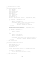
4.3 Behaviors
To implement the various algorithms of the system, we implemented a behavioral
approach. This approach treats all the different aspects of the system that are acting on
the formation, such as maintaining the formation and obstacle avoidance, as vector
forces. These aspects are things in the environment that would cause a change in the
formation’s position or velocity. For example, the destination of the robots acts as a
vector that pulls the formation towards it while obstacles in the formation’s path act as
vectors pushing the robots away. Figure 4-2 helps to illustrate the different vector forces
Obstacle
Obstacle
Goal
Goal
VGoal
VResultant
Robot
Robot
VObstacle
VObstacle
A
VGoal
B
Figure 4-2 Illustration of Behavior Vectors
18
acting on the system.
Side A of figure 4-2 shows the two vectors that are acting on the robot. VGoal is
the force pulling the robot towards its goal or destination. VObstacle is the force vector
pushing the robot away from the obstacle. Side B of the diagram illustrates the vector
sum of the two forces that creates VResultant. This vector is the force that now steers the
robot. As the robot moves away from the obstacle, the VObstacle will decrease so that VGoal
will become the predominant steering force in the system.
By using the vector approach, the system does not have to take into consideration
every possible obstacle or goal configuration. Instead, we create individual instructions
for each type of vector or behavior, and then by putting them all together, the system
achieves its goal in many different situations.
The behavioral approach also allows us to control the significance, or weight, of
one behavior over another. For example, if it was important that the robots maintain a
rigid formation, then we could set the weight factor for the formation behavior higher
than the weight of any other behavior. For example, in Figure 4-3, the standard resultant
vector is shown in side A, while in side B, the weight of the obstacle behavior has been
increased by a factor of two. This effectively changes the resultant vector so that the
robot moves much more dramatically than the standard resultant.
Obstacle
Obstacle
Goal
Goal
VResultant
Robot
VObstacle
Robot
VResultant
VGoal
VObstacle
VGoal
A
B
Figure 4-3 Behavioral Gain Factors
19
4.4 Implemented Behaviors
The control system divides the behaviors into two types. The first type determines
the action of the leading robot and the second type controls the following robot(s). The
lead robot could be simply any robot in the system chosen at random. In our current
implementation, the lead robot is whichever robot is running the leader application.
4.4.1 Lead Robot
4.4.1.1 The Go-To Behavior
The lead robot has two behaviors. The first is the Go-To behavior. This behavior
calculates the direct distance between the current location and the goal location, and the
action required to get the robot moving in that direction. This is illustrated in Figure 4-4
below. The diagram shows a formation of robots and their goal.
Robot
Robot
Distance (D)
Goal
Robot
D = Distance from current robot position to ending destination.
Ggoal = Gain factor for the velocity to the goal destination.
Vgoal = Ggoal *D (Vgoal = The force vector for the Go-To behavior)
Figure 4-4 The Go-To Behavior
This function gets the destination coordinates from the user database and directs
the robot to that location. The speed and direction vary depending on the current position
of the robot. The current implementation uses the following equation to calculate the
desired speed:
Velocity = √(D * 200 * 2)
mm/s
(1)
Where D is the distance from the current position to the goal. This equation is part of the
ARIA package. The velocity is calculated in millimeters per second.
20
The standard Go-To function was already implemented as part of the ARIA
system, however, some changes were required to adjust the function so that it complied
with the vector approach to a behavioral application.
The behavior is considered complete when the robot has reached its destination,
or is within 100 millimeters of the destination. This ‘close enough’ value can be changed
depending on how accurate the formation needs to be. However, for this project, the 100
millimeters value is good enough. Additionally, if the value is too small or zero, then the
robot may have trouble actually stopping at the exact desired location.
For more information on the implementation of the Go-To behavior, please to
Appendix B.3.
4.4.1.2 The Avoid Obstacles Behavior
The second behavior implemented on the lead robot is the behavior to avoid
obstacles. This behavior calculates the force vectors that push the robot away from
obstacles and the action required for the robot to avoid the obstacle. This behavior is
illustrated in Figure 4-5. Side A of the diagram illustrates the various forces acting on the
robot while side B illustrates the calculation of VObstacle by creating the vector sum of all
obstacle vectors.
Obstacle 1
V1
Obstacle 2
V2
V1
VObstacle
Robot
V2
A
B
Vn = velocity vector due to the Nth obstacle (xyz coordinates)
GObstacle = gain factor for obstacle avoidance
VObstacle = (V1+ V2+…+Vn) * GObstacle
(VObstacle = The force vector for the Obstacle Avoidance behavior)
Figure 4-5 The Obstacle Avoidance Behavior
21
This function gets the location of the nearest obstacle using the sonar range installed on
the robots. The speed and direction that the behavior directs the robot to move vary
depending on the size and proximity of the obstacles. The current uses the following
equation to calculate the new direction and desired speed of the robot:
Velocity = current speed – range of nearest obstacle
(2)
Angle = .5 * (current angle – angle of obstacle)
(3)
Again the velocity is counted in millimeters per second and the angle is calculated in
degrees counterclockwise from the x-axis.
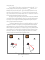
An extra adjustment to the implementation of this behavior checks to make sure
that the obstacle the sonar senses is not actually another robot in the formation. It checks
this by using the information about the formation, such as the coordinates of all the robots
in the system. Then, it calculates the degrees in the visual radius of the sonar that the
other robots are occupying. The behavior can then ignore any obstacles within the
specified range and angle of the other
robots. This is more clearly explained in
Robot
Figure 4-6. In this diagram, there is a
formation of two robots. The robot in
the rear is using the obstacle avoidance
function and must detect the forward
robot without misinterpreting the latter
Robot
as another obstacle. The lightly shaded
area indicates the range of the sonar, and
the darker shading represents the range
that the control system must ignore as
Figure 4-6 Adjustment of Obstacle Detection
for Other Robots
another robot.
The behavior does not have a point at which it is considered complete because
obstacle avoidance is a continuous process while the robot is in motion. For more
information on the implementation of the Obstacle Avoidance behavior, refer to
Appendix B.4.
22
4.4.2 Following Robot
4.4.2.1 The Maintain Distance Behavior
The following robots also have two primary behaviors. The first behavior
maintains the distance between the leader and the follower. This behavior calculates the
force vector acting on the following robot that pushes or pulls the robots into the proper
position in the formation. Figure 4-7 illustrates the behavior more clearly.
D
Robot
Robot
D = ideal distance to maintain between two robots
∆d = difference of actual from ideal distance (may be negative)
∆d = d – (actual distance calculated from UWB)
Gdistance = gain factor for distance
Vdistance = Gdistance * ∆d (Vdistance = the force vector for the behavior)
Figure 4-7 The Maintain Distance Behavior
The actual values for the speed and direction of the robot are determined by the
difference of the actual from the ideal distance of the formation. More precisely, the
following equations determine the velocity of the robot in the system:
Velocity = Distance Error
(4)
In this case, the Distance Error is the current distance between robots minus the desired
distance between the robots. This creates a simple linear acceleration with a maximum
velocity currently set at 500 millimeters per second. This maximum can be changed, but
it is currently kept at 500 for safety purposes.
The implementation of this function relies on the Ultra Wideband functionality
that calculates the range between the two units.
This behavior does not have a point at which it is considered complete because
maintaining the proper formation is a continuous process. This behavior begins once the
user has specified a formation and stops when the user stops the application. For more
23
information on the implementation of the behavior to maintain distance, refer to
Appendix B.6.
4.4.2.2 The Maintain Angle Behavior
The second behavior of the following robots is the behavior that maintains the
angles within the formation. The function is responsible for keeping the robot at a
specific angle relative to the leader. Essentially, this function ensures that the formation
is properly arranged beyond simply maintaining distances. This behavior relies on the
Ultra Wideband units to calculate the angle of arrival information. Figure 4-8 further
explains this behavior. The diagram shows one possible configuration of the robots in
the formation on side A. Side B illustrates the appropriate orientation for both robots in
the system. In this case, the robot needs to turn ∆θ to maintain the desired (ideal) angle
at the rotational velocity indicated by Vθ.
a
φ
a
Robot
θ
b
Robot
b
x
Robot
Robot
A
B
θ = ideal angle of arrival
φ = actual angle of arrival
∆θ = θ - φ = the difference between the ideal and the actual
φ = 90 – (cos-1 ((a2 + x2 – b2) / (2*a*x))
Vθ = ∆θ * Gθ (Vθ = The force vector for the behavior)
Figure 4-8 The Maintain Angle Behavior
This behavior relies on the angle of arrival information calculated with the dual
antenna configuration of the Ultra Wideband units. However, we were unable to utilize
the angle of arrival functionality due to versioning constraints. The manufacturer no
longer supports the version of the Ultra Wideband units used in the current system,
24
therefore it was not possible to utilize the dual antennas. Instead of using the angle of
arrival method, we used a compass to determine absolute angle. This value gives us the
direction that the robots are facing at any given moment. This primarily corrects the case
when the robots begin to veer off of the straight path and allows us to ensure that the
robots are all facing the same direction. The function calculates the angle to turn with the
following equation:
Angle = desired angle – current angle
(5)
For more information on the compass and maintain angle behavior implementation, refer
to Appendix B.7.
4.4.3 Behavior Extendibility
One goal of our system was to ensure system extendibility, or the behavior to use
any number of robots in a formation. One way this goal was achieved involves the
behaviors. It may appear difficult to add more robots to the system without extensive
adjustments to the function; however, no change is required. Adding more robots to the
system should not affect the behaviors because, by maintaining a set distance from the
leader and maintaining a relative angle (as illustrated in the sections 4.4.2.1 and 4.4.2.2)
from the leader, the robots should automatically maintain a set distance from all other
following robots. Essentially, by ensuring that each robot is oriented appropriately with
regards to the leading robot, then the entire formation will have the proper orientation.
Additionally, it is easy to add functionality to the system. The behaviors
themselves are easily modifiable. For example, the standard Go-To behavior goes
forward to a destination, but if you want to return to the original position, the robot turns
around 180 degrees and returns to the starting position. However, for the simple onedimensional testing, it was useful to have the robots simply travel back and forth without
turning around. A simple adjustment to the system was all that was required and then it
was possible to use this testing feature.
4.5 The Overall Control Function
In order to control the formation with the vectors from the behaviors, it was
necessary to create a controlling vector that is responsible for calculating the vector sum
25
and then moving the robots. This function also utilizes the gain factors that determine the
importance of any one facet of the system. Since the primary purpose of this function is
to calculate the vector sum of the behaviors active in the system, it is very simple. For
more information regarding the controlling function, see Appendix B.
4.6 Getting into Formation
The one problem in the system that was not solved with a behavior is the problem
of getting into the formation. For example, assume that the robots are scattered randomly
about the room with little or no awareness of each other. To begin using the formation
application, the robots first need to get into the proper orientation. To do this, our system
uses the assignment algorithm. This well-defined algorithm is used to assign a number of
items to the same number of positions by finding a minimum cost solution for the system.
The system uses the distance formula as the weight factor to determine the best fit.
Additionally, it implements Munkres’ Assignment Algorithm (also known as the
Hungarian Algorithm) described at the following website:
http://campus.murraystate.edu/academic/faculty/bob.pilgrim/445/algorithms_7.html5
For more information and a detailed description of the Hungarian Assignment Algorithm,
refer to Appendix C.
The system will need to determine where all of the other robots are in the room
and form a map in order to determine the distances to each other and to each position in
the desired formation. In order to accomplish this, the function will need both the
ranging and the angle of arrival data from the Ultra Wideband units. However, since the
angle of arrival was not incorporated into the system, the project was unable to
implement the ability to get into formation. Currently, the user will have to start the
robots in their proper locations during setup and initialization of the application.
4.7 ARIA
ActivMedia Robotics Interface for Application or ARIA is the “robot control
application-programming interface for ActivMedia Robotics’ line of intelligent mobile
robots”6. ARIA is written in C++ and works with both Linux systems and Windows. It
26
provides the functionality for connecting to the robot or the provided simulator, as well as
managing the various sensors that can be implemented on the robots.
ARIA provides functions for direct motion control, such as go forward 2 meters,
as well as functions for behavior based motion control. Behaviors in ARIA are known as
actions. The action system is priority based so the action with the highest behavior gets
to execute first. ARIA has several basic built-in actions, such as the Go-To function
mentioned above. However, it is easy to create new actions or modify old ones.
ARIA has a cycle time of 100 milliseconds. In one cycle, each action is executed
and the new values for speed and rotational angle are calculated. For more on ARIA and
actions, refer to the Aria Reference Manual which can be found at
http://robots.activmedia.com/ or look at Appendix B for action examples.
27
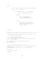
5. Graphical User Interface (GUI)
The main goal of the graphical user interface was to provide aesthetically pleasing
and easy to use software. Via the GUI a user would be able to control the robot
formation without physically touching the robots.
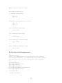
5.1 Software Tools and Components
To create the GUI, there were a few different technologies that could be used
effectively. The first thing taken into consideration was which programming language to
use. It was much easier to use C++ or a similar language to keep in sync with the ARIA
software, as opposed to using some other language. One possible option to accomplish
this was Microsoft Visual Studio’s Interdev which had graphical capabilities. We chose
to use a webpage structure for our GUI. This made the interface easier to construct and
access the database using SQL and Active Server Pages.
Each screen viewed by the user was constructed using the VBScript and HTML
languages. Dreamweaver was used to create buttons, hyperlinks, and help in debugging
the GUI. The database was created using MySQL database server and accessed via
Active Server Pages (ASP). All the laptops ran either Microsoft Windows 98 or 2000
and so given Windows’ server capabilities it was easy to set up one of the laptops as the
main unit. This laptop would be able to access the database, write to it, and transfer
commands to the formation code.
We chose to implement a database to store information about the formation
because it was a good way to maintain potentially large amounts of information which
could be easily accessed. MySQL7 is a program that allows you to quickly create a
database and can interface with Windows’ server capabilities. The Active Server Pages
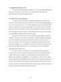
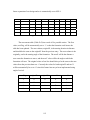
will send information to the database, which will later be retrieved by the formation code.
There are tables pertaining to formation as well as formation movement, each of which
currently contain rows to allow information for up to three robots. Depicted in Figure 5-1
is what a portion of the formations table would look like.
28
newFlag
numOfRobots
distance1
distance2
distance3
distance4
angle1
angle2
angle3
angle4
1
2
5
NULL
NULL
NULL
NULL
NULL
NULL
NULL
1
2
7
NULL
NULL
NULL
NULL
NULL
NULL
NULL
1
1
0
NULL
NULL
NULL
NULL
NULL
NULL
NULL
1
2
10
NULL
NULL
NULL
NULL
NULL
NULL
NULL
1
2
4
NULL
NULL
NULL
NULL
NULL
NULL
NULL
Figure 5-1 Excerpt from Formations Table
The first entry sets a flag value to ‘1’ every time a new row is entered into the
formation table so that the formation code will know when the table has been updated.
The next column displays the number of robots chosen to be in the formation, followed
by columns containing the distance to be maintained between robots, and the angle at
which each robot needs to be in relation to one another. The angle feature is meant for
future expansion of our design. There is also a table for formation movement which can
be viewed in the Database Appendix D as well as a list of SQL commands.
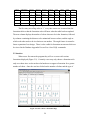
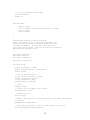
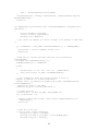
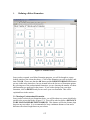
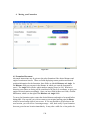
5.2 Interface
When a user first enters the program they will see a screen with various
formations displayed (Figure 5-2). Currently a user may only choose a formation with
only two robots since we do not have the hardware to support a formation for a greater
number of robots. Once the user has clicked on the number of robots and the type of
Figure 5-2 GUI: Choose a Formation Page
29
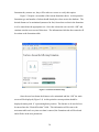
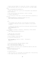
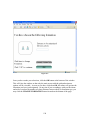
formation they want to use, they will be taken to a screen to verify their option.
Figure 5-3 depicts a screenshot of the current formation choice. At this point the
formation type and number of robots should already have been sent to the database. The
desired distance to be maintained (measured in feet) from robot to robot in the formation
is to be entered into the appropriate text. Once this is done the user can click “OK” and
continue onto the next screen of directions. The information which has been entered will
be written to the formations table.
Figure 5-3 GUI: Select Distance Page
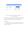
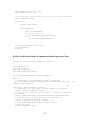
Once the user has chosen the distance to be maintained and hits “OK” the main
screen will be displayed (Figure 5-4) At this point the current position should be
displayed starting with ‘0’ representing home position. The distance to be traveled can
be entered into the “Desired Position” fields. This information will be sent to the
movement table and every time new data is entered, the formation code will be alerted
and will take in the new parameters.
30
Figure 5-4 GUI: Interactive Page
At any time the user can go back and change their current formation, or they can start and
stop the progress of the formation. The code for the various pages of GUI can be found
in Appendix E and a more detailed User Manual can be found in Appendix G.
5.3 Future Work
The Graphical User Interface currently functions independently of the formation
code. It has a limited sphere of control of the formation movement and still needs to be
implemented to a fuller degree.
31
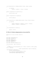
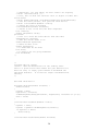
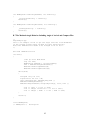
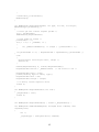
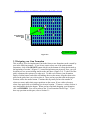
6. Integration and Test
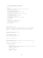
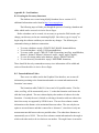
6.1 Long-Range Testing
An immediate concern in our project was finding out how far the UWB units
could be apart from each other and still pass information. A long-range test was
performed in the Leavey Center at Santa Clara University. The scope of this experiment
was to determine the maximum distance that the UWB units can be apart while still
passing correct information. Figure 6-1 shows the experiment set up. In this test there
was one stationary unit and one mobile unit. The mobile unit started at the same position
as the stationary one. It was then moved in increments of five feet to a distance of 170
feet. Figure 6-2 shows the results of that test. You will notice that as the units moved
further apart there were fewer readings. The receiver not being able to successfully get
the acquisition header and data can explain this phenomenon. After extending the
acquisition header these results were slightly improved.
UWB measured distance
(Ft)
Long Range Test
200
180
160
140
120
100
80
60
40
20
0
Series1
0
50
100
150
200
Actual Distance (Ft)
Figure 6-2 Long Range Results
Figure 6-1 Test Layout
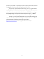
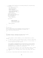
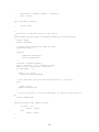
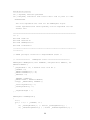
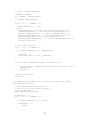
6.2 Formation Testing
The distance test was design to give us an idea of the transients associated with
system response. Two one-dimensional tests were performed. In both cases there was a
lead and a follow robot. The lead robot was programmed to move forward and
backward. The follow robot was programmed to follow the lead robot keeping a distance
of seven feet.
32
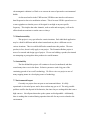
Figure 6-3 shows the first set of results. This is a graph of the percent of error in
the distance over a sample period. The curve shown here represents a response error.
That is, when the lead robot begins to
Response Error
16
move it takes the follow robot a certain
14
12
amount of response time to react to
Percent Error
10
8
changing distance. In essence, the lead
6
robot will have moved a little before the
4
2
33
31
29
27
25
23
21
19
17
15
13
9
11
7
5
3
1
0
-2
follow robot realizes that it needs to start
Samples
moving. Notice that after about 25
Figure 6-3 No Wall Test Results
samples the graph oscillates around zero
percent error. This happens when the follow robot reacts to the distance difference,
catches up, and is able to reach a more steady state of maintaining the distance from the
lead robot.
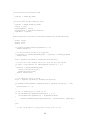
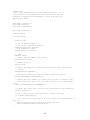
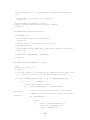
Response Error With Wall
As stated in section 3.1.4UWB is
25
able to go through most barriers and does
20
not require line of sight. To test this, a
Percent Error
15
10
thin metal wall was placed in between the
5
two UWB units. Figure 6-4 shows the
0
1 2 3
4 5 6 7
8 9 10 11 12 13 14 15 16 17 18 19 20 21 22 23 24 25 26 27 28
results of this thru wall test. When
-5
Samples
comparing the two test results, with wall
Figure 6-4 With Wall Test Results
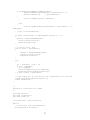
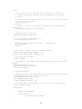
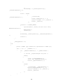
and without wall, we see that the response
error is slightly better without the wall (Figure 6-5). There is about a five percent
increase in response error when the thin wall is added. This is an expected result because
the equipment is not perfect.
25
20
15
Wi t hout Wal l
10
Wi t h Wal l
5
0
1
3
5
7
9
11
13
15
17
19
21
23
25
27
-5
Sa mpl e s
Figure 6-5 Wall vs. No Wall
33
7. Professional Issues
7.1 Social
Communities on Earth are continuously expanding, causing a greater need to
explore options outside of our planet; for example, Mars. With the capabilities of the
completely autonomous Formation Robots, we could explore and map the terrain of any
unknown area without the loss of human life. One major problem could arise from our
project. The problem follows the science fiction based theory, where giving more
intelligence to computerized devices could drastically change the outcome of human
kind.
7.2 Political
Our project had no intentions of having any political effect on the community.
On the other hand, there is only one potential impact that our group could see as being an
issue. In working with Lockheed Martin our Formation Robots design could be used for
future military combat. This potential for combat goes against past protests by Santa
Clara students and This the Santa Clara University Jesuit code.
7.3 Economic
Our project had very few economic hurdles to conquer. First off, most of our
equipment was purchased by the SCU Robotic Department or on loan from Lockheed
Martin (UWB). When economic considerations arose during the first stages of our
project, we received money from the Engineering Department for potential involvement
with the outside educational contributions.
7.4 Health and Safety
The only health issue related to our project may come in the form of
electromagnetic radiation from the wireless communication devices needed in our system
of robots. Ultra Wide Band is the only wireless communication device that may emit any
sort of electromagnetic radiation. Due to the fact that the signals sent and received by the
UWB units are low power, relative to analogous wireless communication devices, the
34
electromagnetic radiation is of little or no concern in terms of personal or environmental
health.
As discussed earlier in the UWB section, UWB does not interfere with narrow
band frequencies due to its modulation scheme. This is because UWB is spread over two
or more gigahertz so that the power of the signal is not high at any one specific
frequency. This implies that other channels, such as radio and emergency, will not be
affected and can continue to run the same as always.
7.5 Manufacturability
This project is very specialized to certain situations. Each individual application
may be a little bit different and the robots/control unit may have a different uses in
various situations. Thus it would be difficult to manufacture this product. The term
product, in fact, doesn’t really apply to our project. The Formation Robots project is
more of a research and design type of project. We are not building a product, but instead
are attempting to put together other products in a useful manner.
7.6 Sustainability
The idea behind this project will continue to be used, transformed, and then
reused many times over in the future. Robotic systems are such a big part of the
continuing growth of our world’s technology. We like to view our project as one of
many stepping stones in a developing corner of technology.
7.7 Environmental Impact
Currently our project does not pose an environmental threat. It is fully
operational via electrical power and so does not burn any gas or oil. The only possible
problem could be the disposal of the batteries, but since they are rechargeable that is not a
high concern. Not all parts that make up the system are biodegradable. Additionally,
there is nothing that is emitted during operation that calls for any worries related to the
environment.
35
7.8 Usability
In the system’s current state, it is fairly easy to use and a new user should be able
to learn the necessary functionality and maintenance of the formation by reading the
manual or being taught by someone who knows the technology. The basic knowledge
necessary to drive the formation should take about 5 or 10 minutes to learn. The actual
execution of the programs is straight forward with directions provided to the user on the
screen. If the system is already set up, the user does not need to know anything about the
robots or UWB provided they do not malfunction.
Potential problems for the user would most be problems connecting the UWB to
the computer and possibly initializing them, since this portion requires the most hardware
knowledge. The main disadvantage of the current system is that when receiving real time
commands from a user, they need to hold one of the laptops connected via serial port to a
robot. This is the most user unfriendly aspect, yet over all it is not much of an
inconvenience since the user may set up a program and watch the system run completely
autonomously.
Formation Robots is usable by anyone who wishes to command more than one
robot at a time by giving directional commands to one only robot. It does not take a lot
of study to learn the rudimentary basics necessary to drive of the formation as long as
someone knowledgeable with the system takes care of the maintenance. If the system
were on the market or used in research the appropriate technical support would be
provided.
7.9 Lifelong Learning
Lifelong learning requires that a person continue to expand his or her knowledge
by researching and learning new things. Throughout the process of this project, our
group practiced the skills that will help us learn new things in the future. For example,
we were required to research different algorithms and methods to control the formation
that are being studied in other research labs. Additionally, we had to learn new
technologies such as new programming languages, new software, and new hardware.
The process of learning new skills will be invaluable in our future careers.
36
Additionally, this project forced the members of our group to practice our
communication skills. We had to communicate ideas to each other, our advisors, and
others who were involved with the project. This is an important skill because in order to
continue learning new things, a person needs to able to understand new concepts and
communicate that new understanding to others. Therefore, this important teamwork skill
will be very beneficial in future learning experiences.
7.10 Compassion
Although it was not originally a goal or motivation for this project, the various
ways that the project results could be used to help others illustrate some degree of
compassion. For example, a formation of robots could be used to help explore a disaster
a rea that is unsafe for rescue workers. Clearly such motivation demonstrates a desire to
relieve the suffering of others.
37
8. Conclusion
8.1 Summary
Formation Robots has completed the goals in which were established at the
beginning of the project. We have a working prototype of a formation of two robots with
one dimensional movement capabilities. The formation is able to avoid obstacles to a
certain degree and can operate fully autonomously if desired. UWB units have been
successfully used to maintain a given distance from robot to robot.
Although a lot of groundwork has established over the duration of the year, there
is still much that can be done to improve the system. Angle of arrival can be
implemented using UWB so that the formation can have three-dimensional capabilities.
There are many areas in which the system can be improved upon. However, the necessary
foundations have been laid for future research and design.
8.2 Contributions
Formation Robots is the first senior design project at Santa Clara University that
has explored the possibilities of formation control. We were able to successfully control
two robots in a one-dimensional formation. Some of these algorithms could be the
building blocks for future senior design projects.
Without the help of industry it would have been rather difficult to gain all of the
necessary equipment. Through working with Lockheed Martin, in particular Bob
Dougherty, we helped to strengthen a University-Industry relationship. The goal was to
share our findings with Lockheed Martin in return for the usage of their UWB
technology. As a result of the mutual endeavor, UWB technology will continue to be
integrated into the Santa Clara University Robotics Program.
8.3 Future Extensions
This project has a lot of potential for expansion. Logically, the next step for this
project is to implement the next generation of Ultra Wideband technology. The new
technology will have the capability to transmit the angle of arrival data that would allow
for two-dimensional control of the formation, as well as more complex formations. Once
the ability for two-dimensional control has been implemented, it will be possible to
38
experiment with three or more robots in formation. After this point, it would be useful to
test the behavioral controls by adjusting the various gain factors and then to compare the
behavioral algorithm to other control possibilities. Beyond this point, future expansion
may include application specific development and testing as well as testing technologies
other than Ultra Wideband.
8.4 Lessons Learned
Over the course of the year we have not only learned to apply our cumulative
knowledge to building a control system, but we have also gotten a glimpse into issues of
the real world. Once a project’s scope is bigger than something one person can
accomplish, it becomes necessary to some times rely on the support of others. While
technical as well as mental support is helpful, there are times where it may not come in
time and a backup plan is necessary. We also found that prototypes could be very useful
and may have helped to find problems earlier on.
Possibly one of the most important aspects of group design that many people tend to
overlook is group dynamics. When everyone in the team gets along and there is a relaxed
friendly atmosphere it is much easier to get work done and keep everyone happy. Work
no longer becomes a chore but something to be looked forward to, and at its worst
tolerated since the company is always good. We found the keys to a successful senior
design project to be an interesting and motivating project, support from our advisors
above and beyond their duties, and unique group dynamics.
39
Appendix A - Compass Code
BASIC Code
'**
I2C
Routines for the Basic
Stamp
'**
using the
CMPS01/CMPS03 CompassModule
'**
'**
'**
This Code has been Tested on BS2 and
BS2p
'** It should work equally well on the BS2e and
BS2sx
'**
'***********************************************************
SDA con
8
SCL con
9
SDAin var in8
SDAout var
out8
DAdir var
dir8
' I2C data
' I2C clock
loop var
I2cBuf var
I2cAddr var
I2cReg var
I2cData var
I2cAck var
'
'
'
'
'
'
byte
byte
byte
byte
word
bit
**
**
**
**
**
**
' To change the pins used, alter these 5 lines
' The 4 SDA numbers must be the same, of course
just a looping counter
I2c read/write buffer
Address of I2C device
Register number within I2C device
Data to read/write
Acknowledge bit
Main:
I2cAddr =
$c0
' CMPS01/03 Compass module address
I2cReg =
1
' Bearing as 0-255 (BRAD)
gosub I2cByteRead
debug 2,0,0, "Compass Bearing (0-255 BRAD) ", dec3 I2cData
I2cReg =
2
' Bearing as 0-359.9 degrees
gosub I2cWordRead
debug 2,0,1, "Compass Bearing (0-359 Degrees ", dec3 I2cData/10
goto main
'------------------------------------------------------------------------------------------' I2C subroutines follow
'------------------------------------------------------------------------------------------I2cByteWrite:
' writes I2cData.lowbyte to I2cReg at I2cAddr
gosub I2cStart
I2cBuf = I2cAddr
gosub
I2cOutByte ' send device address
I2cBuf = I2cReg
gosub
I2cOutByte ' send register number
I2cBuf = I2cData.lowbyte
gosub
I2cOutByte
' send the data
gosub I2cStop
return
I2cWordWrite:
gosub I2cStart
' writes I2cData to I2cReg at I2cAddr
40
I2cBuf = I2cAddr
gosub
I2cOutByte
' send device address
I2cBuf = I2cReg
gosub
I2cOutByte
' send register number
I2cBuf = I2cData.highbyte
gosub
I2cOutByte
' send the data - high byte
I2cBuf = I2cData.lowbyte
gosub
I2cOutByte
' send the data - low byte
gosub I2cStop
return
I2CByteRead:
gosub I2cStart
I2cBuf = I2cAddr
gosub
I2cOutByte
I2cBuf = I2cReg
gosub
I2cOutByte
gosub
I2cStart
I2cBuf = I2cAddr | 1
gosub
I2cOutByte
I2cAck =
0
gosub I2cInByte
I2cData.lowbyte = I2cBuf
I2cData.highbyte = 0
gosub I2cStop
return
I2CWordRead:
gosub I2cStart
I2cBuf = I2cAddr
gosub
I2cOutByte
I2cBuf = I2cReg
gosub
I2cOutByte
gosub
I2cStart
I2cBuf = I2cAddr | 1
I2cAck =
1
gosub
I2cOutByte
gosub I2cInByte
I2cData.highbyte =I2cBuf
I2cAck =
0
gosub I2cInByte
I2cData.lowbyte = I2cBuf
gosub I2cStop
return
' send device address
' send register number
' repeated start
' send device address (with read set)
' send Nak
' read the data
' send device address
' send register number
' repeated start
' send Ack
' send device address (with read set)
' read the data
' send Nak
I2cOutByte:
shiftout SDA, SCL, MSBFIRST, [I2cBuf]
input SDA
high
SCL
' clock in the ack' bit
low SCL
return
I2cInByte:
shiftin SDA, SCL, MSBPRE, [I2cBuf]
SDAout = 0
SDAdir = I2cAck
high
SCL
' clock out the ack' bit
low SCL
input SDA
return
41
I2cStart
high SDA
high SCL
low SDA
low SCL
return
' I2C start bit sequence
I2cStop:
low SDA
high SCL
high SDA
return
' I2C stop bit sequence
42
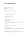
Appendix B - Control Code
B.1 Database Access Code
/*
custom3.h
Definition for custom3
*/
#include
#include
#include
#include
#include
<iostream>
<vector>
<sqlplus.hh>
<custom.hh>
"util.hh"
#include "formationClass.h"
int getNewest();
formationClass getFormation(int row);
/*
Custom3.cpp
This file, based on the mysql++ tutorial provides the
primary interface between the C++ code and the user
database, it grabs the database information and creates
a formation out of it.
*/
#include "custom3.h"
sql_create_11 (formations,
// struct name,
1,11,
int, count,
int, newFlag,
// type, id
int, numOfRobots,
double, distance1,
double, distance2,
double, distance3,
double, distance4,
double, angle1,
double, angle2,
double, angle3,
double, angle4)
// Create the formation of robots
formation getFormation(int row)
{
cchar* myDB = "FormationRobots";
Connection con(myDB);
Query query = con.query();
query << "select * from formations where count = '" << row "'";
vector < stock > res;
query.storein (res);
43
formations row = res[0];
// This method needs to be improved to allow for
// more than 2 robots
coordinate positions[numOfRobots + 1];
coordinate myCoordinate();
positions[0] = myCoordinate;
positions[1] = coordinate(distance1, distance2);
positions[2] = coordinate(distance2, distance3);
positions[3] = coordinate(distance3, distance4);
formation myFormation(row.numOfRobots, positions);
return myFormation;
}
// Get the newest formation information
int getNewest()
{
try { // its in one big try block
int newestRow = 0;
cchar* myDB = "FormationRobots";
Connection con(myDB);
Query query = con.query();
query << "select * from formations where newFlag = '1'";
Result res = query.store();
if (res.empty())
throw BadQuery("Nothing New");
// here we are testing if the query was successful, if not throw a
bad query
int size = res.size();
for(int i = 0; i < size; i++)
{
formations row = res[i];
if(row.newFlag == 1)
{
newestRow = row.count;
formations row2 = row;
// Now we need to create a copy so that the replace
query knows
// what the original values are.
row.newFlag = 0; // now change item
query.update(row2, row);
// form the query to replace the row
// the table name is the name of the struct by
default
cout << "Query : " << query.preview() << endl;
44
// show the query about to be executed
query.execute();
// execute a query that does not return a result set
} // end if
} // end for loop
return newestRow;
} catch (BadQuery er) {
cerr << "Error " << endl;
return -1;
} catch (BadConversion er) {
return -1;
}
}
/*
SimpleFollow.cpp
This is the implementation of the following robot behavior
for maintain distances. It contains the main() that controls
the following robot. It also sets up the robot interface.
It is almost the same as the SimpleFollow provided in the
following robot section, but with changes to allow input to
come from the database rather than the user.
*/
#include
#include
#include
#include
#include
#include
#include
"Aria.h"
"PADRequest.h"
<stdio.h>
<iostream.h>
"ActionMaintainDistance.h"
"PADFunctions.h"
"custom3.h"
int main(void)
{
double goalRange;
int inFront = 0;
bool frontFlag = false;
bool simulator;
formationClass myFormation();
// Get the formation information
int row = getNewest();
if(row > 0)
{
myFormation = getFormation(row);
}
coordinate myCoordinate = myFormation.getPosition(2);
goalRange = myCoordinate.getX();
//Set up Ultra Wide Band
long int rate;
45
PADRequest* PADComm = initializePAD();
rate = PADComm->RequestRateGet();
PADComm->VerbosityReadSet(0);
PADComm->VerbosityWriteSet(0);
//Set up Pioneer Robot
// the serial connection (robot)
ArSerialConnection serConn;
// tcp connection (sim)
ArTcpConnection tcpConn;
// robot
ArRobot robot;
// sonar, must be added to the robot
ArSonarDevice sonar;
// mandatory init
Aria::init();
// Make a key handler, so that escape will shut down the program
// cleanly
ArKeyHandler keyHandler;
// Add the key handler to Aria so other things can find it
Aria::setKeyHandler(&keyHandler);
// Attach the key handler to a robot now, so that it actually gets
// some processing time so it can work, this will also make escape
exit
robot.attachKeyHandler(&keyHandler);
// modify this next line if you're not using default tcp connection
tcpConn.setPort();
// see if we can get to the simulator (true is success)
if (tcpConn.openSimple())
{
// we could get to the sim, so set the robots device connection to
the sim
printf("Connecting to simulator through tcp.\n");
robot.setDeviceConnection(&tcpConn);
simulator = true;
}
else
{
// we couldn't get to the sim, so set the port on the serial
// connection and then set the serial connection as the robots
// device
// modify the next line if you're not using the first serial port
// to talk to your robot
serConn.setPort();
printf(
"Could not connect to simulator, connecting to robot through
serial.\n");
robot.setDeviceConnection(&serConn);
46
simulator = false;
}
// add the sonar to the robot
robot.addRangeDevice(&sonar);
// try to connect, if we fail exit
if (!robot.blockingConnect())
{
printf("Could not connect to robot... exiting\n");
Aria::shutdown();
return 1;
}
// turn on the motors, turn off amigobot sounds
robot.comInt(ArCommands::ENABLE, 1);
robot.comInt(ArCommands::SOUNDTOG, 0);
// Get the user defined parameters for the system
cout << "Current range is: " << getRange (PADComm, simulator, 0, 0,
false) << endl;
// If the robot is in front, then to move closer to the other robot
// then this robot needs to move backward rather than forward
if(inFront == 1)
frontFlag = true;
// the behaviors from above, and a stallRecover behavior that uses
defaults
ArActionAvoidFront avoid;
ArActionStallRecover recover;
ActionMaintainDistance maintainDistance(goalRange, PADComm,
frontFlag, simulator);
// add our actions in a good order, the integer here is the priority,
// with higher priority actions going first
robot.addAction(&recover, 100);
robot.addAction(&maintainDistance, 50);
//robot.addAction(&avoid, 45);
// run the robot, the true here is to exit if it loses connection
robot.run(true);
// now just shutdown and go away
Aria::shutdown();
return 0;
}
B.2 Lead Robot Implementation
/*
SimpleAvoid.cpp
This is the actual implementation that is currently used
47
on the leading robots. It includes the primary main() of
the system. It also sets up the robot to receive commands
*/
#include
#include
#include
#include
"Aria.h"
<stdio.h>
<iostream.h>
"ActionGo.h"
int main(void)
{
double
double
double
ArPose
ArPose
goalX;
goalY;
goalTh;
goalPosition;
currentPosition;
const double avoidWeight = 1.0;
const double goToWeight = 1.0;
//Set up Pioneer Robot
// the serial connection (robot)
ArSerialConnection serConn;
// tcp connection (sim)
ArTcpConnection tcpConn;
// robot
ArRobot robot;
// sonar, must be added to the robot
ArSonarDevice sonar;
// mandatory init
Aria::init();
// modify this next line if you're not using default tcp connection
tcpConn.setPort();
// see if we can get to the simulator (true is success)
if (tcpConn.openSimple())
{
// we could get to the sim, so set the robots device connection to
the sim
printf("Connecting to simulator through tcp.\n");
robot.setDeviceConnection(&tcpConn);
}
else
{
// we couldn't get to the sim, so set the port on the serial
// connection and then set the serial connection as the robots
// device
// modify the next line if you're not using the first serial port
// to talk to your robot
serConn.setPort();
printf(
48
"Could not connect to simulator, connecting to robot through
serial.\n");
robot.setDeviceConnection(&serConn);
}
// add the sonar to the robot
robot.addRangeDevice(&sonar);
// try to connect, if we fail exit
if (!robot.blockingConnect())
{
printf("Could not connect to robot... exiting\n");
Aria::shutdown();
return 1;
}
// turn on the motors, turn off amigobot sounds
robot.comInt(ArCommands::ENABLE, 1);
robot.comInt(ArCommands::SOUNDTOG, 0);
coordinate coord1 = coordinate(0,0);
coordinate coord2 = coordinate(0,500);
coordinate myPositions[2] = {coord1, coord2};
currentPosition = robot.getPose();
cout << "Current X: " << currentPosition.getX() << endl;
cout << "Current Y: " << currentPosition.getY() << endl;
cout << "Enter the desired x coordinate:" << endl;
cin >> goalX;
cout << "Enter the desired y coordinate:" << endl;
cin >> goalY;
goalTh = 0;
goalPosition.setPose(goalX, goalY, goalTh);
// the behaviors from above, and a stallRecover behavior that uses
defaults
completeVector control;
ActionAvoidObstacle avoid(myPositions, 2, avoidWeight, 2, &control);
ArActionStallRecover recover;
ActionGo go(goalPosition, 100, 500, goToWeight, 150, 7, &control);
// add our actions in a good order, the integer here is the priority,
// with higher priority actions going first
robot.addAction(&recover, 100);
robot.addAction(&go, 30);
robot.addAction(&avoid, 30);
robot.addAction(&control, 90);
// run the robot, the true here is to exit if it loses connection
robot.runAsync(false);
while(true)
{
while(!go.haveAchievedGoal())
49
{
currentPosition = robot.getPose();
cout << "Current X: " << currentPosition.getX() << endl;
cout << "Current Y: " << currentPosition.getY() << endl;
ArUtil::sleep(1000);
}
avoid.goalDone();
cout << "Acheived Goal!" << endl;
cout << "Enter the desired x coordinate:" << endl;
cin >> goalX;
cout << "Enter the desired y coordinate:" << endl;
cin >> goalY;
goalPosition.setPose(goalX, goalY, goalTh);
go.setGoal(goalPosition);
avoid.newGoal();
control.restart();
}
// now just shutdown and go away
Aria::shutdown();
return 0;
}
/*
Definition for the completeVector class
*/
#include
#include
#include
#include
"Aria.h"
"BuildObstacleMap.h"
<stdio.h>
<iostream.h>
class completeVector: public ArAction
{
public:
// constructor, sets myDistance, robot, and the PAD
completeVector(void);
// destructor, its just empty, we don't need to do anything
virtual ~completeVector(void) {};
// set the robot
void setRobot(ArRobot *robot);
// fire, this is what the resolver calls to figure out what this
action wants
virtual ArActionDesired *fire(ArActionDesired currentDesired);
// get velocity
double getVelocity();
// get angle
double getAngle();
// add to the velocity
void addVelocity(double velocity, double weight);
// add to the angle
void addAngle(double angle, double weight);
50
// set the velocity, primarily used for stopping
void setVelocity(double velocity);
// subtract a velocity
void subVeocity(double velocity, double weight);
// subtract from the angle
void subAngle(double angle, double weight);
// add to the angle with a delta
void addDeltaAngle(double angle, double weight);
// reset the stop variable
void restart();
protected:
// what the action wants to do
ArActionDesired myDesired;
// the velocity
double myVelocity;
// the angle
double myAngle;
// stop variable
bool myStop;
};
/*
completeVector.cpp
The complete vector is the controlling program in the system.
It controls the movements of the robot by creating the vector
sum of all of the behaviors in the system.
*/
#include "completeVector.h"
#include <ariaUtil.h>
const double myMaxSpeed = 500;
/*
This is the constructor
*/
completeVector::completeVector() :
ArAction("Obstacle")
{
myAngle = 0;
myVelocity = 0;
myStop = false;
setNextArgument(ArArg("Angle", &myAngle, "The angle the bot should
face."));
setNextArgument(ArArg("Velocity", &myVelocity, "The desired
velocity of the robot"));
}
/*
Sets the myRobot pointer (all setRobot overloaded functions must do
this),
finds the sonar device from the robot, and if the sonar isn't there,
then it deactivates itself.
*/
void completeVector::setRobot(ArRobot *robot)
51
{
myRobot = robot;
}
/*
This fire is the whole point of the action.
*/
ArActionDesired *completeVector::fire(ArActionDesired currentDesired)
{
// reset the actionDesired (must be done)
myDesired.reset();
myDesired.setDeltaHeading(myAngle);
// now set the velocity
myDesired.setVel(myVelocity);
// return a pointer to the actionDesired, so resolver knows what
to do
return &myDesired;
}
void completeVector::addVelocity(double velocity, double weight)
{
if(!myStop)
{
myVelocity = (velocity * weight) + myVelocity;
if(velocity > myMaxSpeed)
myVelocity = myMaxSpeed;
}
}
void completeVector::addAngle(double angle, double weight)
{
if(!myStop)
myAngle = (angle * weight) + myAngle;
}
void completeVector::setVelocity(double velocity)
{
if(!myStop)
{
myVelocity = velocity;
if(velocity == 0)
myStop = true;
}
}
void completeVector::subVeocity(double velocity, double weight)
{
if(!myStop)
{
myVelocity = myVelocity - (velocity * weight);
if(myVelocity < -myMaxSpeed)
myVelocity = -myMaxSpeed;
}
}
52
void completeVector::subAngle(double angle, double weight)
{
if(!myStop)
myAngle = myAngle - (angle * weight);
}
double completeVector::getVelocity()
{
return myVelocity;
}
double completeVector::getAngle()
{
return myAngle;
}
void completeVector::addDeltaAngle(double angle, double weight)
{
if(!myStop)
{
double difference = myAngle - (angle * weight);
myAngle = myAngle + difference;
}
}
void completeVector::restart()
{
myStop = false;
}
B.3 The Go-To Behavior Implementation and Associated Files
/*
Definition for the ActionGo function
*/
#include
#include
#include
#include
#include
#include
#include
"ariaTypedefs.h"
"ariaUtil.h"
"ArAction.h"
"ArExport.h"
"ariaOSDef.h"
"ArRobot.h"
"ActionAvoidObstacle.h"
class ActionGo : public ArAction
{
public:
ActionGo::ActionGo(ArPose goal, double closeDist, double speed,
double myWeight,
double speedToTurnAt, double turnAmount,
completeVector* myControl);
virtual ~ActionGo(void);
bool ActionGo::haveAchievedGoal(void);
void ActionGo::cancelGoal(void);
void ActionGo::setGoal(ArPose goal);
53
virtual ArActionDesired *fire(ArActionDesired currentDesired);
protected:
int myDirectionToTurn;
bool myPrinting;
double myCloseDist;
double mySpeed;
double mySpeedToTurnAt;
double myTurnAmount;
completeVector* control;
ArPose myGoal;
double myCurTurnDir;
ArActionDesired myDesired;
bool myTurnedBack;
ArPose myOldGoal;
double myWeight;
enum State
{
STATE_NO_GOAL,
STATE_ACHIEVED_GOAL,
STATE_GOING_TO_GOAL
};
State myState;
};
/*
ActionGo.cpp
This is the function that implements the Go-To behavior.
It is primarily taken from ActivMedia's example, but
with a few minor modifications
*/
/*
ActivMedia Robotics Interface for Applications (ARIA)
Copyright (C) 2002, ActivMedia Robotics, LLC
This program is free software; you can redistribute it and/or
modify
it under the terms of the GNU General Public License as published
by
the Free Software Foundation; either version 2 of the License, or
(at your option) any later version.
This program is distributed in the hope that it will be useful,
but WITHOUT ANY WARRANTY; without even the implied warranty of
MERCHANTABILITY or FITNESS FOR A PARTICULAR PURPOSE. See the
GNU General Public License for more details.
You should have received a copy of the GNU General Public License
along with this program; if not, write to the Free Software
Foundation, Inc., 59 Temple Place, Suite 330, Boston, MA 021111307 USA
If you wish to redistribute ARIA under different terms, contact
54
ActivMedia Robotics for information about a commercial version of ARIA
at
[email protected] or
ActivMedia Robotics, 44 Concord Street, Peterborough, NH 03458; 603924-9100
*/
#include "ariaOSDef.h"
#include "ActionGo.h"
#include "ArRobot.h"
ActionGo::ActionGo(ArPose goal, double closeDist, double speed, double
weight,
double speedToTurnAt, double turnAmount,
completeVector* myControl):
ArAction("Go")
{
myDirectionToTurn = 1;
myPrinting = false;
myWeight = weight;
//setNextArgument(ArArg("goal", &myGoal, "ArPose to go to.
(ArPose)"));
setGoal(goal);
setNextArgument(ArArg("close dist", &myCloseDist,
"Distance that is close enough to goal. (mm)"));
myCloseDist = closeDist;
setNextArgument(ArArg("speed", &mySpeed,
"Speed to travel to goal at. (mm/sec)"));
mySpeed = speed;
setNextArgument(ArArg("speed to turn at", &mySpeedToTurnAt,
"Speed to start obstacle avoiding at (mm/sec)"));
mySpeedToTurnAt = speedToTurnAt;
setNextArgument(ArArg("amount to turn", &myTurnAmount,
"Amount to turn when avoiding (deg)"));
myTurnAmount = turnAmount;
// Had to add the completeVector to allow us to use our
// controlling function
control = myControl;
}
ActionGo::~ActionGo(void)
{}
bool ActionGo::haveAchievedGoal(void)
{
if (myState == STATE_ACHIEVED_GOAL)
return true;
else
return false;
}
55
void ActionGo::cancelGoal(void)
{
myState = STATE_NO_GOAL;
}
void ActionGo::setGoal(ArPose goal)
{
myState = STATE_GOING_TO_GOAL;
myGoal = goal;
myTurnedBack = false;
myCurTurnDir = myDirectionToTurn;
myOldGoal = myGoal;
}
ArActionDesired *ActionGo::fire(ArActionDesired currentDesired)
{
double angle;
double dist;
double vel;
if (myGoal.findDistanceTo(myOldGoal) > 5)
setGoal(myGoal);
// if we're there we don't do anything
if (myState == STATE_ACHIEVED_GOAL || myState == STATE_NO_GOAL)
return NULL;
dist = myRobot->getPose().findDistanceTo(myGoal);
// if we are close enough and slow, stop moving and return
if (dist < myCloseDist && fabs(myRobot->getVel() < 5))
{
myState = STATE_ACHIEVED_GOAL;
control->setVelocity(0);
myDesired.setVel(0);
return &myDesired;
}
// see where we want to point
angle = myRobot->getPose().findAngleTo(myGoal);
if (ArMath::fabs(ArMath::subAngle(angle, myRobot->getTh())) > 120)
{
myCurTurnDir *= -1;
}
// see if somethings in front of us
if (currentDesired.getMaxVelStrength() > 0 &&
currentDesired.getMaxVel() < mySpeedToTurnAt)
{
control->addDeltaAngle(myTurnAmount * myCurTurnDir, myWeight);
}
else
{
// see if we want to just point at the goal or not
56
if (ArMath::fabs(ArMath::subAngle(angle,
ArMath::addAngle(myTurnAmount * myCurTurnDir * -1,
myRobot->getTh())))
> myTurnAmount/2)
{
control->addAngle(angle, myWeight);
}
else
{
control->addDeltaAngle(myTurnAmount * myCurTurnDir * -1,
myWeight);
}
} // end if currentDesired ...
if (dist < myCloseDist && fabs(myRobot->getVel() < 5))
{
myState = STATE_ACHIEVED_GOAL;
control->setVelocity(0);
myDesired.setVel(0);
}
// if we're close, stop
else if (dist < myCloseDist)
{
myState = STATE_ACHIEVED_GOAL;
control->setVelocity(0);
myDesired.setVel(0);
}
else
{
vel = sqrt(dist * 200 * 2);
if (vel > mySpeed)
vel = mySpeed;
control->addVelocity(vel, myWeight);
myDesired.setVel(myRobot->getVel());
} // end if dist < myCloseDist
// keep status quo for now and let the completeVector do the work
//myDesired.setVel(myRobot->getVel());
return &myDesired;
}
/*
Definition of ActionGo for lead1d
*/
#include "Aria.h"
#include <iostream.h>
#include <stdio.h>
class ActionGo : public ArAction
{
public:
// constructor sets myStopDistance
ActionGo(double Distance);
57
// destructor, its just empty, we don't need to do anything
virtual ~ActionGo(void) {};
// fire, this is what the resolver calls to figure out what this
action wants
virtual ArActionDesired *fire(ArActionDesired currentDesired);
// sets the robot pointer, also gets the sonar device
virtual void setRobot(ArRobot *robot);
// change the value of distance
void setDistance(double distance);
// checks to see if the move has been completed
bool isDone();
double abs(double value);
protected:
// this is to hold the sonar device form the robot
ArRangeDevice *mySonar;
// what the action wants to do
ArActionDesired myDesired;
// where we want to be
double myDistance;
// to know when we are done
bool done;
// to know if we are going backwards
bool backwards;
};
/*
actionGo.cpp for lead1d
lead1d = lead one-dimensional for the leading robot.
This is a quick action that models the goTo behavior but
does not turn, it simply goes forward or backwards the
specified distance. It allows for simple one-dimensional
Testing.
*/
#include "ActionGo.h"
ActionGo::ActionGo(double Distance) :
ArAction("Go")
{
mySonar = NULL;
myDistance = Distance;
setNextArgument(ArArg("distance", &myDistance, "Distance to go."));
done = false;
}
void ActionGo::setRobot(ArRobot *robot)
{
myRobot = robot;
mySonar = myRobot->findRangeDevice("sonar");
if (mySonar == NULL)
deactivate();
}
void ActionGo::setDistance(double distance)
58
{
myDistance = myRobot->getX() + distance;
done = false;
}
bool ActionGo::isDone()
{
return done;
}
/*
This fire is the whole point of the action.
*/
ArActionDesired *ActionGo::fire(ArActionDesired currentDesired)
{
double speed;
double currentX;
// reset the actionDesired (must be done)
myDesired.reset();
if(done)
{
myDesired.setVel(0);
return &myDesired;
}
currentX = myRobot->getX();
cout << "Current: " << currentX << endl;
double diff = myDistance - currentX;
if (abs(diff) > 1)
{
speed = .8 * diff;
myDesired.setVel(speed);
}
// the range was less than the stop distance, so just stop
else
{
done = true;
myDesired.setVel(0);
}
// return a pointer to the actionDesired, so resolver knows what to
do
return &myDesired;
}
double ActionGo::abs (double value)
{
if(value < 0)
return -value;
else
return value;
}
/*
59
lead1d.cpp
This is the implementation of the lead1d function. It is
very similar to the simpleAvoid functionality but without
obstacle avoidance and implemented to work with the onedimensional tests.
*/
#include <ariaUtil.h>
#include <stdio.h>
#include <iostream.h>
#include "actionGo.h"
double askX();
int main(void)
{
double goalX;
/* Set up Pioneer Robot */
// the serial connection (robot)
ArSerialConnection serConn;
// tcp connection (sim)
ArTcpConnection tcpConn;
// robot
ArRobot robot;
// sonar, must be added to the robot
ArSonarDevice sonar;
// mandatory init
Aria::init();
// Make a key handler, so that escape will shut down the program
// cleanly
ArKeyHandler keyHandler;
// Add the key handler to Aria so other things can find it
Aria::setKeyHandler(&keyHandler);
// Attach the key handler to a robot now, so that it actually gets
// some processing time so it can work, this will also make escape
exit
robot.attachKeyHandler(&keyHandler);
// modify this next line if you're not using default tcp connection
tcpConn.setPort();
// see if we can get to the simulator (true is success)
if (tcpConn.openSimple())
{
// we could get to the sim, so set the robots device connection to
the sim
printf("Connecting to simulator through tcp.\n");
robot.setDeviceConnection(&tcpConn);
}
60
else
{
// we couldn't get to the sim, so set the port on the serial
// connection and then set the serial connection as the robots
// device
// modify the next line if you're not using the first serial port
// to talk to your robot
serConn.setPort();
printf(
"Could not connect to simulator, connecting to robot through
serial.\n");
robot.setDeviceConnection(&serConn);
}
// add the sonar to the robot
robot.addRangeDevice(&sonar);
// try to connect, if we fail exit
if (!robot.blockingConnect())
{
printf("Could not connect to robot... exiting\n");
Aria::shutdown();
return 1;
}
// turn on the motors, turn off amigobot sounds
robot.comInt(ArCommands::ENABLE, 1);
robot.comInt(ArCommands::SOUNDTOG, 0);
// ask the user for input
goalX = askX();
// the behaviors from above, and a stallRecover behavior that uses
defaults
ArActionAvoidFront avoid;
ArActionStallRecover recover;
ActionGo go(goalX);
go.setRobot(&robot);
// add our actions in a good order, the integer here is the priority,
// with higher priority actions going first
robot.addAction(&recover, 100);
robot.addAction(&go, 60);
//robot.addAction(&avoid, 55);
// run the robot, the true here is to exit if it loses connection
robot.runAsync(false);
while(true)
{
ArUtil::sleep(1000);
if(go.isDone())
go.setDistance(askX());
}
61
// now just shutdown and go away
Aria::shutdown();
return 0;
}
double askX()
{
double goalX;
cout << "Enter the desired distance:" << endl;
cin >> goalX;
return goalX;
}
/*
lead1d.cpp modified for back and forth
This is a modification of the lead1d program. It
simply starts by moving forwards 2 meters and then
2 meters backwards. It just does this until the
user stops the program. This was written for primarily
demonstration purposes only.
*/
#include <ariaUtil.h>
#include <stdio.h>
#include <iostream.h>
#include "actionGo.h"
int main(void)
{
double goDistance = 2000;
double goBackDistance = -goDistance;
double goalX;
/* Set up Pioneer Robot */
// the serial connection (robot)
ArSerialConnection serConn;
// tcp connection (sim)
ArTcpConnection tcpConn;
// robot
ArRobot robot;
// sonar, must be added to the robot
ArSonarDevice sonar;
// mandatory init
Aria::init();
// Make a key handler, so that escape will shut down the program
// cleanly
ArKeyHandler keyHandler;
// Add the key handler to Aria so other things can find it
Aria::setKeyHandler(&keyHandler);
62
// Attach the key handler to a robot now, so that it actually gets
// some processing time so it can work, this will also make escape
exit
robot.attachKeyHandler(&keyHandler);
// modify this next line if you're not using default tcp connection
tcpConn.setPort();
// see if we can get to the simulator (true is success)
if (tcpConn.openSimple())
{
// we could get to the sim, so set the robots device connection to
the sim
printf("Connecting to simulator through tcp.\n");
robot.setDeviceConnection(&tcpConn);
}
else
{
// we couldn't get to the sim, so set the port on the serial
// connection and then set the serial connection as the robots
// device
// modify the next line if you're not using the first serial port
// to talk to your robot
serConn.setPort();
printf(
"Could not connect to simulator, connecting to robot through
serial.\n");
robot.setDeviceConnection(&serConn);
}
// add the sonar to the robot
robot.addRangeDevice(&sonar);
// try to connect, if we fail exit
if (!robot.blockingConnect())
{
printf("Could not connect to robot... exiting\n");
Aria::shutdown();
return 1;
}
// turn on the motors, turn off amigobot sounds
robot.comInt(ArCommands::ENABLE, 1);
robot.comInt(ArCommands::SOUNDTOG, 0);
// the behaviors from above, and a stallRecover behavior that uses
defaults
ArActionStallRecover recover;
ActionGo go(goDistance);
go.setRobot(&robot);
// add our actions in a good order, the integer here is the priority,
// with higher priority actions going first
63
robot.addAction(&recover, 100);
robot.addAction(&go, 60);
// run the robot, the true here is to exit if it loses connection
robot.runAsync(false);
while(true)
{
ArUtil::sleep(1000);
if(go.isDone())
{
ArUtil::sleep(5000);
if((count % 2) == 0)
go.setDistance(goBackDistance);
else
go.setDistance(goDistance);
}
}
// now just shutdown and go away
Aria::shutdown();
return 0;
}
B.4 The Avoid Obstacle Behavior Implementation and Supporting Classes
/*
Definition of the ActionAvoidObstacle function
*/
#include
#include
#include
#include
"Aria.h"
<stdio.h>
<iostream.h>
"completeVector.h"
class ActionAvoidObstacle : public ArAction
{
public:
// constructor, sets myDistance, robot, and the PAD
ActionAvoidObstacle::ActionAvoidObstacle(coordinate positions[], int
numBots, double weight,
int
myPosition, completeVector* control);
// destructor, its just empty, we don't need to do anything
virtual ~ActionAvoidObstacle(void) {};
// fire, this is what the resolver calls to figure out what this
action wants
virtual ArActionDesired *fire(ArActionDesired currentDesired);
// sets the robot pointer, also gets the sonar device
virtual void setRobot(ArRobot *robot);
// see if obstacle is actually another robot
bool ActionAvoidObstacle::isRobot(double angle);
// absolute value
double abs(double value);
64
void ActionAvoidObstacle::goalDone();
void ActionAvoidObstacle::newGoal();
protected:
// this is to hold the sonar device form the robot
ArRangeDevice *mySonar;
// what the action wants to do
ArActionDesired myDesired;
// The formation the bots are maintaining
formationClass myFormation;
// The position in the formation for this robot
int formationPosition;
// The Obstacle Map for our robots
BuildObstacleMap obstacles;
// The number of robots in our formation
int numRobots;
// bool at goal
bool goal;
// The overall controlling vector
completeVector* myControl;
// The weight of this action
double myWeight;
};
/*
ActionAvoidObstacle.cpp
Action Avoid Obstacle is the implementation of the Avoid Obstacles
behavior. It is primarily used on the leader robot, but could
potentially be added to the control of any robot in the system.
*/
#include "ActionAvoidObstacle.h"
#include <ariaUtil.h>
const double warningRange = 2.0;
const char BEEP = '\a';
const double myMaxSpeed = 500;
/*
This is the constructor
*/
ActionAvoidObstacle::ActionAvoidObstacle(coordinate positions[], int
numBots, double weight,
int
myPosition, completeVector* control) :
ArAction("Obstacle")
{
mySonar = NULL;
formationClass myFormation = formationClass(numBots, positions);
formationPosition = myPosition;
numRobots = numBots;
goal = false;
myControl = control;
myWeight = weight;
65
setNextArgument(ArArg("formation position", &formationPosition,
"The formation position of this robot"));
}
/*
Sets the myRobot pointer (all setRobot overloaded functions must do
this),
finds the sonar device from the robot, and if the sonar isn't there,
then it deactivates itself.
*/
void ActionAvoidObstacle::setRobot(ArRobot *robot)
{
myRobot = robot;
mySonar = myRobot->findRangeDevice("sonar");
if (mySonar == NULL)
deactivate();
}
/*
This fire is the whole point of the action.
*/
ArActionDesired *ActionAvoidObstacle::fire(ArActionDesired
currentDesired)
{
double range, rangeNew, speed;
coordinate vectorSum;
// reset the actionDesired (must be done)
myDesired.reset();
// if the sonar is null we can't do anything, so deactivate
if (mySonar == NULL)
{
deactivate();
return NULL;
}
if(goal == true)
{
myControl->setVelocity(0);
myDesired.setVel(0);
return &myDesired;
}
//Error Checking
cout << "Inside O.A." << endl;
ArUtil::sleep(1000);
//Get the range off the sonar where not another robot
for(int j = -70; j < 70; j+=10)
{
if(!isRobot(j))
{
rangeNew = mySonar->currentReadingPolar(j, j+10) 1.5 *(myRobot->getRobotRadius());
if(rangeNew > 0 && rangeNew < 2500 && rangeNew > -1)
{
66
if(rangeNew < range)
vectorSum =
obstacles.addObstacle(rangeNew, j+5);
else
vectorSum =
obstacles.subObstacle(rangeNew, j+5);
range = rangeNew;
}
}
}
double
double
double
double
currentSpeed = myRobot->getVel();
obstacleX = -vectorSum.getX();
obstacleY = -vectorSum.getY();
obstacleTh = atan2(obstacleY, obstacleX);
double differenceTh = myRobot->getTh() - obstacleTh;
myControl->addDeltaAngle(.5 * differenceTh, myWeight);
// More output for monitoring / error checking purposes
cout << endl << "Range: " << range << endl;
cout << "DifferenceTh: " << differenceTh << endl << endl;
ArUtil::sleep(1000);
if(range < 1000)
speed = currentSpeed - range;
else
speed = currentSpeed;
// if that speed is greater than our max, cap it
if (speed > myMaxSpeed)
speed = myMaxSpeed;
else if(speed < -myMaxSpeed)
speed = -myMaxSpeed;
// now set the velocity
myControl->addVelocity(speed, myWeight);
myDesired.setVel(myRobot->getVel());
// return a pointer to the actionDesired, so resolver knows what
to do
return &myDesired;
}
/*
Checks to see if the angle we are looking at is another robot
*/
bool ActionAvoidObstacle::isRobot(double angle)
{
// Set the local coordinates for the rest of the formation
// The positions of the other robots, adjusted to local
positioning
coordinate myPosition =
myFormation.getPosition(formationPosition);
67
double positionX = myPosition.getX();
double positionY = myPosition.getY();
for(int i = 0; i < numRobots; i++)
{
if(i != (formationPosition - 1))
{
// The global position of the formation
coordinate position = myFormation.getPosition(i);
int oldX = position.getX();
int oldY = position.getY();
// Adjust to local positioning by subtracting the
current bot's position
double newX = oldX - positionX;
double newY = oldY - positionY;
// Put into rotaional (angle) coordinates
double otherRobot = ArMath::atan2(newY, newX);
if(!(((otherRobot - myRobot->getRobotRadius()) <
(angle - 5)) || ((otherRobot + myRobot->getRobotRadius()) > (angle +
5))))
{
return true;
break;
}
}
}
return false;
}
// Absolute value
double ActionAvoidObstacle::abs(double value)
{
if(value < 0)
return -value;
else
return value;
}
// stop avoiding when acheived goal
void ActionAvoidObstacle::goalDone()
{
obstacles.reset();
goal = true;
}
// start avoiding when there is a new goal
void ActionAvoidObstacle::newGoal()
{
goal = false;
}
/*
Definition for the BuildObstacleMap class
*/
68
#include
#include
#include
#include
"Aria.h"
<stdio.h>
<iostream.h>
"formationClass.h"
class BuildObstacleMap
{
public:
// Constructor
//BuildObstacleMap(formationClass newFormation);
//Default Constructor
BuildObstacleMap();
// Get Sum of Obstacle Vectors
//coordinate calculateVector(void);
// Add obstacle to Obstalce Map, returns true if successful
coordinate addObstacle(coordinate obstacle);
coordinate addObstacle(double obstacle, double angle);
coordinate subObstacle(double obstacle, double angle);
void reset();
protected:
// The formation for which to track obstacles
//formationClass myFormation;
// number of robots in the system
//int numRobots;
// Sum of current vectors
coordinate vectorSum;
// collection of obstacles (start with empty space)
//coordinate obstacles[1];
};
/*
BuildObstacleMap.cpp
This is a supporting class that allows the system to
keep track of all of the obstacles it detects in the
local environment while attempting to avoid them.
*/
#include "BuildObstacleMap.h"
//Default Constructor
BuildObstacleMap::BuildObstacleMap()
{
vectorSum.setX(0);
vectorSum.setY(0);
}
// Add an obstacle to the growing collection
// returns a new sum of the obstacle coordinates
coordinate BuildObstacleMap::addObstacle(coordinate obstacle)
{
int x = obstacle.getX();
int y = obstacle.getY();
69
int sumX = vectorSum.getX();
int sumY = vectorSum.getY();
int newSumX = (x + sumX);
int newSumY = (y + sumY);
vectorSum.setX(newSumX);
vectorSum.setY(newSumY);
return vectorSum;
}
coordinate BuildObstacleMap::addObstacle(double obstacle, double angle)
{
int x = ArMath::cos(angle) * obstacle;
int y = ArMath::sin(angle) * obstacle;
int sumX = vectorSum.getX();
int sumY = vectorSum.getY();
int newSumX = (x + sumX);
int newSumY = (y + sumY);
vectorSum.setX(newSumX);
vectorSum.setY(newSumY);
return vectorSum;
}
coordinate BuildObstacleMap::subObstacle(double obstacle, double angle)
{
int x = ArMath::cos(angle) * obstacle;
int y = ArMath::sin(angle) * obstacle;
int sumX = vectorSum.getX();
int sumY = vectorSum.getY();
int newSumX = (x - sumX);
int newSumY = (y - sumY);
if(newSumX < 0)
newSumX = 0;
if(newSumY < 0)
newSumY = 0;
vectorSum.setX(newSumX);
vectorSum.setY(newSumY);
return vectorSum;
}
void BuildObstacleMap::reset()
{
vectorSum.setX(0);
vectorSum.setY(0);
}
70
/*
Definition for formationClass
*/
#include
#include
#include
#include
#include
"Aria.h"
<stdio.h>
<iostream.h>
"coordinate.h"
<math.h>
const MaxNumRobots = 5;
class formationClass
{
public:
// The constructor
formationClass(int numOfRobots, coordinate* positions);
// A constructor overload with myPositions defaults of (0,0)
formationClass(int numOfRobtos);
formationClass();
// Access function
int getNumRobots(void);
// Get the transform for the a position to global coordinates
ArTransform getGTransform(int position, ArPose currentPosition);
// Get the coordinates of the individual robots
coordinate getPosition(int positionIndex);
// Set the positions coordinates (change them)
void setPosition(int positionIndex, coordinate myCoordinate);
// calculate the ideal angle for robots at two coordinates
double getIdealAngle(coordinate cord1, coordinate cord2);
protected:
// The number of robots in the system
const int myNumOfRobots;
// The positions of the formation
coordinate myPositions[MaxNumRobots];
};
/*
formationClass.cpp
This class keeps track of the formation information,
such as distances and angles
*/
#include "formationClass.h"
// Very basic Constructor
formationClass::formationClass(int numOfRobots, coordinate positions[])
: myNumOfRobots(numOfRobots)
{
//myNumOfRobots = numOfRobots;
for(int i = 0; i < myNumOfRobots; i++)
myPositions[i] = positions[i];
}
// Very basic Constructor
71
formationClass::formationClass(int numOfRobots)
: myNumOfRobots(numOfRobots)
{
//myNumOfRobots = numOfRobots;
coordinate c = coordinate(0,0);
for(int i = 0; i < numOfRobots; i++)
{
myPositions[i] = c;
}
}
// default and empty constructor
formationClass::formationClass()
: myNumOfRobots(1)
{
//myNumOfRobots = 1;
coordinate c = coordinate(0,0);
myPositions[0] = c;
}
int formationClass::getNumRobots()
{
return myNumOfRobots;
}
// Each robot has local coordinates (thinks it is at (0,0)) so we need
// to convert every coordinate that they changed into the global
coordinates
ArTransform formationClass::getGTransform(int position, ArPose
currentPosition)
{
ArPose original, transformed;
ArTransform newTransform;
int oldX =
int oldY =
coordinate
int newX =
int newY =
currentPosition.getX();
currentPosition.getY();
c = myPositions[position-1];
oldX + c.getX();
oldY + c.getY();
original.setPose(oldX, oldY);
transformed.setPose(newX, newY);
newTransform.setTransform(original, transformed);
return newTransform;
}
coordinate formationClass::getPosition(int positionIndex)
{
return myPositions[positionIndex-1];
}
void formationClass::setPosition(int positionIndex, coordinate
myCoordinate)
{
myPositions[positionIndex-1] = myCoordinate;
72
}
double formationClass::getIdealAngle(coordinate cord1, coordinate
cord2)
{
double x, y, z, angle;
x = cord2.getX() - cord1.getX();
y = cord2.getY() - cord1.getY();
z = ArMath::distanceBetween(cord1.getX(), cord1.getY(),
cord2.getX(), cord2.getY());
angle = acos(((y*y) + (z*z) - (x*x))/(2*y*z));
return angle;
}
double getIdealAngle(coordinate cord1, coordinate cord2)
{
double x, y, z, angle;
x = cord2.getX() - cord1.getX();
y = cord2.getY() - cord1.getY();
z = ArMath::distanceBetween(cord1.getX(), cord1.getY(),
cord2.getX(), cord2.getY());
angle = acos(((y*y) + (z*z) - (x*x))/(2*y*z));
return angle;
}
/*
This class is a simple way to represent the
pairs of x and y coordinates needed to maintain
global representation of the robots' environment
*/
class coordinate
{
public:
// Two basic constructors
coordinate();
coordinate(int x, int y);
int getX(void);
int getY(void);
void setX(int newX);
void setY(int newY);
protected:
int myX, myY;
};
/*
coordinate.cpp
This is just a short supporting class that helps to
reduce confusion by creating a coordinate as a single
73
object with an x and a y value
*/
#include "coordinate.h"
coordinate::coordinate()
{
myX = 0;
myY = 0;
}
coordinate::coordinate(int x, int y)
{
myX = x;
myY = y;
}
int coordinate::getX(void)
{
return myX;
}
int coordinate::getY(void)
{
return myY;
}
void coordinate::setX(int newX)
{
myX = newX;
}
void coordinate::setY(int newY)
{
myY = newY;
}
B.5 The Follower Robot Implementation
/*
SimpleFollow.cpp
This is the implementation of the following robot behavior
for maintain distances. It contains the main() that controls
the following robot. It also sets up the robot interface.
*/
#include
#include
#include
#include
#include
#include
"Aria.h"
"PADRequest.h"
<stdio.h>
<iostream.h>
"ActionMaintainDistance.h"
"PADFunctions.h"
int main(void)
{
double goalRange;
74
int inFront;
bool frontFlag = false;
bool simulator;
//Set up Ultra Wide Band
long int rate;
PADRequest* PADComm = initializePAD();
rate = PADComm->RequestRateGet();
PADComm->VerbosityReadSet(0);
PADComm->VerbosityWriteSet(0);
//Set up Pioneer Robot
// the serial connection (robot)
ArSerialConnection serConn;
// tcp connection (sim)
ArTcpConnection tcpConn;
// robot
ArRobot robot;
// sonar, must be added to the robot
ArSonarDevice sonar;
// mandatory init
Aria::init();
// Make a key handler, so that escape will shut down the program
// cleanly
ArKeyHandler keyHandler;
// Add the key handler to Aria so other things can find it
Aria::setKeyHandler(&keyHandler);
// Attach the key handler to a robot now, so that it actually gets
// some processing time so it can work, this will also make escape
exit
robot.attachKeyHandler(&keyHandler);
// modify this next line if you're not using default tcp connection
tcpConn.setPort();
// see if we can get to the simulator (true is success)
if (tcpConn.openSimple())
{
// we could get to the sim, so set the robots device connection to
the sim
printf("Connecting to simulator through tcp.\n");
robot.setDeviceConnection(&tcpConn);
simulator = true;
}
else
{
// we couldn't get to the sim, so set the port on the serial
// connection and then set the serial connection as the robots
// device
// modify the next line if you're not using the first serial port
75
// to talk to your robot
serConn.setPort();
printf(
"Could not connect to simulator, connecting to robot through
serial.\n");
robot.setDeviceConnection(&serConn);
simulator = false;
}
// add the sonar to the robot
robot.addRangeDevice(&sonar);
// try to connect, if we fail exit
if (!robot.blockingConnect())
{
printf("Could not connect to robot... exiting\n");
Aria::shutdown();
return 1;
}
// turn on the motors, turn off amigobot sounds
robot.comInt(ArCommands::ENABLE, 1);
robot.comInt(ArCommands::SOUNDTOG, 0);
// Get the user defined parameters for the system
cout << "Current range is: " << getRange (PADComm, simulator, 0, 0,
false) << endl;
cout << "how far away do you want to keep the robot?" << endl;
cin >> goalRange;
cout << "is this robot in front? Enter 1 if yes." << endl;
cin >> inFront;
// If the robot is in front, then to move closer to the other robot
// then this robot needs to move backward rather than forward
if(inFront == 1)
frontFlag = true;
// the behaviors from above, and a stallRecover behavior that uses
defaults
ArActionAvoidFront avoid;
ArActionStallRecover recover;
ActionMaintainDistance maintainDistance(goalRange, PADComm,
frontFlag, simulator);
// add our actions in a good order, the integer here is the priority,
// with higher priority actions going first
robot.addAction(&recover, 100);
robot.addAction(&maintainDistance, 50);
//robot.addAction(&avoid, 45);
// run the robot, the true here is to exit if it loses connection
robot.run(true);
// now just shutdown and go away
Aria::shutdown();
return 0;
76
}
B.6 The Action Maintain Distance Behavior and UWB Access Files
/*
Defintion of the ActionMaintainDistance class
*/
#include
#include
#include
#include
"Aria.h"
"PADRequest.h"
<stdio.h>
<iostream.h>
class ActionMaintainDistance : public ArAction
{
public:
// constructor, sets myDistance, robot, and the PAD
ActionMaintainDistance(double distance, PADRequest* PADComm, bool
inFront, bool simulator);
// destructor, its just empty, we don't need to do anything
virtual ~ActionMaintainDistance(void) {};
// fire, this is what the resolver calls to figure out what this
action wants
virtual ArActionDesired *fire(ArActionDesired currentDesired);
// sets the robot pointer, also gets the sonar device
virtual void setRobot(ArRobot *robot);
protected:
// this is to hold the sonar device form the robot
ArRangeDevice *mySonar;
// what the action wants to do
ArActionDesired myDesired;
// distance to stop at
double myDistance;
// myFrontFlag is true if the robot is in front of the other
bool myFrontFlag;
// mySimulator is true if we are using the simulator
bool mySimulator;
// need to keep track of the current range for thhe simulator
double myRange;
// Array to check that error is getting smaller
double errors[2];
PADRequest* myPADComm;
};
/*
File: ActionMaintainDistance.cpp
This is the action definition for the Maintain Distance Behavior
It uses the Ultra Wideband functionality to determine the distance
between two UWB units and then maintains the desired range.
*/
77
#include
#include
#include
#include
#include
#include
#include
"Aria.h"
"PADRequest.h"
<stdio.h>
<iostream.h>
"PADFunctions.h"
"ActionMaintainDistance.h"
<fstream.h>
const double warningRange = 2.0;
const char BEEP = '\a';
/*
This is the constructor
*/
ActionMaintainDistance::ActionMaintainDistance(double distance,
PADRequest* PADComm, bool inFront, bool simulator) :
ArAction("Distance")
{
myDistance = distance;
myPADComm = PADComm;
myFrontFlag = inFront;
mySimulator = simulator;
myRange = 0;
setNextArgument(ArArg("distance maintained", &myDistance, "Distance
to maintain from other units."));
}
/*
Sets the myRobot pointer (all setRobot overloaded functions must do
this),
finds the sonar device from the robot, and if the sonar isn't there,
then it deactivates itself.
*/
void ActionMaintainDistance::setRobot(ArRobot *robot)
{
myRobot = robot;
mySonar = myRobot->findRangeDevice("sonar");
if (mySonar == NULL)
deactivate();
}
/*
This fire is the whole point of the action.
*/
ArActionDesired *ActionMaintainDistance::fire(ArActionDesired
currentDesired)
{
double rangeError, velocity;
// For Logging purposes
ofstream file;
file.open("d:\\testData.txt", ios::app);
// reset the actionDesired (must be done)
myDesired.reset();
78
myRange = getRange(myPADComm, mySimulator, myRange, myRobot>getVel(), myFrontFlag);
while (myRange == 0)
{
myRange = getRange (myPADComm, mySimulator, myRange,
myRobot->getVel(), myFrontFlag);
}
rangeError = myRange - myDistance;
cout << "RANGE = " << myRange << " : range error = " << rangeError
<< endl;
file << "RANGE = " << myRange << " : range error = " <<
rangeError << "\n";
file.close();
velocity = computeVelocity (rangeError);
if(myRange < myDistance)
velocity = -velocity;
if(myFrontFlag)
velocity = -velocity;
// now set the velocity
myDesired.setVel(velocity);
// return a pointer to the actionDesired, so resolver knows what
to do
return &myDesired;
}
/*
The definitions for the PADFunctions file
*/
#include
#include
#include
#include
"Aria.h"
"PADRequest.h"
<stdio.h>
<iostream.h>
double getRange(PADRequest* PADComm, bool simulator, double range,
double velocity, bool inFront );
PADRequest* initializePAD ();
double
double
double
double
mmToFeet (double mm);
feetToMM (double feet);
computeVelocity (double error);
abs (double number);
/*
PADFunctions.cpp
Program for getting the UWB range information
Origianlly created by Zac Randles, now modified
*/
79
const
const
const
const
int ACTIVE_PAD = 0;
double rangeTolerance = .1;
double maxVelocity = 500;
double maxSleep = 1000;
#include "PADFunctions.h"
PADRequest* initializePAD ()
{
int serialNumPADs[10];
char *namesPADs[2];
int k, numpads;
serialNumPADs[0] = 387;
serialNumPADs[1] = 388;
//static IPs - For use with crossover cable configuration
namesPADs[0] = "10.1.4.131";
namesPADs[1] = "10.1.4.132";
numpads = 2;
// make a new PADComm object for each PAD I want to talk to
// index of PAD i'm going to communicate with
k = ACTIVE_PAD;
PADRequest *PADComm = new PADRequest (namesPADs[k], 9250,
serialNumPADs[k]);
// Initialize this PAD with the serial numbers of the other PADs its
going
// to talk to
PADComm->PADRequestInit( numpads, serialNumPADs );
//Initialize a request for TOF measurements. Put in optional payload
char *payload = "payload for 387";
PADComm->PADTOFRequest( payload );
//Initialize a command request with a payload
PADComm->PADCommandRequest( 8, payload );
// Set up frequency of repeated requests in milliseconds
PADComm->RequestRateSet( (long int) ( 1000) );
//return the newly created and configured PADRequest pointer
return PADComm;
}
double mmToFeet (double mm) { return mm * .00328084; }
double feetToMM (double feet) { return feet / .00328084; }
double getRange(PADRequest* PADComm, bool simulator, double range,
double velocity, bool frontFlag )
{
if(simulator)
{
80
ArUtil::sleep(1000);
// get a random number
double difference = abs(ArMath::random() % 1000);
// if range is zero, this is the first reading so just return
// a random number
if(range == 0)
return difference;
// if the difference is greater than the range, find a smaller
// number to use as the difference
while(difference > range)
difference = difference - range;
// output the number, just to see the range we are getting
cout << "difference:
" << difference << endl;
if(velocity == 0)
return range;
if(!frontFlag)
{
// if we are moving backward, then we want are moving away
// from the robot, distance should be increasing so we add
if(velocity < 0)
return range + abs(difference);
// if we are moving forward, then we are moving toward the
// other bot, distance should be decreasing so we subtract
else
return range - abs(difference);
}
else
{
//the exact opposite of the above
if(velocity > 0)
return range + abs(difference);
else
return range - abs(difference);
}
} // end simulator portion
// not using the simulator, get actual PAD data
else
{
double newRange;
unsigned long int tof;
char outputPayload[ PAYLOAD_MAX_SIZE ];
PADComm->TOFRequestSend();
PADComm->ResponseRead( &outputPayload[0], &tof );
return (double) tof * 0.000494;
81
}
} // end getRange function
double computeVelocity (double error)
{
double velocity = abs (feetToMM (error) );
if (velocity > maxVelocity) { velocity = maxVelocity; }
return velocity;
}
double abs (double number)
{
if (number < 0) { number = -number; }
return number;
}
/*
PADRequest definitions
*/
#ifndef padrequest_h
#define padrequest_h
#define MAXHOSTNAME 15
#define PAYLOAD_MAX_SIZE 1000
#define MAX_NUM_PADS 3
#define MAX_NAME_LEN 15
#define PACKET_LEN 72
#define RANGE_REQUEST_TYPE 1
#define RANGE_REQUEST_PLD 8
#define DEFAULT_PORT 9935
const int SEND_PICTURE = 2;
const int NO_OUTPUT = 0;
typedef struct PADPacketType
{
unsigned short int Type;
unsigned short int Target;
unsigned short int Source;
unsigned short int Channel;
unsigned short int Retry;
unsigned short int Ack;
unsigned long int CorrectedTOF;
signed short int EstimatedAOA;
signed short int AcqHeaderSizeInMS;
unsigned long int PacketNumber;
unsigned short int ResponderHeaderSizeInMS;
unsigned short int RequesterHeaderSizeInMS;
unsigned long int FencePeakValue;
unsigned short int temp1;
unsigned short int temp2;
82
unsigned short int temp3;
unsigned short int temp4;
unsigned long int tempL1;
unsigned long int tempL2;
unsigned long int tempL3;
unsigned short int PayloadSize;
unsigned char payload[PAYLOAD_MAX_SIZE];
} *PADPacketTag;
//Public
class PADRequest
{
protected:
long int
double
_RequestRate; /* reference */
_Request; /* output */
public:
PADRequest( char *PADName, unsigned short PADPort, int PADSerialNum
);
~PADRequest();
int PADCommandRequest( unsigned short command, char *inputPayload );
int PADTOFRequest( char *payload );
int TOFRequestSend();
int RequestRateSet( int rate /* in microseconds*/ );
int RequestRateGet();
int PayloadSet( char *payload, int size, int target, PADPacketType
packets[]);
int ResponseRead( char *outputPayload, unsigned long *TOF);
int Request();
int PADRequestInit( int numPADs, int *PADSerialNumbers );
int
int
int
int
SourceSet();
PacketDump( int verbosity, char * packet );
VerbosityReadSet( int verbosity );
VerbosityWriteSet( int verbosity );
private:
PADPacketType _RequestPackets[ MAX_NUM_PADS ];
PADPacketType _TOFPackets[ MAX_NUM_PADS ];
PADPacketType _ResponsePacket;
int CommunicationsInit();
int RequestPacketSet( int type, int ack, int target, PADPacketType
packetArray[]);
int RequestSend( int type );
/* Info on all PADs this PAD will talk to */
int _PADSerialNumbers[ MAX_NUM_PADS ];
int _numPADs;
/* Info on PAD associated with this object */
char _PADHostName[MAX_NAME_LEN];
sockaddr_in _saServer;
unsigned short _PADPORT;
int _PADSerialNum;
83
int _PADIndex;
/* Data to be sent between PADs */
char *_sendingBuffers[ MAX_NUM_PADS ];
char *_TOFSendingBuffers[ MAX_NUM_PADS ];
unsigned short _requestType;
/* Info for PC program trying to talk to remote PAD */
char _responseBuffer[ PACKET_LEN*2 ];
int _requestChanged;
int _TOFCopyBuffer;
WSADATA _wsaData;
SOCKET _clientSocket;
/* debugging variables */
int _sendingVerbosity;
int _receivingVerbosity;
/* Private Methods */
int ClientSocket( char *remoteHostname, unsigned short remotePort);
int SocketRead( int socket, char *buffer, int numBytes );
};
#endif
/* PADRequest.cxx \-
description
modification history
-------------------tnc, 17apr2002, Skeleton generated
tnc, 23may2002, Transition from control shell code to plain C++ code.
DESCRIPTION:
This file implements the class for the PADRequest object.
Socket implementations should probably also be separated out into
another file.
=======================================================================
=== */
#include <stdio.h>
#include <winsock.h>
#include "PADRequest.h"
#include <iostream.h>
/**********************************************************************
**********/
/* ================
PADRequest Class =======================*/
84
PADRequest::PADRequest( char *PADName, unsigned short PADPort, int
PADSerialNumber )
{
_RequestRate = 10; /* default rate of 10 Hz */
_numPADs = 0;
_PADSerialNumbers[0] = 0;
_PADSerialNumbers[1] = 0;
_PADIndex = 0;
_PADPORT = PADPort;
_PADSerialNum = PADSerialNumber;
strcpy( _PADHostName, PADName );
_receivingVerbosity = 0;
_sendingVerbosity = 1;
_requestChanged = 1;
}
PADRequest::~PADRequest()
{
int i;
for( i = 0; i < _numPADs; i++ )
{
if( _sendingBuffers[i] ) { delete _sendingBuffers[i]; }
if( _TOFSendingBuffers[i] ) { delete _TOFSendingBuffers[i]; }
}
closesocket(_clientSocket);
WSACleanup();
}
int PADRequest::RequestPacketSet( int type, int ack, int target,
PADPacketType packetArray[])
{
/* first get the correct request packet */
int i, packetIndex;
PADPacketTag RequestPacket;
/* find index of target */
packetIndex = -1;
for( i = 0; i < _numPADs; i++ )
{
if( _PADSerialNumbers[i] == target ) { packetIndex = i; }
}
if( packetIndex >= 0 ) { RequestPacket = &packetArray[ packetIndex ];
}
else
{
printf("Can't find target %d\n", target );
return(-1);
}
85
memset(RequestPacket, 0, sizeof(*RequestPacket));
RequestPacket->Source = _PADSerialNum; /* set source to me */
RequestPacket->Type = type;
printf("Setting Type to %d\n", type);
RequestPacket->Ack = ack;
RequestPacket->Target = target;
// If Error, return negative value
return 0;
}
int PADRequest::RequestRateSet( int rate )
{
_RequestRate = rate;
return 0;
}
int PADRequest::RequestRateGet() { return (_RequestRate); }
int PADRequest::PADCommandRequest( unsigned short command, char
*inputPayload )
{
int i;
_requestType = (unsigned short) command;
/* Set up the request packets */
for( i = 0; i < _numPADs; i++ )
{
if( i != _PADIndex )
{
RequestPacketSet( _requestType, 1,
_PADSerialNumbers[i],_RequestPackets );
PayloadSet( inputPayload, strlen( inputPayload
),_PADSerialNumbers[i], _RequestPackets);
}
}
_requestChanged = 1;
return(1);
}
int PADRequest::PADTOFRequest( char *payload )
{
int i;
if( !payload )
{
for( i = 0; i < _numPADs; i++ )
{
if( i != _PADIndex )
{
RequestPacketSet( RANGE_REQUEST_TYPE, 1,
_PADSerialNumbers[i],_TOFPackets );
_TOFCopyBuffer = 1;
}
}
86
}
else
{
for( i = 0; i < _numPADs; i++ )
{
if( i != _PADIndex )
{
RequestPacketSet( RANGE_REQUEST_PLD, 1,
_PADSerialNumbers[i],_TOFPackets );
PayloadSet(payload, strlen(payload),
_PADSerialNumbers[i], _TOFPackets);
_TOFCopyBuffer = 1;
}
}
}
return(1);
}
int PADRequest::TOFRequestSend()
{
RequestSend( RANGE_REQUEST_TYPE );
return(1);
}
int PADRequest::PADRequestInit( int numPADs, int *PADSerialNumbers )
{
int i;
int *ptr = PADSerialNumbers;
_numPADs = numPADs;
if( _numPADs > MAX_NUM_PADS )
{
_numPADs = MAX_NUM_PADS;
}
for( i = 0; i < _numPADs; i++ )
{
_PADSerialNumbers[i] = *ptr;
ptr++;
_sendingBuffers[i] = new char[(sizeof(_RequestPackets[i]))];
_TOFSendingBuffers[i] = new char[(sizeof(_TOFPackets[i]))];
memset(_sendingBuffers[i], 0, sizeof(_sendingBuffers[i]));
memset(&_RequestPackets[i], 0, sizeof(_RequestPackets[i]));
memset(&_TOFPackets[i], 0, sizeof(_TOFPackets[i]));
memset(_TOFSendingBuffers[i], 0, sizeof(_TOFSendingBuffers[i]));
if(!ptr) return(-1);
}
/* find index of self */
for( i = 0; i < _numPADs; i++ )
{
if( _PADSerialNumbers[i] == _PADSerialNum )
{
_PADIndex = i;
printf("My index is %d\n", _PADIndex);
}
}
87
if( int retval = WSAStartup( 0x202, &_wsaData) != 0)
{
fprintf( stderr, "WSAStartup failed with error %d\n", retval );
WSACleanup();
return(-1);
}
CommunicationsInit();
return(1);
}
int PADRequest::PayloadSet( char *payload, int length, int target,
PADPacketType packets[])
{
/* find appropriate request packet */
/* first get the correct request packet */
int i, packetIndex;
PADPacketTag RequestPacket;
packetIndex = -1;
for( i = 0; i < _numPADs; i++ )
{
if( _PADSerialNumbers[i] == target )
{
packetIndex = i;
break;
}
}
if( packetIndex >= 0 ) { RequestPacket = &packets[packetIndex]; }
else
{
printf("Can't find target %d\n", target );
return(-1);
}
RequestPacket->PayloadSize = length;
memcpy( RequestPacket->payload, payload, length);
return(1);
}
int PADRequest::CommunicationsInit()
{
if(_numPADs == 0)
{
printf("Must have at least one PAD\n");
return(-1);
}
/* open a socket to the PAD on the local PC */
if( !_PADHostName )
{
printf("Must declare DNS name of PAD before creating socket\n");
return(-1);
}
ClientSocket( _PADHostName, _PADPORT);
return(1);
}
88
int PADRequest::RequestSend( int type )
{
int i;
static int counter = 0;
int retval;
/* for now, we have to loop through all PADS we want our PAD to talk
* to , since its a point to point communication structure */
if ( type == RANGE_REQUEST_TYPE || type == RANGE_REQUEST_PLD )
{
for( i = 0; i < _numPADs; i++ )
{
/* don't send request to self */
if(
_PADSerialNumbers[i] != _PADSerialNum )
{
/* here we copy our request packet into a sending
byte buffer
* temporary: whenever anything changes, all packets
recopied */
if( _TOFCopyBuffer )
{
memcpy
(
(void *)_TOFSendingBuffers[i],
(void *)(& _TOFPackets[i]),
sizeof( _TOFPackets[i] )
);
PacketDump( _sendingVerbosity,
_TOFSendingBuffers[i]);
}
retval = sendto
(
_clientSocket,
_TOFSendingBuffers[i],
sizeof(_TOFPackets[i] ), 0,
(struct sockaddr *) &( _saServer ),
sizeof( _saServer)
);
if(retval == SOCKET_ERROR)
{
fprintf(stderr, "send() failed: error %d\n",
WSAGetLastError());
WSACleanup();
return(-1);
}
PacketDump( _sendingVerbosity, _TOFSendingBuffers[i]
);
counter++;
}
}
_TOFCopyBuffer = 0;
89
}
else
{
printf ("TOBE: type Command not implemented in SEND \n");
for( i = 0; i < _numPADs; i++ )
{
if(
_PADSerialNumbers[i] != _PADSerialNum )
{
/* use the _requestChanged flag here */
memcpy
(
(void *)_sendingBuffers[i],
(void *)(& _RequestPackets[i]),
sizeof( _RequestPackets[i] )
);
sendto
(
_clientSocket, _sendingBuffers[i],
sizeof(_RequestPackets[i] ), 0,
(struct sockaddr *) &( _saServer ),
sizeof( _saServer)
);
}
}
}
return(1);
}
int PADRequest::ResponseRead( char *outputPayload, unsigned long *TOF)
{
/* don't know what i want to do here yet.. This only works for one
* response, and its blocking! */
/* clean out response buffer */
memset( _responseBuffer, 0,PACKET_LEN );
int n = recv( _clientSocket, &_responseBuffer[0], PACKET_LEN, 0 );
if( n == SOCKET_ERROR)
{
fprintf( stderr, "recv() failed: error %d\n",
WSAGetLastError());
return(-1);
}
/* now convert these bytes back to a packet.*/
memcpy( (void *)(&_ResponsePacket), (void *)_responseBuffer,sizeof(
_ResponsePacket));
PacketDump(_receivingVerbosity, (char *)&_ResponsePacket );
printf("\n");
/* copy data to output */
if( TOF )
{
90
*TOF = _ResponsePacket.CorrectedTOF;
}
if(outputPayload) { memcpy( outputPayload, _ResponsePacket.payload,
PAYLOAD_MAX_SIZE); }
return(1);
}
int PADRequest::ClientSocket( char *remoteHostAddress, unsigned short
remotePort )
{
struct sockaddr_in saClient;
//struct hostent *lpHostEntry;
unsigned long IPAddress;
/* get server IP address (no check if input is IP address or DNS name
*/
if (( IPAddress = inet_addr( remoteHostAddress )) == INADDR_NONE )
{
printf("not a valid IP address string \n");
return(-1);
}
//need this to replace the data that use to be returned by
gethostbyaddr
unsigned long fakeAddressArray [1];
fakeAddressArray[0] = IPAddress;
printf
(
"sending data to '%s' (IP : %s) \n", _PADHostName,
inet_ntoa(*(struct in_addr *)fakeAddressArray)
);
// set information about the server we want to talk to
memset( &_saServer, 0, sizeof(_saServer));
memcpy( (char *)&_saServer.sin_addr.S_un.S_addr, fakeAddressArray,
sizeof(IPAddress));
_saServer.sin_family = AF_INET;
_saServer.sin_port = htons( remotePort );
// socket creation
_clientSocket = socket( AF_INET, SOCK_DGRAM, 0);
if( _clientSocket < 0)
{
printf(" Cannot open socket. Error %d\n", WSAGetLastError() );
WSACleanup();
return(-1);
}
// bind any local port
// set up local client properties
saClient.sin_family = AF_INET;
saClient.sin_addr.S_un.S_addr = htonl(INADDR_ANY);
saClient.sin_port = htons(0);
91
if ( bind(_clientSocket,(struct sockaddr*) &saClient,
sizeof(saClient)) == SOCKET_ERROR )
{
fprintf(stderr, "bind() failed: %d\n", WSAGetLastError());
WSACleanup();
return(-1);
}
return( 1 );
}
int PADRequest::SocketRead( int socket, char *buffer, int numBytes )
{
int byteread;
byteread = 0;
memset( buffer, 0, PACKET_LEN);
byteread = recv( socket, buffer, numBytes, 0 );
return(byteread);
}
int PADRequest::PacketDump( int verbosity, char *packet )
{
PADPacketTag udpPacket;
udpPacket = (PADPacketTag ) packet;
if( verbosity > 0 )
{
printf(" Type:
%d\n", udpPacket->Type );
printf(" Target: %d\n", udpPacket->Target );
printf(" Source: %d\n", udpPacket->Source );
printf(" Channel: %d\n", udpPacket->Channel );
printf(" Retry: %d\n", udpPacket->Retry );
printf(" Ack: %d\n", udpPacket->Ack );
printf(" CorrectedTOF: %d\n", udpPacket->CorrectedTOF);
printf(" EstimatedAOA: %d\n", udpPacket->EstimatedAOA );
printf(" AcqHeaderSizeInMS: %d\n", udpPacket>AcqHeaderSizeInMS );
printf(" PacketNumber: %d\n", udpPacket->PacketNumber );
printf(" ResponderHeaderSizeInMS: %d\n", udpPacket>ResponderHeaderSizeInMS );
printf(" PayloadSize: %d\n", udpPacket->PayloadSize );
printf(" Payload: ", udpPacket->payload[0] );
for(int i = 0; i < udpPacket->PayloadSize; i++ )
{
printf(" %c ", udpPacket->payload[i] );
}
printf("\n");
}
return(1);
}
92
int PADRequest::VerbosityReadSet( int verbosity )
{
_receivingVerbosity = verbosity;
return(1);
}
int PADRequest::VerbosityWriteSet( int verbosity )
{
_sendingVerbosity = verbosity;
return(1);
}
B.7 The Maintain Angle Behavior Including Angle of Arrival and Compass Files
/*
SimpleAngle.cpp
This is an example of how to get the angle from the Ultra Wideband
if the current system setup allowed for that functionality.
Note that PADFunctions needs to be changed a bit as well
*/
#include "PADFunctions.h"
int main()
{
//Set up Ultra Wide Band
long int rate;
PADRequest* PADComm = initializePAD();
rate = PADComm->RequestRateGet();
PADComm->VerbosityReadSet(0);
PADComm->VerbosityWriteSet(0);
while(true)
{
unsigned long int tof;
signed short int aoa = 99;
char outputPayload[ PAYLOAD_MAX_SIZE ];
PADComm->TOFRequestSend();
PADComm->ResponseRead( &outputPayload[0], &tof, &aoa );
cout << "tof: " << tof << endl;
cout << "Angle of Arrival: " << aoa << endl;
cout << "Angle / 3600: " << aoa / 3600 << endl;
}
return 0;
}
class PADRequest;
/* PADRequest \- description
93
modification history
-------------------tnc, 17apr2002, Skeleton generated
tnc, 23may2002, Transition from control shell code to plain C++ code.
DESCRIPTION:
This file implements the class for the PADRequest object.
Socket implementations should probably also be separated out into
another file.
=======================================================================
=== */
#include <stdio.h>
#include <winsock.h>
#include "PADRequest.h"
#include <iostream.h>
/**********************************************************************
**********/
/* Added get Angle of Arrival to ResponseRead 3/8/03 */
/* ================
PADRequest Class =======================*/
PADRequest::PADRequest( char *PADName, unsigned short PADPort, int
PADSerialNumber )
{
_RequestRate = 10; /* default rate of 10 Hz */
_numPADs = 0;
_PADSerialNumbers[0] = 0;
_PADSerialNumbers[1] = 0;
_PADIndex = 0;
_PADPORT = PADPort;
_PADSerialNum = PADSerialNumber;
strcpy( _PADHostName, PADName );
_receivingVerbosity = 1;
_sendingVerbosity = 1;
_requestChanged = 1;
}
PADRequest::~PADRequest()
{
int i;
for( i = 0; i < _numPADs; i++ )
{
if( _sendingBuffers[i] ) { delete _sendingBuffers[i]; }
if( _TOFSendingBuffers[i] ) { delete _TOFSendingBuffers[i]; }
94
}
closesocket(_clientSocket);
WSACleanup();
}
int PADRequest::RequestPacketSet( int type, int ack, int target,
PADPacketType packetArray[])
{
/* first get the correct request packet */
int i, packetIndex;
PADPacketTag RequestPacket;
/* find index of target */
packetIndex = -1;
for( i = 0; i < _numPADs; i++ )
{
if( _PADSerialNumbers[i] == target ) { packetIndex = i; }
}
if( packetIndex >= 0 ) { RequestPacket = &packetArray[ packetIndex ];
}
else
{
printf("Can't find target %d\n", target );
return(-1);
}
memset(RequestPacket, 0, sizeof(*RequestPacket));
RequestPacket->Source = _PADSerialNum; /* set source to me */
RequestPacket->Type = type;
printf("Setting Type to %d\n", type);
RequestPacket->Ack = ack;
RequestPacket->Target = target;
// If Error, return negative value
return 0;
}
int PADRequest::RequestRateSet( int rate )
{
_RequestRate = rate;
return 0;
}
int PADRequest::RequestRateGet() { return (_RequestRate); }
int PADRequest::PADCommandRequest( unsigned short command, char
*inputPayload )
{
int i;
_requestType = (unsigned short) command;
95
/* Set up the request packets */
for( i = 0; i < _numPADs; i++ )
{
if( i != _PADIndex )
{
RequestPacketSet( _requestType, 1,
_PADSerialNumbers[i],_RequestPackets );
PayloadSet( inputPayload, strlen( inputPayload
),_PADSerialNumbers[i], _RequestPackets);
}
}
_requestChanged = 1;
return(1);
}
int PADRequest::PADTOFRequest( char *payload )
{
int i;
if( !payload )
{
for( i = 0; i < _numPADs; i++ )
{
if( i != _PADIndex )
{
RequestPacketSet( RANGE_REQUEST_TYPE, 1,
_PADSerialNumbers[i],_TOFPackets );
_TOFCopyBuffer = 1;
}
}
}
else
{
for( i = 0; i < _numPADs; i++ )
{
if( i != _PADIndex )
{
RequestPacketSet( RANGE_REQUEST_PLD, 1,
_PADSerialNumbers[i],_TOFPackets );
PayloadSet(payload, strlen(payload),
_PADSerialNumbers[i], _TOFPackets);
_TOFCopyBuffer = 1;
}
}
}
return(1);
}
int PADRequest::TOFRequestSend()
{
RequestSend( RANGE_REQUEST_TYPE );
return(1);
}
int PADRequest::PADRequestInit( int numPADs, int *PADSerialNumbers )
{
int i;
96
int *ptr = PADSerialNumbers;
_numPADs = numPADs;
if( _numPADs > MAX_NUM_PADS )
{
_numPADs = MAX_NUM_PADS;
}
for( i = 0; i < _numPADs; i++ )
{
_PADSerialNumbers[i] = *ptr;
ptr++;
_sendingBuffers[i] = new char[(sizeof(_RequestPackets[i]))];
_TOFSendingBuffers[i] = new char[(sizeof(_TOFPackets[i]))];
memset(_sendingBuffers[i], 0, sizeof(_sendingBuffers[i]));
memset(&_RequestPackets[i], 0, sizeof(_RequestPackets[i]));
memset(&_TOFPackets[i], 0, sizeof(_TOFPackets[i]));
memset(_TOFSendingBuffers[i], 0, sizeof(_TOFSendingBuffers[i]));
if(!ptr) return(-1);
}
/* find index of self */
for( i = 0; i < _numPADs; i++ )
{
if( _PADSerialNumbers[i] == _PADSerialNum )
{
_PADIndex = i;
printf("My index is %d\n", _PADIndex);
}
}
if( int retval = WSAStartup( 0x202, &_wsaData) != 0)
{
fprintf( stderr, "WSAStartup failed with error %d\n", retval );
WSACleanup();
return(-1);
}
CommunicationsInit();
return(1);
}
int PADRequest::PayloadSet( char *payload, int length, int target,
PADPacketType packets[])
{
/* find appropriate request packet */
/* first get the correct request packet */
int i, packetIndex;
PADPacketTag RequestPacket;
packetIndex = -1;
for( i = 0; i < _numPADs; i++ )
{
if( _PADSerialNumbers[i] == target )
{
packetIndex = i;
break;
}
97
}
if( packetIndex >= 0 ) { RequestPacket = &packets[packetIndex]; }
else
{
printf("Can't find target %d\n", target );
return(-1);
}
RequestPacket->PayloadSize = length;
memcpy( RequestPacket->payload, payload, length);
return(1);
}
int PADRequest::CommunicationsInit()
{
if(_numPADs == 0)
{
printf("Must have at least one PAD\n");
return(-1);
}
/* open a socket to the PAD on the local PC */
if( !_PADHostName )
{
printf("Must declare DNS name of PAD before creating socket\n");
return(-1);
}
ClientSocket( _PADHostName, _PADPORT);
return(1);
}
int PADRequest::RequestSend( int type )
{
int i;
static int counter = 0;
int retval;
/* for now, we have to loop through all PADS we want our PAD to talk
* to , since its a point to point communication structure */
if ( type == RANGE_REQUEST_TYPE || type == RANGE_REQUEST_PLD )
{
for( i = 0; i < _numPADs; i++ )
{
/* don't send request to self */
if(
_PADSerialNumbers[i] != _PADSerialNum )
{
/* here we copy our request packet into a sending
byte buffer
* temporary: whenever anything changes, all packets
recopied */
if( _TOFCopyBuffer )
{
memcpy
(
(void *)_TOFSendingBuffers[i],
(void *)(& _TOFPackets[i]),
sizeof( _TOFPackets[i] )
98
);
PacketDump( 1/*_sendingVerbosity*/,
_TOFSendingBuffers[i]);
}
retval = sendto
(
_clientSocket,
_TOFSendingBuffers[i],
sizeof(_TOFPackets[i] ), 0,
(struct sockaddr *) &( _saServer ),
sizeof( _saServer)
);
if(retval == SOCKET_ERROR)
{
fprintf(stderr, "send() failed: error %d\n",
WSAGetLastError());
WSACleanup();
return(-1);
}
PacketDump( _sendingVerbosity, _TOFSendingBuffers[i]
);
counter++;
}
}
_TOFCopyBuffer = 0;
}
else
{
printf ("TOBE: type Command not implemented in SEND \n");
for( i = 0; i < _numPADs; i++ )
{
if(
_PADSerialNumbers[i] != _PADSerialNum )
{
/* use the _requestChanged flag here */
memcpy
(
(void *)_sendingBuffers[i],
(void *)(& _RequestPackets[i]),
sizeof( _RequestPackets[i] )
);
sendto
(
_clientSocket, _sendingBuffers[i],
sizeof(_RequestPackets[i] ), 0,
(struct sockaddr *) &( _saServer ),
sizeof( _saServer)
);
}
}
}
99
return(1);
}
int PADRequest::ResponseRead( char *outputPayload, unsigned long *TOF,
signed short int *aoa)
{
/* don't know what i want to do here yet.. This only works for one
* response, and its blocking! */
/* clean out response buffer */
memset( _responseBuffer, 0,PACKET_LEN );
int n = recv( _clientSocket, &_responseBuffer[0], PACKET_LEN, 0 );
if( n == SOCKET_ERROR)
{
fprintf( stderr, "recv() failed: error %d\n",
WSAGetLastError());
return(-1);
}
/* now convert these bytes back to a packet.*/
memcpy( (void *)(&_ResponsePacket), (void *)_responseBuffer,sizeof(
_ResponsePacket));
PacketDump(_receivingVerbosity, (char *)&_ResponsePacket );
printf("\n");
/* copy data to output */
//if(aoa)
//{
*aoa = _ResponsePacket.EstimatedAOA;
//}
if( TOF )
{
*TOF =
}
_ResponsePacket.CorrectedTOF;
if(outputPayload) { memcpy( outputPayload, _ResponsePacket.payload,
PAYLOAD_MAX_SIZE); }
return(1);
}
int PADRequest::ClientSocket( char *remoteHostAddress, unsigned short
remotePort )
{
struct sockaddr_in saClient;
//struct hostent *lpHostEntry;
unsigned long IPAddress;
/* get server IP address (no check if input is IP address or DNS name
*/
if (( IPAddress = inet_addr( remoteHostAddress )) == INADDR_NONE )
{
100
printf("not a valid IP address string \n");
return(-1);
}
//need this to replace the data that use to be returned by
gethostbyaddr
unsigned long fakeAddressArray [1];
fakeAddressArray[0] = IPAddress;
printf
(
"sending data to '%s' (IP : %s) \n", _PADHostName,
inet_ntoa(*(struct in_addr *)fakeAddressArray)
);
// set information about the server we want to talk to
memset( &_saServer, 0, sizeof(_saServer));
memcpy( (char *)&_saServer.sin_addr.S_un.S_addr, fakeAddressArray,
sizeof(IPAddress));
_saServer.sin_family = AF_INET;
_saServer.sin_port = htons( remotePort );
// socket creation
_clientSocket = socket( AF_INET, SOCK_DGRAM, 0);
if( _clientSocket < 0)
{
printf(" Cannot open socket. Error %d\n", WSAGetLastError() );
WSACleanup();
return(-1);
}
// bind any local port
// set up local client properties
saClient.sin_family = AF_INET;
saClient.sin_addr.S_un.S_addr = htonl(INADDR_ANY);
saClient.sin_port = htons(0);
if ( bind(_clientSocket,(struct sockaddr*) &saClient,
sizeof(saClient)) == SOCKET_ERROR )
{
fprintf(stderr, "bind() failed: %d\n", WSAGetLastError());
WSACleanup();
return(-1);
}
return( 1 );
}
int PADRequest::SocketRead( int socket, char *buffer, int numBytes )
{
int byteread;
byteread = 0;
memset( buffer, 0, PACKET_LEN);
byteread = recv( socket, buffer, numBytes, 0 );
101
return(byteread);
}
int PADRequest::PacketDump( int verbosity, char *packet )
{
PADPacketTag udpPacket;
udpPacket = (PADPacketTag ) packet;
if( verbosity > 0 )
{
printf(" \n\n ");
printf(" Type:
%d\n", udpPacket->Type );
printf(" Target: %d\n", udpPacket->Target );
printf(" Source: %d\n", udpPacket->Source );
printf(" Channel: %d\n", udpPacket->Channel );
printf(" Retry: %d\n", udpPacket->Retry );
printf(" Ack: %d\n", udpPacket->Ack );
printf(" CorrectedTOF: %d\n", udpPacket->CorrectedTOF);
printf(" EstimatedAOA: %d\n", udpPacket->EstimatedAOA );
printf(" AcqHeaderSizeInMS: %d\n", udpPacket>AcqHeaderSizeInMS );
printf(" PacketNumber: %d\n", udpPacket->PacketNumber );
printf(" ResponderHeaderSizeInMS: %d\n", udpPacket>ResponderHeaderSizeInMS );
printf(" PayloadSize: %d\n", udpPacket->PayloadSize );
printf(" Payload: ", udpPacket->payload[0] );
for(int i = 0; i < udpPacket->PayloadSize; i++ )
{
printf(" %c ", udpPacket->payload[i] );
}
printf("\n");
}
return(1);
}
int PADRequest::VerbosityReadSet( int verbosity )
{
_receivingVerbosity = verbosity;
return(1);
}
int PADRequest::VerbosityWriteSet( int verbosity )
{
_sendingVerbosity = verbosity;
return(1);
}
/*
CompassAngle.cpp
CompassAngle is the actual current implementation for the compass and
action maintain compass files. It contains the main(). It is
currently
102
not integrated with the rest of the system due to i/o irregularities.
*/
#include
#include
#include
#include
"Aria.h"
<stdio.h>
<iostream.h>
"ActionMaintainCompassAngle.h"
int main(void)
{
double angle;
bool simulator;
completeVector control;
//Set up Pioneer Robot
// the serial connection (robot)
ArSerialConnection serConn;
// tcp connection (sim)
ArTcpConnection tcpConn;
// robot
ArRobot robot;
// sonar, must be added to the robot
ArSonarDevice sonar;
// mandatory init
Aria::init();
// Make a key handler, so that escape will shut down the program
// cleanly
ArKeyHandler keyHandler;
// Add the key handler to Aria so other things can find it
Aria::setKeyHandler(&keyHandler);
// Attach the key handler to a robot now, so that it actually gets
// some processing time so it can work, this will also make escape
exit
robot.attachKeyHandler(&keyHandler);
// modify this next line if you're not using default tcp connection
tcpConn.setPort();
// see if we can get to the simulator (true is success)
if (tcpConn.openSimple())
{
// we could get to the sim, so set the robots device connection to
the sim
printf("Connecting to simulator through tcp.\n");
robot.setDeviceConnection(&tcpConn);
simulator = true;
}
else
{
// we couldn't get to the sim, so set the port on the serial
// connection and then set the serial connection as the robots
103
// device
// modify the next line if you're not using the first serial port
// to talk to your robot
serConn.setPort();
printf(
"Could not connect to simulator, connecting to robot through
serial.\n");
robot.setDeviceConnection(&serConn);
simulator = false;
}
// add the sonar to the robot
robot.addRangeDevice(&sonar);
// try to connect, if we fail exit
if (!robot.blockingConnect())
{
printf("Could not connect to robot... exiting\n");
Aria::shutdown();
return 1;
}
// turn on the motors, turn off amigobot sounds
robot.comInt(ArCommands::ENABLE, 1);
robot.comInt(ArCommands::SOUNDTOG, 0);
cout << "Enter Angle: " << endl;
cin >> angle;
// the behaviors, the stallRecover behavior uses the defaults
ArActionStallRecover recover;
ActionMaintainCompassAngle maintainAngle(angle, simulator, control);
// add our actions in a good order, the integer here is the priority,
// with higher priority actions going first
robot.addAction(&recover, 100);
robot.addAction(&maintainAngle, 50);
// run the robot, the true here is to exit if it loses connection
robot.run(true);
// now just shutdown and go away
Aria::shutdown();
return 0;
}
/*
The definition of ActionMaintainCompassAngle
*/
#include
#include
#include
#include
"Aria.h"
<stdio.h>
<iostream.h>
"completeVector.h"
104
#include "compass.h"
class ActionMaintainCompassAngle : public ArAction
{
public:
// constructor, sets parameters
ActionMaintainCompassAngle::ActionMaintainCompassAngle(double angle,
bool simulator, completeVector control);
// destructor, its just empty, we don't need to do anything
virtual ~ActionMaintainCompassAngle(void) {myCompass.terminate();};
// fire, this is what the resolver calls to figure out what this
action wants
virtual ArActionDesired *fire(ArActionDesired currentDesired);
// sets the robot pointer, also gets the sonar device
virtual void setRobot(ArRobot *robot);
protected:
// this is to hold the sonar device form the robot
ArRangeDevice *mySonar;
// what the action wants to do
ArActionDesired myDesired;
// used for simulator purposes
double myAngle;
// The angle to maintain
double goalAngle;
// mySimulator is true if we are using the simulator
bool mySimulator;
// The complete vector controls the overall movements of the robot
completeVector myControl;
// The compass object
compass myCompass;
};
/*
ActionMaintainCompassAngle.cpp
Action Maintain Compass is the behavior resposible for checking
the compass data and making sure the robot is facing the proper
direction. It is not fully implemented into the system due to
i/o difficulties.
*/
#include
#include
#include
#include
#include
"Aria.h"
<stdio.h>
<iostream.h>
"ActionMaintainCompassAngle.h"
<fstream.h>
const double warningRange = 2.0;
const char BEEP = '\a';
const double weight = 1.0;
/*
This is the constructor
*/
ActionMaintainCompassAngle::ActionMaintainCompassAngle(double angle,
bool simulator,
105
completeVector control) :
ArAction("Distance")
{
myAngle = 0;
goalAngle = angle;
myControl = control;
mySimulator = simulator;
myCompass.initialize();
}
/*
Sets the myRobot pointer (all setRobot overloaded functions must do
this),
finds the sonar device from the robot, and if the sonar isn't there,
then it deactivates itself.
*/
void ActionMaintainCompassAngle::setRobot(ArRobot *robot)
{
myRobot = robot;
mySonar = myRobot->findRangeDevice("sonar");
if (mySonar == NULL)
deactivate();
}
/*
This fire is the whole point of the action.
*/
ArActionDesired *ActionMaintainCompassAngle::fire(ArActionDesired
currentDesired)
{
double angleError, angle;
ofstream file;
file.open("d:\\compassData.txt", ios::app);
// reset the actionDesired (must be done)
myDesired.reset();
angle = myCompass.getAngle(mySimulator, myAngle);
myAngle = angle;
angleError = goalAngle - angle;
// Error checking and logging
file << "Angle = " << angle << " : Angle Error = " << angleError
<< "\n";
cout << "Angle = " << angle << " : Angle Error = " << angleError
<< "endl";
file.close();
// Call the control (completeVector)
myControl.addAngle(angleError, weight);
// now maintain the currentvelocity
106
double velocity = myRobot->getVel();
myDesired.setVel(velocity);
// return a pointer to the actionDesired, so resolver knows what
to do
return &myDesired;
}
/*
Definition for the Compass.cpp function
*/
#include "ComPort.h"
#include "Aria.h"
class compass
{
public:
// constructor
compass();
// deconstructor
virtual ~compass(void) {};
// get the angle from the stamp
double getAngle(bool simulator, double angle);
// close the port
void terminate();
// initialize the port
bool initialize();
protected:
// The port object
ComPort* pComPort;
};
/*
Compass.cpp
Compass contains the functions that actually access the compass.
The comport stuff doesn't really work yet due to i/o irregularities.
*/
#include
#include
#include
#include
#include
Controls
#include
<stdio.h>
<iostream.h>
<afxwin.h>
<afxext.h>
<afxcmn.h>
// MFC core and standard components
// MFC extensions
// MFC support for Windows Common
"compass.h"
compass::compass()
{
pComPort = new ComPort();
}
bool compass::initialize()
107
{
if (pComPort->Initialize())
return true;
else return false;
}
double compass::getAngle(bool simulator, double myAngle)
{
if(simulator)
{
ArUtil::sleep(1000);
// get a random number
double difference = abs(ArMath::random() % 1000);
// if range is zero, this is the first reading so just
return
// a random number
if(myAngle == 0)
return difference;
// if the difference is greater than the range, find a
smaller
// number to use as the difference
while(difference > myAngle)
difference = difference - myAngle;
// output the number, just to see the range we are getting
cout << "difference:
" << difference << endl;
return difference;
} // end simulator portion
// The "real" method
else
{
char* result = "";
char myChar = 'a';
pComPort->Write(&myChar);
pComPort->Read(result);
return (double) (long) result;
}
}
void compass::terminate()
{
pComPort->Terminate();
}
/*
The definition of the ComPort functions.
*/
108
#include <Afx.h>
#include <stdio.h>
#include <iostream.h>
#if
!defined(AFX_COMPORT_H__AD0D66F0_D7CC_11D2_8E68_006008A8250F__INCLUDED_
)
#define AFX_COMPORT_H__AD0D66F0_D7CC_11D2_8E68_006008A8250F__INCLUDED_
#if _MSC_VER >= 1000
#pragma once
#endif // _MSC_VER >= 1000
class ComPort
{
public:
ComPort();
virtual ~ComPort();
bool Initialize();
void Read(char* sResult);
void Terminate();
void ComWrite(char *write);
protected:
HANDLE
};
hCom;
#endif //
!defined(AFX_COMPORT_H__AD0D66F0_D7CC_11D2_8E68_006008A8250F__INCLUDED_
)
/*
ComPort.cpp
ComPort is the function to access data on the serial port.
For some unknown reason, it seems tempermental, and has
some issues. Once this works appropriately, the compass can
be integrated into the rest of the system.
*/
#include "ComPort.h"
#include <windows.h>
ComPort::ComPort()
{} // end constructor CComPort
ComPort::~ComPort()
{} // end destructor CComPort
//
// initialize the com port
//
bool ComPort::Initialize()
{
// variables used with the com port
bool
bPortReady;
CString sComPort;
109
DCB
dcb;
COMMTIMEOUTS CommTimeouts;
bool
bWriteRC;
bool
bReadRC;
DWORD
iBytesWritten;
DWORD
iBytesRead;
char
sBuffer[128];
sComPort = "COM1";
hCom = CreateFile(sComPort,
GENERIC_READ | GENERIC_WRITE,
0, // exclusive access
NULL, // no security, was NULL
OPEN_EXISTING,
0, // no overlapped I/O
NULL); // null template, was NULL
bPortReady = SetupComm(hCom, 128, 128); // set buffer sizes
if(bPortReady == false)
cout << "SetupComm Failed" << endl;
bPortReady = GetCommState(hCom, &dcb);
if(bPortReady == false)
cout << "GetCommState Failed" << endl;
dcb.BaudRate = 9600;
dcb.ByteSize = 8;
dcb.Parity = NOPARITY;
dcb.StopBits = ONESTOPBIT;
dcb.fAbortOnError = TRUE;
bPortReady = SetCommState(hCom, &dcb);
if(bPortReady == false)
cout << "SetCommState Failed" << endl;
bPortReady = GetCommTimeouts (hCom, &CommTimeouts);
if(bPortReady == false)
cout << "GetCommTimeouts Failed" << endl;
CommTimeouts.ReadIntervalTimeout = 50; // was 50
CommTimeouts.ReadTotalTimeoutConstant = 50; // was 50
CommTimeouts.ReadTotalTimeoutMultiplier = 10; // was 10
CommTimeouts.WriteTotalTimeoutConstant = 50; //was 50
CommTimeouts.WriteTotalTimeoutMultiplier = 10; // was 10
bPortReady = SetCommTimeouts (hCom, &CommTimeouts);
if(bPortReady == false)
cout << "SetCommTimeouts Failed" << endl;
return bPortReady;
} // end CComPort::Initialize
110
// read data from the com port
//
void ComPort::Read(char* sResult)
{
bool bWriteRC;
bool bReadRC;
DWORD iBytesWritten;
DWORD iBytesRead;
DWORD dwError;
char sBuffer[128];
char sMsg[512];
iBytesWritten = 0;
bWriteRC = WriteFile(hCom, "RE\r", 3, &iBytesWritten, NULL);
if (!bWriteRC || iBytesWritten == 0)
{
dwError = GetLastError();
printf(sMsg, "Write of length query failed: RC=%d, "
"Bytes Written=%d, Error=%d",
bWriteRC, iBytesWritten, dwError);
} // end if
memset(sBuffer,0,sizeof(sBuffer));
bReadRC = ReadFile(hCom, &sBuffer, 6, &iBytesRead, NULL);
if (bReadRC && iBytesRead > 0)
{
sResult = sBuffer;
}
else
{
sResult = "Read Failed";
dwError = GetLastError();
printf(sMsg, "Read length failed: RC=%d Bytes read=%d, "
"Error=%d ", bReadRC, iBytesRead, dwError);
} // end if
} // end CComPort::Read
void ComPort::ComWrite(char* mywrite)
{
DWORD iBytesWritten = 0;
bool worked, bWriteRC;
iBytesWritten = 0;
worked = WriteFile(hCom, mywrite, 1, &iBytesWritten, NULL);
if(!worked || iBytesWritten < 1)
{
cout << "The write did not work!" << endl;
}
} // end ComPort::Write
111
void ComPort::Terminate()
{
CloseHandle(hCom);
} // end CComPort::Terminate
112
Appendix C - Assignment Algorithm
The problem of getting into formation will utilize the Hungarian assignment algorithm
and will move each robot in small increments to avoid collision. The following steps
summarize the information given at the aforementioned website (see section 4.6) with
adjustments to fit the Formation Robots project.
Given:
1. The distances and angles between all the robots (from the UWB)
2. The distances and angles between the robots of the desired formation
Steps:
1. Select one robot to be the reference robot (0,0)
2. Calculate the center of the robots’ current positions
((Sum of all x’s / number of robots), (Sum of all y’s / number of robots))
3. Overlay the center of the current position and the center of the desired
formation (see diagram)
4. Create an nxn matrix for n robots
5. Calculate the distance to move each bot to each position – this is the cost
function for the assignment algorithm
6. For each row in the matrix, find the smallest element in each row and subtract
that amount from every element in the row
7. If there is no marked zero, find a zero and mark it
8. Repeat step seven for each row
9. “Cover” the columns containing a marked zero. If n columns are covered, go
to step 13. If not, go to step 10.
10. Find an uncovered zero and prime it. If there are no marked zeroes in this
row, go to step 11. Else, cover this row and uncover the column with the
marked zero. Repeat until there are no more zeroes. Save the smallest
uncovered value and go to step 12.
11. Construct a series of alternating marked and primed zeroes until there is a
primed zero without a marked zero in its column. Then unmark each marked
zero and mark each primed zero. Uncover and un-prime everything else and
return to step 9.
12. Add the value from step 10 to every element of each covered row and
subtract it from every element of each uncovered column. Go to step 4.
13. Done – Assignment pairs are indicated by the positions of the starred zeroes.
Output:
1. The robots in the appropriate formation
113
Appendix D - User Database
D.1 Creating the Necessary Structures
The database was created using MySQL database Server version 4.0.12,
additional information can be found at http://www.mysql.com.
The following steps will take you through the process of creating a database and
tables which can be accessed via Active Server Pages.
Before a database can be created, it is necessary to go into the DOS window and
change your directory to the one containing MySQL. Once there, type in “mysql” to
begin using the software and then you can make any changes. The following are
commands relating to database construction:
•
•
•
•
•
To create a database: mysql> CREATE DATABASE formationRobots;
To use the database: mysql> USE formationRobots;
To create a table: mysql> CREATE TABLE formations (newFlag, numOfRobots,
distance1, distanc2, distance3, distance4, angle1, angle2, angle3, angle4);
To view all existing tables in the database: mysql> SHOW TABLES;
To view the newly created table: mysql> DESCRIBE formations;
These should be the only commands necessary since information will be added and
retrieved from the table via Active Server Pages.
D.2 FormationRobots Tables
There were two tables used in the Graphical User Interface; one to store all
information pertaining to the formation and another to contain information on the
formation’s movement.
The formations table (Table D-1) has a total of 10 possible entries. The first
value, newFlag, will be automatically set to ‘1’ so that the formation code knows the
table has been updated. The next column displays the number of robots to be in the
formation. Currently the user is limited to selecting a formation with two robots since
that is how many are supported by UWB for now. The next four columns contain
information on the distance to be maintained between robots. The user only has an
option to set one distance and that is entered in as ‘distance1,’ since there is only one
measurement needed between the two possible robots. The other three distances are
automatically set to NULL. The next four columns contain information for the angle at
which each robot needs to be in relation to one another. The angle feature is meant for
114
future expansion of our design and so is automatically set to NULL.
newFlag
numOfRobots
distance1
distance2
distance3
distance4
angle1
angle2
angle3
angle4
1
2
5
NULL
NULL
NULL
NULL
NULL
NULL
NULL
1
2
7
NULL
NULL
NULL
NULL
NULL
NULL
NULL
1
1
0
NULL
NULL
NULL
NULL
NULL
NULL
NULL
1
2
10
NULL
NULL
NULL
NULL
NULL
NULL
NULL
1
2
4
NULL
NULL
NULL
NULL
NULL
NULL
NULL
Figure D-1 Excerpt from Formations Table
The movements table (Table D-2) has a total of five possible entries. The first
value, newFlag, will be automatically set to ‘1’ so that the formation code knows the
table has been updated. The next column, originalX, is the starting location in distance
and should be the same as the originalY from the previous entry. The next column is the
originally, and is the starting angle of the formation. The newX will be the distance a
user wants the formation to move, and the newY value will be the angle at which the
formation will turn. The original values of one line should always be the same as the new
values from the previous data row. Currently the values for both originalY and newY
will be automatically be set to ‘0’ since this feature has not yet been implemented using
angle of arrival.
newFlag
originalX
originalY
newX
newY
1
0
0
6
0
1
5
0
10
0
1
2
0
7
0
1
8
0
4
0
Table D-2 Movement Table
115
Appendix E - Graphical User Interface Software
E.1 Code for Formation Choice Page
<html>
<head>
<title>Select a Formation</title>
<!--This page allows a user to select a formation type and number of
robots that they would like to use-->
<meta http-equiv="Content-Type" content="text/html; charset=iso-88591">
</head>
<body bgcolor="#FFFFFF" text="#000000">
<font size="6">Select Number of Vehicles and a Formation </font>
<!--The following is the table containing formation type choices-->
<table width="65%" border="1" height="469">
<tr>
<td width="3%" height="20"> </td>
<td width="25%" height="40">A</td>
<td width="26%" height="40">B</td>
<td width="15%" height="40">C</td>
<td width="15%" height="40">D</td>
<td width="16%" height="40">
<p>E</p>
</td>
</tr>
<tr>
<td width="3%" height="101">2</td>
<td width="25%" height="101"><a
href="file:///D|/Documents%20and%20Settings/Administrator/Desktop/gui/B
UTTON%20A-2.htm"><img
src="file:///D|/Documents%20and%20Settings/Administrator/Desktop/gui/Pi
ctures/untitled.jpg" width="173" height="149" border="0"></a></td>
<td width="26%" height="101"><a
href="file:///D|/Documents%20and%20Settings/Administrator/Desktop/gui/B
UTTON%20B-2.htm"><img
src="file:///D|/Documents%20and%20Settings/Administrator/Desktop/gui/Pi
ctures/untitled10.jpg" width="173" height="151" border="0"></a></td>
<td width="15%" height="101"> </td>
<td width="15%" height="101"> </td>
<td width="16%" height="101"> </td>
</tr>
<tr>
<td width="3%">3</td>
<td width="25%"><img
src="file:///D|/Documents%20and%20Settings/Administrator/Desktop/gui/Pi
ctures/untitled1.jpg" width="173" height="149"></td>
<td width="26%"><img
src="file:///D|/Documents%20and%20Settings/Administrator/Desktop/gui/Pi
ctures/untitled2.jpg" width="173" height="149"></td>
<td width="15%"><img
src="file:///D|/Documents%20and%20Settings/Administrator/Desktop/gui/Pi
ctures/untitled3.jpg" width="173" height="149"></td>
116
<td width="15%"><img
src="file:///D|/Documents%20and%20Settings/Administrator/Desktop/gui/Pi
ctures/untitled34.jpg" width="173" height="149"></td>
<td width="16%"> </td>
</tr>
<tr>
<td width="3%">4</td>
<td width="25%"><img
src="file:///D|/Documents%20and%20Settings/Administrator/Desktop/gui/Pi
ctures/untitled5.jpg" width="173" height="149"></td>
<td width="26%"><img
src="file:///D|/Documents%20and%20Settings/Administrator/Desktop/gui/Pi
ctures/untitled6.jpg" width="173" height="155"></td>
<td width="15%"><img
src="file:///D|/Documents%20and%20Settings/Administrator/Desktop/gui/Pi
ctures/untitled7.jpg" width="173" height="152"></td>
<td width="15%"><img
src="file:///D|/Documents%20and%20Settings/Administrator/Desktop/gui/Pi
ctures/untitled8.jpg" width="173" height="151"></td>
<td width="16%"><img
src="file:///D|/Documents%20and%20Settings/Administrator/Desktop/gui/Pi
ctures/untitled9.jpg" width="173" height="151"></td>
</tr>
<tr>
<td width="3%">5</td>
<td width="25%"><img
src="file:///D|/Documents%20and%20Settings/Administrator/Desktop/gui/Pi
ctures/untitled11.jpg" width="173" height="151"></td>
<td width="26%"><img
src="file:///D|/Documents%20and%20Settings/Administrator/Desktop/gui/Pi
ctures/untitled12.jpg" width="173" height="153"></td>
<td width="15%"><img
src="file:///D|/Documents%20and%20Settings/Administrator/Desktop/gui/Pi
ctures/untitled13.jpg" width="173" height="153"></td>
<td width="15%"><img
src="file:///D|/Documents%20and%20Settings/Administrator/Desktop/gui/Pi
ctures/untitled14.jpg" width="173" height="153"></td>
<td width="16%"><img
src="file:///D|/Documents%20and%20Settings/Administrator/Desktop/gui/Pi
ctures/untitled15.jpg" width="173" height="153"></td>
</tr>
</table>
<p><font size="4">Click here if done</font><font size="5"> </font>
<object classid="clsid:D27CDB6E-AE6D-11cf-96B8-444553540000"
codebase="http://download.macromedia.com/pub/shockwave/cabs/flash/swfla
sh.cab#version=4,0,2,0" width="110" height="26" align="top">
<param name="BASE" value=".">
<param name=movie
value="file:///D|/Documents%20and%20Settings/Administrator/Desktop/gui/
button1.swf">
<param name=quality value=high>
<param name="BGCOLOR" value="">
<param name="SCALE" value="noborder">
<embed
src="file:///D|/Documents%20and%20Settings/Administrator/Desktop/gui/bu
tton1.swf" quality=high
pluginspage="http://www.macromedia.com/shockwave/download/index.cgi?P1_
117
Prod_Version=ShockwaveFlash" type="application/x-shockwave-flash"
width="110" height="26" bgcolor="" scale="noborder" align="top"
base=".">
</embed>
</object>
<font
size="4"> Click
Here to Design a New Formation <object
classid="clsid:D27CDB6E-AE6D-11cf-96B8-444553540000"
codebase="http://download.macromedia.com/pub/shockwave/cabs/flash/swfla
sh.cab#version=4,0,2,0" width="136" height="30" align="top">
<param name=movie
value="file:///D|/Documents%20and%20Settings/Administrator/Desktop/gui/
button3.swf">
<param name=quality value=high>
<param name="BGCOLOR" value="">
<embed
src="file:///D|/Documents%20and%20Settings/Administrator/Desktop/gui/bu
tton3.swf" quality=high
pluginspage="http://www.macromedia.com/shockwave/download/index.cgi?P1_
Prod_Version=ShockwaveFlash" type="application/x-shockwave-flash"
width="136" height="30" bgcolor="" align="top">
</embed>
</object></font></p>
<font size="4"> </font>
</body>
</html>
E.2 Code for Chosen Formation Page
<html>
<head>
<title>BUTTON A-2</title>
<!--this page allows the user to enter in a desired distance to be
maintained between robots-->
<meta http-equiv="Content-Type" content="text/html; charset=iso-88591">
</head>
<body bgcolor="#FFFFFF" text="#000000">
<p> </p>
<p><font size="6">You have chosen the following formation</font></p>
<p> </p>
<table width="75%" border="0">
<tr>
<td width="50%">
<div align="center"><img
src="file:///D|/Documents%20and%20Settings/Administrator/Desktop/gui/Pi
ctures/untitled.jpg" width="173" height="149"></div>
</td>
<td width="50%">
<p><font size="5">Distance to be maintained between
robots:</font></p>
<form name="form1" method="post" action="">
118
<input type="text" name="textfield">
</form>
<p> </p>
</td>
</tr>
</table>
<p> </p>
<table width="75%" border="0" cellpadding="1">
<tr>
<td width="48%" height="58"><font size="4"> <font size="5">Click
here to change
Formation:</font></font></td>
<td width="52%" height="58"> <object classid="clsid:D27CDB6E-AE6D11cf-96B8-444553540000"
codebase="http://download.macromedia.com/pub/shockwave/cabs/flash/swfla
sh.cab#version=4,0,2,0" width="199" height="40">
<param name=movie
value="file:///D|/Documents%20and%20Settings/Administrator/Desktop/gui/
button16.swf">
<param name=quality value=high>
<param name="BASE" value=".">
<param name="BGCOLOR" value="">
<embed
src="file:///D|/Documents%20and%20Settings/Administrator/Desktop/gui/bu
tton16.swf" base="." quality=high
pluginspage="http://www.macromedia.com/shockwave/download/index.cgi?P1_
Prod_Version=ShockwaveFlash" type="application/x-shockwave-flash"
width="199" height="40" bgcolor="">
</embed>
</object></td>
</tr>
<tr>
<td width="48%" height="48"><font size="5">Click "OK" to
continue:</font></td>
<td width="52%" height="48"><object classid="clsid:D27CDB6E-AE6D11cf-96B8-444553540000"
codebase="http://download.macromedia.com/pub/shockwave/cabs/flash/swfla
sh.cab#version=4,0,2,0" width="199" height="40">
<param name=movie
value="file:///D|/Documents%20and%20Settings/Administrator/Desktop/gui/
button17.swf">
<param name=quality value=high>
<param name="BASE" value=".">
<param name="BGCOLOR" value="">
<embed
src="file:///D|/Documents%20and%20Settings/Administrator/Desktop/gui/bu
tton17.swf" base="." quality=high
pluginspage="http://www.macromedia.com/shockwave/download/index.cgi?P1_
Prod_Version=ShockwaveFlash" type="application/x-shockwave-flash"
width="199" height="40" bgcolor="">
</embed>
</object></td>
</tr>
</table>
<p> </p>
</body>
</html>
119
E.3 Code to Accept User Input
<%@ Language=VBScript %>
<!--this code takes input from the user that will be written to the
formationRobots database-->
<html>
<head>
<meta NAME="GENERATOR" Content="Microsoft Visual Studio 6.0">
<title>Add a New Formation</title>
</head>
<body>
<form action="FormationsAddInsert.asp" id="UserEntry" method="post"
name="Form1">
<td><p> Number of Robots </td>
<td><p><font color="#000000" face="Arial" size="3"><input
name="numOfRobots" size="3"></font></td>
<table width="75%" border="0">
<tr>
<td colspan="4"><font color="#000000"></font></td>
</tr>
<tr>
<td width="33%" height="46"><u><font size="4"
color="#000000">Current Destination</font></u></td>
<td width="30%" height="46"><u><font size="4"
color="#000000">Desired Destination</font></u></td>
<td colspan="2" height="46">
<div align="right"><font color="#000000"><object
classid="clsid:D27CDB6E-AE6D-11cf-96B8-444553540000"
codebase="http://download.macromedia.com/pub/shockwave/cabs/flash/swfla
sh.cab#version=4,0,2,0" width="176" height="39">
<param name=movie value="pictures\\button11.swf">
<param name=quality value=high>
<param name="BGCOLOR" value="">
<embed src="pictures\\button11.swf" quality=high
pluginspage="http://www.macromedia.com/shockwave/download/index.cgi?P1_
Prod_Version=ShockwaveFlash" type="application/x-shockwave-flash"
width="176" height="39" bgcolor="">
</embed>
</object></font></div>
</td>
</tr>
<tr>
<td height="56" width="33%"><font size="4"
color="#000000">Distance: </font>
<font color="#000000">
<input type="text" name="textfield" size="10">
</font>
120
</td>
<td height="56" width="30%"><font size="4"
color="#000000">Distance: </font>
<font color="#000000">
<input name="newX" size="10">
</font>
</td>
<td height="56" width="15%">
<param name=quality value=high>
<param name="BGCOLOR" value="">
<embed src="pictures\\button14.swf" quality=high
pluginspage="http://www.macromedia.com/shockwave/download/index.cgi?P1_
Prod_Version=ShockwaveFlash" type="application/x-shockwave-flash"
width="100" height="23" bgcolor="">
</embed>
</object></font></div>
</td>
<td height="56" width="22%">
<div align="right"><object classid="clsid:D27CDB6E-AE6D-11cf96B8-444553540000"
codebase="http://download.macromedia.com/pub/shockwave/cabs/flash/swfla
sh.cab#version=4,0,2,0" width="100" height="23">
<param name=movie value="pictures\\button20.swf">
<param name=quality value=high>
<param name="BGCOLOR" value="">
<embed src="pictures\\button20.swf" quality=high
pluginspage="http://www.macromedia.com/shockwave/download/index.cgi?P1_
Prod_Version=ShockwaveFlash" type="application/x-shockwave-flash"
width="100" height="23" bgcolor="">
</embed>
</object></div>
</td>
</tr>
<tr>
<td width="33%"><font size="4" color="#000000">Angle:
</font>
<font color="#000000">
<input type="text" name="textfield2" size="10">
</font>
</td>
<td width="30%"><font size="4" color="#000000">Angle:
</font>
<font color="#000000">
<input name="angle1" size="10">
</font>
</td>
<td width="15%">
<div align="right"><font color="#000000"><object
classid="clsid:D27CDB6E-AE6D-11cf-96B8-444553540000"
121
codebase="http://download.macromedia.com/pub/shockwave/cabs/flash/swfla
sh.cab#version=4,0,2,0" width="100" height="23">
<param name=movie value="pictures\\button15.swf">
<param name=quality value=high>
<param name="BGCOLOR" value="">
<embed src="button15.swf" quality=high
pluginspage="http://www.macromedia.com/shockwave/download/index.cgi?P1_
Prod_Version=ShockwaveFlash" type="application/x-shockwave-flash"
width="100" height="23" bgcolor="">
</embed>
</object></font></div>
</td>
<td width="22%">
<div align="right"><object classid="clsid:D27CDB6E-AE6D-11cf96B8-444553540000"
codebase="http://download.macromedia.com/pub/shockwave/cabs/flash/swfla
sh.cab#version=4,0,2,0" width="100" height="23">
<param name=movie value="pictures\\button21.swf">
<param name=quality value=high>
<param name="BGCOLOR" value="">
<embed src="button21.swf" quality=high
pluginspage="http://www.macromedia.com/shockwave/download/index.cgi?P1_
Prod_Version=ShockwaveFlash" type="application/x-shockwave-flash"
width="100" height="23" bgcolor="">
</embed>
</object></div>
\tab
</td>
\tab
\tab
</table>
<table>
\tab\tab <tr>
\tab
<td width="22%"><div align="center"><center><p><input
id="reset1" name="reset1" type="reset" value="Reset"></td>
<td width="22%"><div align="center"><center><p><input
id="submit1" name="submit1" type="submit" value="Submit"></td>
</tr>
</table>
</body>
</html>
E.4 Code to write to Database
<%@ Language=VBScript %>
<!--Currently tthe distance between robots value is always being set to
7, this is because this page does not have
a field for the user to enter the desired distance, and the desired
distance information has not been entered
yet. The first set of update values is for the formations table, the
second update is for the movement update.
The reason for this is that the code is still in testing stages. The
informatoin will be written as a row into
the appropriate tables in the formationRobots database-->
122
<html>
<head>
<meta NAME="GENERATOR" Content="Microsoft Visual Studio 6.0">
<body>
<%
Session.timeout = 5
Set DB = Server.CreateObject("ADODB.connection")
\tab DB.Open "FormationRobots"
' get data from interactive page form
'set newFlag1 = 1;
set numRobots = Request.Form("numOfRobots")
set dist1 = Request.Form("newX")
set ang1 = 0;
' update values in database
InsertString = "INSERT INTO Formations (newFlag, numOfRobots,
distance1, angle1)"
InsertString = InsertString & " VALUES ('" & 1 & "', "
InsertString = InsertString & "'" & numRobots & "', "
InsertString = InsertString & "'" & 7 & "',"
'InsertString = InsertString & "'" & NULL & "', "
'InsertString = InsertString & "'" & NULL & "', "
'InsertString = InsertString & "'" & NULL & "', "
InsertString = InsertString & "'" & 0 & "') "
'InsertString = InsertString & "'" & NULL & "', "
'InsertString = InsertString & "'" & NULL & "', "
'InsertString = InsertString & "'" & NULL & "') "
response.write InsertString & "<BR>"
DB.Execute(InsertString)
'update values in database
\tab InsertString = "INSERT INTO
originalY, newX, newY)"
\tab InsertString = InsertString
\tab InsertString = InsertString
\tab InsertString = InsertString
\tab InsertString = InsertString
\tab InsertString = InsertString
\tab response.write InsertString
DB.Execute(InsertString)
Movement (newFlag, originalX,
& " VALUES ('" & 1 & "', "
& "'" & 0 & "', "
& "'" & 0 & "',"
& "'" & dist1 & "',"
& "'" & 0 & "') "
& "<BR>"
%>
</body>
</html>
123
Appendix F - Project Budget
Appendix
Project Budget
Supplied By SCU Robotics Department
- ActivMedia Pioneer 2 AT Robot
- IBM ThinkPAD laptop
- TimeDomain Ultra Wideband Device
3 x $6000
4 x $600
2 x $20,000
______________________________
Total:
~ $60,400
Supplies by SCU $1000 Grant
- 128MB RAM for laptop
- Netgear 4-port Dual Speed Hub
- Radio Shack RC Car Battery
- USB to Serial Cable
- Parts for UWB power pack
- Parts for HUB power pack
- Mounting & brackets for Robot
4 x $50
$50
3 x $30
2 x $40
2 x $10
$15
3 x $15
_______________________________
Total:
~ $500
124
Appendix G - User Manual
User Manual
125
1.
Setup
Using Serial cord, connect the laptop with the Pioneer robot. The Pioneer serial port is
located on the back by the battery bay. Next connect the Ultra Wide Band unit to the
laptop using the Ethernet LAN cord. Last of all, insert Wireless Network card into the
PCI slot. View diagram below for help (Figure G-1).
WAN PC card
talks to main
computer
Connected
with LAN
Connected
with SERIAL
UWB
Pioneer 2
Figure G-1 System Setup
2.
Before Operation
Before you can begin giving commands to your robots via a GUI program on your main
CPU a few functionality checks should be made. Check to see that all battery packs
mounted on the robots are fully charged and that the robots are turned on. Also, make
sure the laptop mounted on each robot is turned on with a fully charged battery. The
laptops will function as communicators between the GUI run on the main CPU and the
robots. Once this is done switch on your main CPU and begin the program. You are now
ready to begin directing your Pioneer robot formation!
126
3.
Defining a Robot Formation
Figure G-2 Formation Choices
Once you have opened your Robot Formation program, you will be brought to a page
looking similar to the screen shot above. Click on the formation you wish to choose, and
then click OK. Please note that the OK button and the DESIGN FORMATOIN buttons
are not visible in the shot above, but are situated below the last row of formation options.
By selecting one of the predetermined formations, you are choosing the number of robots
and formation type portrayed in the picture. If you wish to design your own robot
formation, click on DESIGN and you can create your own formation. This will be
explained later in the section.
3.1 Choosing a Predetermined Formation
Once you have selected your formation choice, you will be taken to a screen which looks
similar to the screen shot below (Figure G-3). You will be asked to define a DISTANCE
TO BE MAINTAINED BETWEEN ROBOTS. This distance will be the distance kept
between any two robots. It is recommended to keep a minimum distance of one and a
half times the robots' length between your robots.
127
Figure G-3
Once you have made your selections, click the OK button at the bottom of the window.
This will close the window so that only the main screen with the grid and main user
options will be viewable. As soon as you have clicked on OK, the robots will get into the
formation you have just designated. At any time if you are unhappy with your decisions
and wish to reselect the number of robots, distance between them, or formation type, you
may click the CHANGE FORMATION button located on the bottom of the page.
128
CLICK AND DRAG
ROBOT ONTO
GRID
FINISHED
Figure G-4
3.2 Designing your Own Formation
This section is yet to be implemented, but in the future a new formation can be created by
user in the following manner. If you do not want to select one of the predetermined
formations, click on the DESIGN button which is at the bottom of screen shot located at
the beginning of section 3 (Figure G-2, actual design button not pictured). Now, you will
be taken to a new screen looking similar to the one above (Figure G-4). To the left of the
grid is a button with a picture of a robot on it. To add a new robot to your formation
simply click the button, and while still holding down on the mouse, drag the robot to the
place on the grid where you wish to place it. Once you have put the robot in the proper
location, release the mouse button. Continue this step until you have the number of
robots you want, and in their proper positions on the screen. If you wish to relocate a
robot, once again click on it and drag it to its new location. To remove a robot, click on it
once and then hit the delete button. When you have finished designing your formation,
click on FINISHED. You will be taken to the “Your Formation Choice Page.” If you
have any questions on this part, refer to Section 3.1.
129
4. Moving your Formation
Figure G-5
4.1 Formation Movement
Advanced instructions may be given to the robot formation if the desired distance and
angle of rotation are known. There are fields displaying current position and desired
position information for the formation, these fields are labeled Distance and Angle. In
the Distance field you can enter in the distance in which you want the formation to
travel. The Angle field will take whole numbers ranging from 0 to 360. Whichever
direction your robots are facing will be considered to be the (0,0) coordinate, so give your
angle of desired rotation accordingly. Once you have filled in these two fields, click the
GO button, which is to the right of the Distance and Angle fields.
To move the formation again, reenter the desired distance and angle to be turned before
hitting GO. If at any time you wish to return to your original starting point hit Home,
which is located on the right of your screen. If it is not possible to get all robots to the
new location, you will receive a warning message. Also, don't worry if your formation
does not get to the new location immediately. It may take a while for a clear path to be
130
found, and the time out mechanism will not come into effect until either all options have
been exhausted, or the time allotted for the movement has expired.
5. Trouble Shooting
Various problems may occur during operation of your robot formation. Some common
problems and their quick fixes are listed below.
•
One of the robots experienced power failure. In this case you have two
options. Depending on where the robots are being used, it may be possible to go
over to the robot and check the battery pack. If you can switch the battery or in
any way power up the robot again, the formation can continue as it had before the
power failure. If this does not work, your screen will ask you what you wish to
do. You may simply tell the formation to continue on with n-1 robots in the same
formation, or you can request a new formation. If after a certain amount of time
you do not give the robots a command, a default time out will occur and the robot
formation will continue on in the same formation with n-1 robots.
•
The robot formation doesn't seem to be receiving my commands. In this case
there may be a problem with the network cards used by the laptops mounted on
the robots. Check to see that all the cards are installed and functioning correctly.
•
The robots are not reaching the specified location no matter how many
attempts are made. It is possible that the desired location is not reachable. In
this case, choose another destination for the robots to relocate to, or try choosing a
different robot formation. By doing so, the new formation may be able to
maneuver around the obstacle that was unavoidable with the previous formation.
•
After I have chosen the number of robots, I cannot find the desired
formation. It is possible that the formation you are searching for is not
predefined for the number of robots you have chosen. You can either choose the
number of robots that go with your desired formation or attempt to define your
own formation.
131
References
1
Pioneer 2 Operations Manual, ActivMedia Robtics, 2001 (http: //robots.activmedia.com)
2
http://www.robot-electronics.co.uk/htm/cmpsdoc.shtml
3
http://www.robot-electronics.co.uk/htm/cmps2bs2.shtml
4
Mysql++ A C++ API for Mysql, ver 1.7.9 by Kevin Atkinson and Sinisa Milivojevic, access it online at:
http://www.mysql.com/documentation/mysql++/index.html
5
http://campus.murraystate.edu/academic/faculty/bob.pilgrim/445/algorithms_7.html
6
Aria Reference Manual, 1.1.5, Generated by Doxygen 1.2.10, 2002, ActivMedia Robotics
7
MySQL Reference Manual for version 4.0.12
132