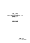
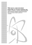
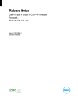
1
FHCS_Max1301HD
User Guide version 1.04
Control your Intelligent Creator Professional Scaler/Switcher System,
Nearby, or remotely…
By Frits Handgraaf, FHCS
August, 2012.
With Dual monitor support, including iPad, Samsung Galaxy Tab and Android PC-Tablet
support via downloadable App’s, and ILS16 or ILS24 connected touch panels.
Copyright, Frits Handgraaf CS.
1
Contents:
Page:
Introduction.
Installation.
Main Startup Window.
Setup communication and scaler application.
- Comm port and baudrate
- Application description, connected products
- Icons/icons
- Icons/backgrounds
- Icons/Button colors
Control Window.
Fine tuning communications and application.
- Extra
- Display
- Display/Monitors
- Learned
- Program
Output windows (scaler).
- Resolution and OSD
- Picture
- Sound
Questions and answers.
3
5
10
11
11
12
13
15
16
20
23
23
24
26
27
28
29
29
32
35
36
Appendix: Optimizing communication speed
39
2
Introduction.
Congratulations with your purchase of the FHCS_Max301HD all-in-one control software
application for the Creator Professional Max1301-HD-B Scaler/Switcher system.
The Creator Max1301-HD-B product allows you to quickly and with high bandwidth quality,
switch Composite video (2 inputs), Component Video (2 inputs), S-video (2 inputs), VGA (2
inputs) and HDMI (4 inputs), upscale each input to high definition progressive scan (up to
WXGA and 1080p HDTV) and output (together with audio input) to VGA and HDMI
connectors, either via the supplied IR remote control or via the front touch panel buttons.
The FHCS software product family is offering an additional product interface based on PC
based interaction, either via PC keyboard, PC mouse interaction or PC connected Touch Panel
(whether pen, stylus, finger, or other), or WiFi connected iPad or Android based Tablet-PC.
This way, ICT-personnel and end-users can optimize the way they want to interact with the
Creator scaler/switcher, in cases the IR remote or front panel interaction is not possible or not
to liking, or if they also want remote control from a distance.
FHCS_Max1301HD allows to:
-
Monitor the attached Creator scaler/switcher. In this way ICT and A/V Presentation
Support personnel always exactly know what the current state of the Creator
scaler/switcher is (with respect to which buttons were pressed via the IR remote or
front panel buttons, or via the FHCS_Max1301HD program).
-
Take over control and scale/switch between input sources and output remotely (over
RS232), with an up-to-date overview of which input channel is connected, and
whether audio, video or both input signals are switched.
-
Move the control window(s) to an attached touch panel or tablet-PC.
-
Adjust or adapt master volume, mute/un-mute master volume, adjust microphone
volume, adjust output resolution, color temp, picture mode, brightness, saturation,
sharpness, contrast, hue or access the system OSD, and more of the embedded features.
-
‘Learn’ actions to be taken when an input button is pressed (“Learned mode”). This
allows to work with just a single button press.
-
Setup applications and application descriptions, including button icons and other
graphics, button colors and window backgrounds. These setups can be stored to file
and later (also automatically) be retrieved and loaded.
-
Adapt the user interface to maximum pixel resolution including resizing of the buttons,
text (fonts) and changing of aspect ratio.
-
Auto-detect the scaler model type and firmware version. After a first connection,
settings are automatically loaded and displayed.
3
-
Auto-detect which RS232 comm ports are available in the PC and starts auto-detecting
on the first port available. You can also select one for communication yourself.
Heart of the program is the setup form, in which the application can be constructed and
adapted to your liking.
In the remainder of this manual all aspects will be further explained.
4
Installation.
The software runs on any (old) PC with a RS232 connector. Supported operating systems are
Windows XP, Vista and Windows7. A minimal amount of disk-space is required (< 12 MB).
FHCS_Max1301HD is licensed software. After installation, a license key is required.
After downloading the ZIP file, Unzip it into an empty directory/folder and run setup.exe.
The following image will appear.
It is important that any running application is closed ! If not, you may experience the program
is not working after installation.
Hit the OK button to go to the next form.
Change the Directory if you so desire or hit the Install Button to accept the default suggested
program Directory.
Note: Hit the button to install it under the FHCS group, see next screenshot.
5
Select the Program Group, default is FHCS, but you can also make a new ILS group.
It may well be that your current PC contains newer files than the ones distributed with this
package. If so, such as in the example above, select Yes to keep the newer file(s).
6
Once the installation is done (and the installation program confirmed a successful installation),
use Windows/start and select FHCS_Max1301HD from the programs folder menu.
After first startup, the program will show the license agreement text.
The license is sold on a per PC basis.
Once you agreed with the license agreement, the program will calculate a product code on
which you can obtain a License Key. This key is required to run the program.
Note: The product code is calculated and different for different PC’s. Only install the
software on the PC of your choice. Another PC will require a different License Key.
7
Enter license key.
After agreeing with the License Agreement, the program will generate a Product Code, with
which you can obtain a License key. The product code is in format ‘ABCD-EFGHIJKLMNOP’, 4-6-6 characters.
Supply your product code to ILS or FHCS to obtain your license-key.
Once you obtained the license key, you are able to run FHCS_Max1301HD after you entered
the license key. This key is based upon internal PC parameters such as first found wired or
wireless network adapter MAC addresses, CPU, Hard Disk drive and other information.
The license key provided has the following format:
ABCD-EFGH-IJKL-MNOP
a combination of characters (in capital) and numbers in a 4 * 4 structure with hyphens (-)
between them. Enter the key including the hyphens exactly as obtained and you will be able to
use the FHCS_Max1301HD software.
Note: Your PC may have more than 1 network adapter. Make sure that the one you want to
use for communication is enabled when the product code is generated.
8
Trying to make a first connection and Auto-Detect.
First start-up.
After a correct license-key entry, the program will try to establish a communication
connection over the first available and free RS232 communication port. It will first check
which comm. ports are available:
If an unused and available Comm port is found (typically Comm1) it will connect to the port
and send out a command to figure out whether the scaler/switcher type is connected and
responding, and what the embedded firmware version is.
This may result to the following image:
The message will show on which Comm port it is trying to detect the device. The program is
waiting for a response during a period equal to CommandDelay + ReadDelay. See later in this
manual on how can change these.
Following is the Main startup window.
Main Startup Window.
From the Main startup window you can determine to go to the Setup window or directly to the
Control window.
Note: If an earlier connection was established successfully, and all Setup parameters are
working to your liking, you can Setup to skip the Main window by adapting one of the settings
in Setup. See later in this manual.
If an auto-detect was NOT successful, it will show up as follows.
Note: In this case, the Control button will not be enabled.
9
Main Startup Window.
Hit the Exit button to exit the program, hit Control to get remote access or Setup to set the
communication parameters or define Applications. In this case, use Setup to make sure we
can make a connection to the Creator Scaler/Switcher...
Note: Always use the Exit button in the Main form or in the Control form to close the
program. This ensures that required parameters are stored to the PC registry. These will be
automatically loaded after next startup.
For contact info, hit the image in the top right.
10
Setup communication and scaler application.
Comm port and baudrate.
In this case, FHCS_Max1301HD found COM1 to be available on the local PC for serial
communications. If you rather use a different port then select it in the list box. Standard
Baudrate for the Creator switcher family is 9600 Baud. In this version of the program you
cannot change that (simply because the Max1301-HD-B setting can not be changed).
Note: If an earlier selected Comm port worked okay, but you want to change it anyway, select
Change Comm in the Extra menu, which will verify available comm. ports again and allows
you to change it.
If you press the Control button at this point, the program will try to communicate over the
specified comm. port and request the Creator model type. If the program does not get a
response, a warning message will appear. Check your connection setup and change the comm.
port accordingly.
11
Application description.
What else can be setup in the Setup form?
See above picture. There is a text box labeled Application description. In here, you can name
your application setup. With the help of Setup, you can totally define the application, which
devices are connected to the input ports, which devices are connected to the output ports,
which ports are factually being used, which icons or other graphics to use in the Control
Window, whether you want to use Learned Mode or manual mode and many more. The
application setup can be stored to a file (and can be retrieved for later use). This way you can
setup different applications for different purposes.
Connected products.
In the connected product section you can determine which ports are being used. Check or uncheck the ports. If the port is un-checked, it will NOT be enabled in the Control window.
In the Connected product text boxes you can describe the type of A/V product being
connected. Examples for input are “Main PC” or “Laptop” (e.g. as VGA or HDMI input).
Basically you can name it anything you want, also in your own language.
The following image shows an example Note that HDMI input 4 is not used (un-checked).
The resulting image now looks as follows:
12
Icons.
Whereas the Main button will return to the Main startup window, and the Control button will
bring up the Control window, the Icons button will allow you to include graphics.
With icons and other graphics you can tune the appearance of the Control window user
interface. Any graphic file can be used for this purpose, including (but not limited to): *.ico
(icon file), *.bmp (bitmap), *jpeg (JPEG file), *.emf, etc.
Note: *.png files are not accepted.
Note: Some graphic or icon files are included with this program as examples. These examples
are downloaded from the Internet.
Note: A demo Application Setup file is included with the package: Demo_Max1301.txt
Hitting the Icons button will bring up the Icons form.
Note that the Connected product description appears in the Icons window to assist in
combining these with the graphic files.
13
The top list view shows the input ports, the bottom one the backgrounds.
In the Icon file name part of the view is the path to the selected graphic file. If you did not
select files before, the entries in the Icon file name column will be empty.
The background file name column shows the location of the selected backgrounds.
How to attach graphics to the command buttons or select a background?
Select a row in one of the views, in this case we selected the 1st input row (Video Casette
Recorder). Buttons Remove, Unselect and File will become enabled.
Select the File button. This will bring up the common dialog so that you can browse to your
desired location. After you selected your graphic file, 2 previews will be filled (right of the
list view). The Picture Top-Left box will show the picture in it’s pixel size. If the pixel size is
too large you will only see part of the picture, in this case the top-left. The Image Compressed
or Stretched box will show a compressed image (if the pixels size is too large) or stretched
image (enlarged).
14
Note: The preview images do not guarantee that the command buttons in the Control window
are large enough to hold the graphic images, but are here to provide an impression and serve
as an aid to see graphic files content.
If there are more buttons you want to populate with graphics, select the next empty row with a
single mouse click.
Note: A double mouse click will bring up the common dialog interface directly so that you are
not required to hit the File button.
If you want to Remove graphics, first select the row in which you want graphics to be
removed, than hit the remove button. The link to the graphics will be removed and the
preview boxes will become empty.
Note: Remove will remove the currently selected (highlighted) row, so be careful that you
are sure when you hit the Remove button.
The Unselect button will unselect the row, to prevent you accidentally remove it.
If the icon file name column is not empty, selecting the row will show the graphic contents.
Selecting another filled column will show the content of that file, earlier content in the
preview box will be replaced.
The graphic links are stored in the application setup file.
Note: Although it is possible to link to graphic files stored on a server on the LAN or from a
USB stick, it might be a better idea to copy them to the controlling PC and use/link them there.
If you Clear Setup (Setup form menu Extra/Clear Setup) also the graphics, or better the links
to the graphic files, are cleared. Graphics are not stored to the registry (but the links are saved
if you save the application setup to a file).
Background.
If you want to change the background of the Control window or the Output window, hit one
of the rows in the bottom listview.
With the File button being enabled, hit it and the file-picker will show up.
You can browse in your PC to select the one you want.
Note: Two backgrounds are included with the package with a resolution of approximate 1280
* 1024.
If your resolution is higher, you may want to stretch it with graphic editors such as Paint.
Note: Recommended backgrounds are in JPEG or BMP format.
15
As with Icons, the selected background preview will be shown in the form.
In this case we selected BlueGreenSun1280_1024 as background for the Control window, and
Blue-Moss_1288_1059 as background for the Output window.
These will be used and shown in the remainder of this user-manual..
Button colors.
Hitting Button Colors will bring up a new Window in which you can adapt the command
button background colors in the Control Window.
16
The buttons are displayed with the current background colors. Underneath the buttons you
find de numeric color value.
Hitting one of the inputs or the output button will bring up the color-picker:
Select the color you want and hit the OK button. The selected button will appear with the new
chosen color.
17
Note: If you selected black as color, the labels above the command buttons in the Control
window can not be read anymore. A message box will appear requesting whether you really
want black.
Hitting the Defaults button will restore the program’s default button colors.
Below and on the following page is an example on what you can do with graphics.
Note that the command button labels are now being relocated to the label above the command
button. This to make place for the graphics.
Note: This image representation is in approximate 800 * 600 pixel resolution.
18
Note: This image representation is in approximate 1280 * 1024 pixel resolution.
Note: Graphic or icon files are not included with this program. Background images can be
created with programs such as PowerPoint or other programs, or by using wall-papers,
photo’s etc. Icon files can be downloaded from supplier web-pages or obtained from their
documentation.
When a background graphic file is used, the background colors in the Input Selector, Signal
Selector and Output boxes will become transparent, so that you can see the background
behind them.
19
Control Window.
On the left side you’ll find the input command buttons, they decide which input source you
want to switch In the middle section you can select which input signal to switch. The 3
buttons allow to switch video only, audio only or both audio and video.
The top middle section shows the current status of the scaler/switcher, that is, which inputs
are connected to the outputs. This status information is reported back by the scaler/switcher.
Note: As no connection was made yet, the Listview is empty.
Note that the command button text is the same as defined in Connected products in the Setup
form.
The buttons under Input Selector are enabled, indicating you can start your input selection.
Note: The Signal Selector buttons (A/V, Video and Audio) will be enabled once you selected
one of the input buttons (Source select).
In this case we selected CV 1 (Video Casette), which can be noted by the label background
color, which is now light blue (conform the output button selected button color). This is the
same light blue as in the Output boxes.
The Signal Selector buttons are now enabled, as is the Cancel button. Hitting the Cancel
button will allow you to select another input source of choice and will disable the Signal
Selector buttons again.
20
After you pressed one of the Signal Selector buttons, the input source (in this case the VCR
on input CV 1) will be switched to the output automatically.
The ‘Signal selection via:’ frame will change accordingly, indicating a switch was performed
by this program (instead of via IR Remote or front panel user input).
The Creator scaler/switcher can also be operated manually via front buttons or via an infrared
remote. FHCS_Max1301HD will also capture changes made by a local operator and indicate
this when applicable in the ‘Signal selection via: ‘ label. Also the status view is automatically
updated.
Next to the Setup button is the communication indicator. This indicator will be light green
when a command is sent to the scaler/switcher and will color dark green if the scaler/switcher
did understand the command and sends feedback. If the indicator colors dark red, the
command was either not understood or commands were sent to quickly (see next session, fine
tuning communications). In that case increase the CommandDelay and/or ReadDelay via the
Extra top menu bar. See also Appendix: Optimizing Communication Speed.
If a connection is established with the scaler/switcher, the Refresh button will be enabled.
You would normally not require the button, but when in doubt it will request a status report
from the scaler/switcher. In the above screenshot, the switcher switched audio input from “CV
2” to the audio output, and switched video from the laptop.
In de Output control section, you have direct control for an attached microphone (increase or
decrease the Mic Volume), Master Volume and Master Mute.
21
Increase the Volume by sliding the scrollbar to the right or by pressing the right scroll button
(>) Alternatively, you can enter the desired volume setting (on a scale of 1 thru 99 under the
scroll bar) followed by an Enter from the keyboard. Hit the Apply button for the (new)
settings to go into effect.
Note: Increasing or decreasing volume will not have an immediate effect until the Apply
button is pressed.
The bottom right section of the control Window will report the currently supported output
resolution in the scaler/switcher. Note: you can specify requested resolution in the Output
Windows, discussed later in this user guide.
The Output button allows you to specify the scaler/switcher output behavior, for each of the
input modes (Composite video, component video, S-video, VGA and HDMI). This includes
Picture mode, Color settings, brightness, contrast and much more. See later in this guide.
Be careful when hitting the Defaults button. This will reset the Max1301HD-B back to factory
defaults. So all changes you may have made in the output windows, will be lost.
What can be changed via the Output window is discussed later in this manual.
Note: A warning message will be displayed requesting if you really want to go back to factory
defaults.
Via the Setup button (Alt-S) you return to the Setup form, where you can further fine tune
communication and application setup.
Via the Exit button you can leave the program.
Note: Exiting the program this way will save parameters to the PC registry. It will however
NOT save any changes you may have made to the Application Setup. Go back to Setup/Extra
and save application setup there.
22
Fine tuning communications and application.
Next to the parameters already discussed, the Setup form allows to further fine tune the
application. This chapter will explain how to do that..
Extra.
If you select Extra (Alt-E) from the top menu bar, the above list comes up. Interactively you
can then change a number of settings:
- Disconnect Comm will close the open communication port. Communication with the
scaler/switcher is no longer possible. You may want to do this if a selected port is not
the correct one.
- Change comm. will interrogate the PC on available comm. ports. These will be listed
in the list box so that you can select.
- Comm OpenDelay is the delay between opening the comm. and actually using the port.
Default is 1000 milliseconds. Some newer PC’s may allow quicker opening.
- CommandDelay is the delay between two commands being send to the scaler/switcher.
Depending on the PC hardware, the connection, and connection distance you can fine
tune this to speed up traffic between PC and scaler/switcher. Default is 1000
milliseconds, but on faster systems 350 milliseconds could be sufficient. See
Appendix.
- ReadDelay is the delay between sending a command and reading the reply. Default is
1000 milliseconds, but on faster systems 350 milliseconds could be sufficient.
- Save Setup will save all the information which was defined in the Setup form to a file.
You can browse to the desired folder (default is the application folder) and specify a
name. The setup will be saved as a text (*.txt) file.
- Load Setup will load a previous saved setup file.
- Autoload can be checked to automatically load the latest saved application setup file at
program start. The location of that file is read from registry. Default is not (checked).
- Clear Setup will clear out the current Setup so that you can define a new one. This will
un-check and clear the Connected product description and all graphics.
23
-
Exit will close the Setup form and return to the Main startup window.
Note: Exit(ing) the Main form will save ‘program’ settings to registry.
Display.
If you select Display (Alt-D) from the top menu, the above shows up.
Debug On will bring up an extra window through which you can monitor traffic between this
program and the scaler/switcher:
If you are familiar with the command syntax, you can also send commands directly to the
switcher. Enter the commands in the Direct command text box and hit Enter (on the
keyboard) or the Send button.
24
If you mark the OSD Deny option, the OSD will not appear on top of the (video) output. If
you want to change output, mark OSD Allow. You can then bring up and access the OSD
menu. Note: The OSD can be accessed in the Resolution and OSD output window.
Via the Resize selection you can specify how the Control window is resizing, e.g. when
hitting the maximize or minimize button or when you drag one of the windows sides with the
mouse. The following form will show up.
Check the Maximize automatically box if you want to resize the Control window
automatically once the program is starting up. Via the Resize frame you can opt for either
Window only or All controls. Window only will leave the original Control window
centralized in the screen while expanding the background to max screen resolution. All
controls will expand to maximum screen resolution taking in account how Aspect ratio and
Font size options are defined. If you want to Apply changes for the next program startup, hit
Apply, go back to the Main form and Exit to save the changes to registry. They will become
into effect once you start the program again.
Note: You can combine this setting with Auto Control in the Program menu. See further in
this document.
The Aspect ratio and Font size options allow you to determine how the Control window is
reacting on mouse dragging form and/or window borders and window max, restore and
minimize buttons. You can basically determine your own screen coordinates, ratio and
whether font sizes should adapt. Here again hit the Apply button. The changes come into
effect when you go to the Control window.
The default Control Window size is an approximate 800 * 600 pixels.
25
Note: Any combination of Resize, Maximize and Aspect ratio and Font size may not lead to
desired results until you restart the program.
Display/Monitors.
Note: This is new in version 1.04.
At program start the application will determine if a second monitor is attached (e.g. extended
desktop). In the example above, a second display is available, with a resolution of 1280 * 752.
Note: In the example above we used a WiFi connected Samsung Galaxy Tab 8.9 Resolution of
this Tablet PC is 1280 * 800 but Android takes 48 pixels off for it’s own purpose.
Note: Using an Apple iPad or Android based tablet PC as extended desktop requires separate
software (App). Here we used ‘Air Display’ from Avatron (avatrom.com).
As the program detected a secondary display, the Secondary Display (extended desktop)
option is being enabled. By checking this option, all program windows will be moved to the
secondary display. If you want to move the Control window only, check the Control Window
Only check box.
Note: Other programs are available to ‘take over’ the desktop, such as Remote Desktop or
LogMeIn. Wyse (wyse.com) supplies an App called ‘PocketCloud Remote Desktop’ which
runs on an iPad. In this case you may want to keep the software on the Primary Display.
The Close button will bring you back to the Setup window.
Hit the Apply button to apply changes being made.
Note: You may have to first startup Air Display and then again this program to get a WiFi
connection, recognizing a tablet-PC is available as extended (secondary) monitor.
26
Learned.
Show List will show the learned command array. If the learned command array was saved
with the application setup, you can show it via Show List. If the list does not exist yet, you
can create it by leaving the Learned Mode checkbox unchecked. Input and signal button
selections will be automatically recorded.
The above list is the result of our actions so far. In the list you find the input number, the
description and whether A/V, V or A is passed thru
Note: Switching audio or video only is represented with A or V respectively.
Clear List will clear the complete list.
So what is learned mode?
27
By checking the Learned Mode box on the Setup form, you only have to select the one input
source button you want in the Control window. Selecting an input source will automatically
also select the signal (A, V, B) and send the required command(s) to the switcher.
By un-checking Learned Mode you can manually specify the switch to perform.
Note: If you want the learned command array to be saved among with the rest of the
application setup, make sure Learned Mode is checked in the Setup form.
Note: If you saved the application setup with the learned command array and load it again in
the future, either manually (Setup/Load) or via Auto load, FHCS_Max1301HD will send
commands to the attached scaler/switcher to bring it back to the stage it was in to when the
application was saved.
Program.
Via Menu Program you can further adapt the way FHCS_Max1301HD is behaving.
Under program you can select:
- Control Hotkey
- Auto Control
You may want to ‘protect’ your communication and application setup from being adapted by
un-authorized users. You can do this via a secret keyboard combination, with Shift, Ctrl, Alt +
function key. Checking the check box and hitting apply will disable the Setup button in the
Main window and in the Control window. Use your keyboard combination to enable the Setup
button again.
By checking the Auto Control menu section, the Control Window will automatically show-up
when the program is started. In this case the Main form and the Setup form will not be shown
(though you can return from Control to Setup in the control window).
28
Output windows.
As described before, the output of the scaler can be adapted by the user. Hit the Output button
in the Control window to access the Output windows. This chapter is describing the
possibilities.
Resolution and OSD.
Via the Output Resolution Combo box you can select the desired output resolution. Choices
are: 800 * 600, 1024 * 768, 1280 * 720 (HDTV 720p), 1280 * 800, 1280 * 1024, 1366 * 768
(HDTV 768p), 1400 * 1050, 1440 * 900, 1600 * 1900, 1600 * 1200, 1680 * 1050 and 1920 *
1080 (HDTV 1080p). Adapt the resolution to best fit with your projector, LCD screen or other
output device connected.
Noise reduction provides a means to filter noise from input to output. Choices are: OFF, LOW,
MID, HIGH and AUTO.
29
Scaling is setting output scaling, being either FULL (16:9), NORMAL (4:3) or AUTO.
LCD Background Color allows to adapt the front panel LCD background color to be either
BLACK or BLUE. Default is blue.
Note: The current (reported back by the scaler) settings are displayed in each frame top right
text box.
Via the LCD Light Time scrollbar you can specify how long (in minutes) the LCD display
will be on after a last front panel selection. Choices are between 0 (off) and 60 minutes.
Default is 15 minutes.
If OSD is set to Allow, and applying background, the windows is as follows:
In OSD (On Screen Display) use the Menu button to show or hide the OSD. With the right
arrow button you go down or right to choose you selection. With the left arrow you go left or
up. Hit Enter to apply your selection.
Via the Control button you return to the Control window.
Hit the Apply button to apply changes made.
Note: Changes made will only be applied (commands send to the scaler) after Apply.
The communication indicator left of the Apply button will change to light green when the
commands are sent, and to dark green if understood and processed. A red communication
indicator tells that one of the commands was not understood.
30
Note: If the communication indicator colors red, try hitting the Apply button again.
If not successful, increase the CommandDelay and/or ReadDelay via the Extra top menu bar.
See also Appendix: Optimizing Communication Speed.
Note: Allow OSD by default is off. However, you can use this feature in this program to
emulate the IR remote functions without remote, and adapt the scaler output settings.
Note: Adapting settings via the GUI as above described, will change the setting with a value
increase of +1 or -1, so give the scaler time to react before you hit the left or right button
again.
Note: The GUI will disappear from the output screen when there is no activity within the set
OSD Duration time.
In the OSD Duration combo box, specify the time in seconds you want the GUI to be
displayed, before it disappears when there is no interaction. Choices are 05s, 15s, 30s and 60s.
Default is 15s.
Via OSD H-Pos and V-Pos you can specify the position of the OSD on the output screen. The
position is expressed in a percentage value, depending on the set output Resolution and the
output Scaling. For example, a set H-Pos to 0, and a V-Pos set to 0, will position the OSD to
the top left corner. Allowed vales are 0 thru 99, with defaults being 50.
Note: You can not change the size of the OSD.
The OSD Halftone setting determines the transparency relative to the displayed background.
Allowed values are 0 thru 8 with 4 as default.
31
Picture.
Via the Picture Tab, you can select the input source for which you want to change settings. In
this case we selected Composite Video.
Note: Note that the frame colors are the same as specified for the Button Colors.
Via Picture Mode you can specify to use pre-defined settings for Brightness, Contrast,
Saturation, Sharpness and Hue. Choices are: Standard, Dynamic, Soft and Personal. When
selecting Personal, the settings under Brightness, Contrast, Saturation, Sharpness and Hue go
into effect.
Allowed values (with the exception of Sharpness) are between 0 thru 99.
Allowed values for Sharpness are between 0 thru 20 with 10 as default.
The Defaults button will restore the scaler default settings, in this case for composite video.
Color Temperature determines the White level in the output. Choices are Normal, Warm and
Cold.
Whether you chose to select the Composite Video, Component Vide or S-Video Tab, the
functionality is exactly the same (and therefore not further described in details in this guide).
In the Picture/VGA Output window, you can adapt the output signal characteristics.
32
If the VGA input and output signal (image) is not well positioned or trembling, you can adjust
via VGA H-Pos, V-Pos, Clock or Phase. Allowed values are 0 thru 99. The AutoAdjust
button will try to adapt the settings via EDID.
Note: Most output devices, like projectors or large LCD screens, have an auto-adjust or autoimage feature. In that case you may not need the AutoAdjust feature of the scaler.
Compared to the Picture (Video) output windows, the HDMI Tab shows 2 more frames:
HDMI Output Mode and HDMI Sound.
33
The HDMI Output Mode option specifies whether to output the digital video output without
sound (DVI) or with sound (HDMI). Whether or not you want the Microphone input to go out
with HDMI depends on your choice of option in the HDMI Sound frame.
34
Sound.
Via the output window Sound Tab you can influence the way the scaler is handling sound
from any of the input sources.
In Sound Mode, you can select: Standard, News, Music or Personal, according to your liking.
Selecting Personal allows to adapt the settings of Set Bass, Set Treble and Set Balance.
Allowed values are 0 thru 99.
Note: The scaler (Firmware version 1.0) is not reporting back personal settings for Bass,
Treble or Balance.
Via Sound AVC you can select: OFF or ON.
Note: When FHCS_Max1301HD started up, and requested the current status for Sound, it
will not get a reply from Firmware version 1.0
Tip: When Sound Mode is set to Personal, increase or decrease the Bass, Treble or Balance
value by a value of 1. The scaler will then report back the changed value and
FHCS_Max1301HD will show the current set value.
35
Questions and answers.
Q: Is the length of the RS232 connection limited to 50 feet (15 meter) ?
A: “Cable length is one of the most discussed items in RS232 world. The standard has a
clear answer, the maximum cable length is 50 feet, or the cable length equal to a capacitance
of 2500 pF. The latter rule is often forgotten. This means that using a cable with low
capacitance allows you to span longer distances without going beyond the limitations of the
standard. If for example UTP CAT-5 cable is used with a typical capacitance of 17 pF/ft, the
maximum allowed cable length is 147 feet.” This is almost 45 meter…
Q: What is the pin-layout required in this direct connection ?
A: Basically required is a RS232 straight through cable. Connect transmit on one end to
transmit on the other and the same for the receive pins (these are pin 2 and 3) and signal earth
to each other (pin 5). So:
2-2
3-3
5-5
As no hardware handshaking is required for the communication, these are the only 3 pins,
from the 9, required.
Q: Which COM port do I have to select in the PC on which FHCS_Max1301HD is installed ?
A: FHCS_Max1301HD will check which COM ports are available in the COM1 – COM9
range. From the available comm ports in the drop-down list, select the one you want to use on
your PC.
Q: Which baudrate setting do I have to select in FHCS_Max1301HD for my PC ?
A: The baudrate setting has to match with the baudrate setting in the scaler. All current
Creator professional audio and video scaler/switchers communicate at 9600 baud only. That’s
why the baudrate in FHCS_Max1301HD can not be changed.
Q: How can I optimize speed between scaler/switcher and PC ?
A: In the FHCS_Max1301HD Setup window, select Extra from the menu. Adapt ReadDelay
and or CommandDelay to lower values. What are the best settings is hard to say and
depending on the line condition and your PC hardware. We have been working with delays as
low as 350 milliseconds. On the other hand, especially if using older hardware or bridging
longer distances, you may need to increase the delays. See Appendix in this guide:
Optimizing communication speed.
Q: What if I want to use a TCP/IP (wired LAN or WiFi) connection instead of RS232 ?
A: That will require special hardware e.g. 2 network adapters (RS232 to TCP/IP).
Q: While in RS232 connection mode, I am not getting a response while trying to Refresh.
Why ?
A: If the scaler/switcher is disconnected or powered off, FHCS_Max1301HD can no longer
communicate. Also verify the RS232 cable connection and the selected comm. port on your
PC.
Q: What do I need to do, to have a loaded configuration setup also switch the desired signals?
A: Make a learned list array. Check learned mode. Save the application setup. When the
application setup is loaded it will automatically switch desired input to desired output.
36
Q: I only have one Scaler. I want to define my application setup only once, so that when
FHCS_Max1301HD is started, my application setup is loaded including my icons and
graphics, my switcher is programmed, the Main and Setup window are not shown (go to
Control directly) and the Control window is maximized to screen size. Can you explain stepby-step how do this?
A: Basically, within the Setup window you can define all this. For this particular case the
steps are as follows (although you can do it in any order except for the first and last 2 steps):
- Connect the scaler via an RS232 cable to your PC. Run FHCS_Max1301HD. If it is
the first time, the program will check which comm. ports on the PC are available and
tries to get a response from the scaler. Change the comm. port in Setup (Extra/Connect
or Extra/Disconnect if connected before) or select a new comm. port from the List.
Change comm. will re-establish this list. Only continue once a connection is
established. You can verify this by going to the Control window and hit the Refresh
button. If the status view is filled, you are okay. If not successful, select another comm.
port. Note: You can use Display/Debug on to see what is sent and received from the
switcher.
- In Setup, fill in the text boxes, e.g. the Application description and the Connected
product textboxes (in the language you want). Uncheck or check the input sources you
want to use.
- In Setup, select Display/Resize. Change the Aspect Ratio from Keep form ratio to
Change form ratio, change Font size from Keep font size to Change font size. Check
automatically in the Maximize frame. Make sure the All controls option in the Resize
frame is selected (this will resize controls to the new window size). Hit the Apply
button for changes to go into effect.
- In Setup, hit the Icons button. Define the Icons or other graphics you want to use with
your Input/Output buttons. Skip this step if you do not want graphics.
- In Setup, select Program/Auto Control to specify the software is automatically
bringing up the Control window, skipping Main and Setup windows.
- In Setup, make sure the Learned Mode check box is UN-checked. Hit the Control
button to get into the Control window. In the Control window, hit each Input button,
and signal to switch, until you are fully satisfied with the Input and Signal selections.
Go back to Setup.
- Back in Setup, select Learned/Make List. This will generate an array based on the
current switcher status and signals to switch. Note: Use Learned/Show List to see the
learned array.
- CHECK Learned Mode. Checking the Learned Mode check box assures everything
which is established so far will be saved into the application setup file, including
descriptions, buttons enabled and graphics associated.
- In Setup, select Extra/Save Setup to save your application setup to a text file (a
common dialog form will show up).
- In Setup, select Extra/Autoload and answer yes. This means that once
FHCS_Max1301HD is restarted, it will automatically re-load the last saved
application setup file.
- Go back to the Main window and hit the Exit button. This will save the complete setup
including the application setup file last used (just defined) into registry.
If you restart FHCS_Max1301HD, the last application setup file, including input and signal
switching, descriptions, icons and graphics and other definitions, become into effect
automatically.
37
Q: Whow! Although the documentation is clear, can you develop application setup files for
me?
A: Yes. Contact [email protected] or [email protected]
Q: With one single license for FHCS_Max1301HD, can I control multiple Max1301-HD-Bs?
A: Yes, in principal you can, as you can save multiple application setups on a mobile PC. In
practice this means you have to carry your mobile PC to the location where the other switcher
is, connect it (RS232) and load/execute the appropriate application setup file (and learned
control array). Note however that your mobile PC can only by connected to one switcher at a
time.
Q: When changing the change automatically in setup/display/resize and going to the control
window, the window does not maximize?
A: This is meant only for resize at startup. After changing the settings and applying, you can
manually change via the Control window max button.
38
Appendix: Optimizing communication speed.
Communication speed is dependent on a number of factors, including medium ( RS232 cable),
distance, PC load etc. By adapting 2 parameters in the Setup Window, one can optimize the
speed between FHCS_Max1301HD (on the PC) and the scaler/switcher. These parameters are
called CommandDelay and ReadDelay.
Command delay is the delay after sending a command before the next command is sent.
Read delay is the delay after first characters from the lectern have been received and before
reading the entire input buffer:
First characters
received
T
Read entire
input buffer
Time >
T + read delay
If ReadDelay is set too low, the input may not be complete. This will result in an error report.
If ReadDelay is set too high, it will take longer to update or refresh the status.
Default for both Command and Read Delay is 1000 milliseconds. Adapt these setting for
optimal results.
For latest documentation, refer to www.fritshandgraafcs.com
End of this User Guide…
39