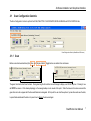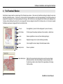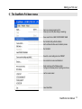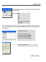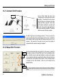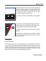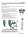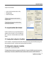
1
ScanWorks User Manual
Revision 1.0
January 2004
PAS129
ScanWorks to Version 2.3.2
Colortrac Ltd.
web • www.colortrac.com
email • [email protected]
UK Kings Hall, St. Ives, Cambridgeshire, UK PE27 4WY
Phone: +44 (0)1480 464618 • Fax: +44 (0)1480 464620
II
ScanWorks User Manual
Copyright Colortrac Ltd
All rights reserved
Offices at:
Kings Hall
St Ives Business Park
St Ives
Huntingdon
Cambridgeshire
United Kingdom
PE27 4WY
17301 West Colfax Avenue,
Suite 165 Golden,
CO 80401 USA
Room 4-B1B, Building #7
Section 3, Century City
HaiDian District
Beijing 100089
China
T: +44 (0)1480 464618
F: +44 (0)1480 464620
T: +1 800 533 0165
F: +1 303 973 7092
T:+86(0)1051 988928
F:+86(0)1051 988927
www.colortrac.com
[email protected]
This documentation may not be reproduced or transmitted in any means, electronic or mechanical, for any purpose, except with the express prior written
permission of Colortrac Ltd.
Colortrac Ltd. makes no warranty claims with respect to this documentation and disclaims any implied warranties of merchantability or fitness for a
particular purpose. The information contained in this document is subject to change without notice. Colortrac Ltd. assumes no responsibility for errors or
omissions that may appear in this documentation.
January 2004
ScanWorks User Manual
III
Overview
1
OVERVIEW .............................................................................................................................................................1
1.1
2
HOW TO USE THIS MANUAL .....................................................................................................................................2
SCANWORKS INSTALLATION............................................................................................................................3
2.1
2.2
2.3
3
SYSTEM REQUIREMENTS FOR SCANWORKS .............................................................................................................3
SOFTWARE INSTALLATION .....................................................................................................................................4
SOFTWARE REGISTRATION .....................................................................................................................................5
GETTING STARTED WITH SCANWORKS ........................................................................................................6
3.1
3.1.1
3.1.2
3.1.3
3.1.4
3.1.5
3.1.6
3.1.7
3.2
3.2.1
3.2.2
3.2.3
3.3
3.4
4
IV
SCAN CONFIGURATION CONTROLS .........................................................................................................................7
Scan ...............................................................................................................................................................7
Filename ........................................................................................................................................................9
Paper Motion Controls .................................................................................................................................10
ScanWorks Units of operation (mm or inches) – Preferences Tab .................................................................11
Paper Size Controls ......................................................................................................................................12
Resolution ....................................................................................................................................................13
DataType......................................................................................................................................................14
FILE FORMAT / PALETTES .....................................................................................................................................15
File Format...................................................................................................................................................15
Palettes – Fixed (in-line processing) .............................................................................................................16
Palettes – Auto (in-line processing) ..............................................................................................................17
MEDIA HANDLING................................................................................................................................................18
DATA CONTROL (THE SCANNER INTERNAL SETTINGS) ............................................................................................21
THE THUMBNAIL WINDOW .............................................................................................................................22
ScanWorks User Manual
Overview
5
THE VIEWING DESKTOP...................................................................................................................................23
5.1
THE ‘LOUPE’
AND SCREEN DISPLAY MODES .........................................................................................................24
6
THE TABS INSIDE THE EDITING CONTROLS AREA ...................................................................................25
7
EDITING CONTROL AREA (COLOR AND IMAGE EDITING CONTROLS) ...............................................26
7.1
7.2
7.3
8
FILTERS AND CONTROLS FOR RGB AND GRAYSCALE.............................................................................................26
FILTERS AND CONTROLS FOR 256 COLOR (OR INDEXED COLOR) .............................................................................28
FILTERS AND CONTROLS FOR 1-BIT COLOR OR BLACK AND WHITE (BINARY COLOR) ................................................28
MAKING YOUR FIRST SCAN.............................................................................................................................29
8.1
8.2
8.3
CHECKING THE SETTINGS .....................................................................................................................................29
SAVING YOUR FIRST PRESET .................................................................................................................................29
STARTING THE SCAN ............................................................................................................................................30
9
THE SCANWORKS PULL DOWN MENUS........................................................................................................33
10
SCANNER MAINTENANCE ................................................................................................................................35
10.1 SCANNER CLEANING ............................................................................................................................................35
10.2 STITCH MAINTENANCE .........................................................................................................................................35
10.2.1
Automatic Stitch Procedure ..........................................................................................................................36
10.2.2
Manual Stitch Procedure ..............................................................................................................................36
10.3 WHITE CALIBRATION OR NORMALIZATION ...........................................................................................................39
10.3.1
White balance...............................................................................................................................................39
10.3.2
Light normalize only ....................................................................................................................................39
ScanWorks User Manual
V
Overview
11
MORE ADVANCED TECHNIQUES – IMAGE CONTROLS ............................................................................41
11.1
11.2
11.3
11.3.1
11.4
11.4.1
11.5
11.5.1
11.6
11.7
11.8
11.9
11.10
11.11
11.12
12
MONOCHROME SCANNING – INTERACTIVE DYNAMIC THRESHOLDING...........................................58
12.1
12.2
12.3
12.4
13
ADAPTIVE THRESHOLDING IN BLACK & WHITE. ...................................................................................................59
BASIC THRESHOLDING IN BLACK & WHITE ...........................................................................................................60
DITHERED THRESHOLDING IN BLACK & WHITE ....................................................................................................61
DESPECKLING WITH BLACK AND WHITE SCANNING ...............................................................................................62
FLATBED SPECIAL EDITING CONTROLS (MORE CONTROLS)................................................................63
13.1
13.2
VI
SHARPEN / BLUR .................................................................................................................................................42
NOISE REDUCTION...............................................................................................................................................43
RGB CURVES EDITING ........................................................................................................................................44
Exploring the ScanWorks RGB curve editor.................................................................................................45
BRIGHTNESS - CONTRAST ....................................................................................................................................47
Using the ScanWorks Brightness / Contrast curve editor .............................................................................48
BLACK / WHITE POINT .........................................................................................................................................49
Using the Black – White Slider ....................................................................................................................50
DESKEW..............................................................................................................................................................51
ROTATE ..............................................................................................................................................................52
CROP ..................................................................................................................................................................53
MIRROR ..............................................................................................................................................................54
CONVERT TO . . . ..............................................................................................................................................55
RESAMPLE........................................................................................................................................................56
INVERT ............................................................................................................................................................57
4 POINT JOIN TOOL .............................................................................................................................................63
OVERLAY JOIN TOOL ...........................................................................................................................................66
ScanWorks User Manual
Overview
13.3
13.4
DESKEWING WITH THE OVERLAY JOIN TOOL .........................................................................................................67
CUT OVERLAP TOOL ............................................................................................................................................68
14
4 -TIER AUTO INCREMENT FILE NAMING ...................................................................................................69
15
PRINTING FROM SCANWORKS .......................................................................................................................70
16
PAPER STAGING ADJUSTMENT ......................................................................................................................71
17
SCANWORKS BATCH PROCESSOR .................................................................................................................72
17.1
17.2
17.3
17.3.1
17.4
17.5
17.6
18
COLOR CLASSIFICATION .................................................................................................................................76
18.1
18.2
19
RUNNING UNATTENDED (AUTO-SAVE)..................................................................................................................72
RUNNING WITH OPERATOR PRESENT (QUALITY CONTROL MODE)...........................................................................72
USING PRESETS WITH SCANWORKS BATCH COMMAND ..........................................................................................73
The Batch Command interfaces....................................................................................................................74
USING THE SCANWORKS BATCH SCHEDULER ........................................................................................................75
CREATING A BATCH CONFIGURATION IN SCANWORKS ...........................................................................................75
EDITING A BATCH CONFIGURATION IN SCANWORKS ..............................................................................................75
REDUCING A FULL COLOR SCAN TO 64 OR FEWER COLORS .....................................................................................76
COMBINING AND CHANGING COLORS IN A SCAN .....................................................................................................77
APPENDIX .............................................................................................................................................................79
19.1
19.2
19.3
19.4
HARDWARE INSTALLATION – (SKIP THIS SECTION IF YOUR SCANNER IS ALREADY INSTALLED) ..................................79
FIREWIRE PRECAUTIONS ......................................................................................................................................79
COMPUTER HARDWARE RECOMMENDATIONS .........................................................................................................79
IEEE-1394 PCI CARD INSTALLATION...................................................................................................................79
ScanWorks User Manual VII
Overview
19.5
19.6
19.7
19.8
19.9
19.10
20
VIII
FIREWIRE PLUGGING PRECAUTIONS ......................................................................................................................79
CABLE LENGTH ...................................................................................................................................................79
COLOR DEPTH FILE SIZE CALCULATIONS (WITHOUT COMPRESSION) ........................................................................80
SCANWORKS LICENSING LIMITATIONS ..................................................................................................................80
TURBO MODE BUTTON.........................................................................................................................................80
IMPORTANT CABLING INFORMATION ....................................................................................................81
INDEX ....................................................................................................................................................................82
ScanWorks User Manual
Overview
1
Overview
ScanWorks has been designed to convert large format images retrieved by Colortrac scanners into digital form and store this on an attached
computer - as easily as possible.
ScanWorks represents a revolutionary software approach to managing the scan to file process for large format scanning. Unlike most other
scanning software available today which use an ‘adjust and rescan’ method to perfect settings for more difficult originals, ScanWorks can do all this
with a single scan by emulating scanner behavior on the computer. When the scan has been adjusted on-screen the scan (which is already on disk)
is overwritten as the Save button is clicked. By activating the inline function these adjustments can be incorporated automatically in all further scans
or saved as a Preset. This not only saves valuable time and boosts productivity but it also reduces wear and tear on the original document.
The concept of ScanWorks was arrived at by listening carefully to the needs of scanning professionals and continues to be enhanced regularly to
accommodate the constantly changing requirements of the large format scanning market.
ScanWorks software is designed to work with all Colortrac products from the single camera Colortrac 3640e to the Colortrac 24120 Flatbed
scanner right up to ANAtech Eagle high-resolution products like the 42160C.
“ We hope that you too will find ScanWorks a pleasure to use.” – Peter de Winter-Brown (Sales & Marketing Director, Colortrac Ltd.)
ScanWorks User Manual
1
Overview
1.1
How to use this manual
The manual is divided into five Chapters
Chapter 1. Overview (this section)
How to use this manual, the sections and coverage of the manual
Chapter 2. Software Installation and Graphical Interface –
The ScanWorks system requirements, software installation from the Colortrac CD and the ScanWorks
Graphical User Interface with descriptions and locations of all the main controls
Chapter 3. Making your first SCAN –
The steps to making your first Colortrac scan
Chapter 4. Advanced Scanning –
More Advanced Techniques – Image Controls
Chapter 5. Appendix –
Notes on the hardware installation, FireWire cable lengths and file sizes.
Help and Assistance:
Throughout this manual you will see that some text appears in shaded blocks. These areas provide assistance in the form of the QUICKSTART
TIP which is a summary of the main configuration steps, the TIP which is experienced based operator information for faster and more accurate
scanning and a NOTES heading where you can find further explanatory detail.
2
ScanWorks User Manual
Software Installation and Graphical Interface
2
2.1
ScanWorks Installation
System requirements for ScanWorks
The Colortrac scanner sends data to the computer via a SCSI (Small Computer Systems Interface) or FireWire (IEEE-1394) connection. Although
it is possible to connect the scanner using both of these connections at the same time, DO NOT do this. If using a SCSI connection (for example
for NT4) it will be necessary to purchase an adapter card such as Adaptec 29160 or similar with the appropriate cable.
ScanWorks V230 and later is only available for the more recent Windows operating systems - see below. To use ScanWorks for earlier operating
systems like NT4 it will be necessary to use the SCSI connection method because FireWire was not supported by NT4. Windows 98 First Edition
is not compatible with ScanWorks version 2 upwards. Windows 98 Second Edition will work with ScanWorks but like NT4 does not properly
support a FireWire connection. Note that under NT4, SCSI will need the appropriate ASPI layer installed for the adapter card in use. To use a
SCSI card with the operating systems listed below no ASPI layer installation is necessary because these operating systems use the later STI (Still
Image Interface) to communicate with the scanner. STI is built into these operating systems and no additional software is required.
Supported operating systems:
Windows 2000, Windows 2000 Professional, Windows XP, Windows XP Home
Recommended computer hardware:
Pentium 4, 2.4 GHz or better with at least 256MB of RAM and 40GB of hard disk space. A slower
computer may not allow the scanner to achieve the maximum speeds as published in the specifications.
Display settings:
The graphics resolution should be set to 1024 x 768 or higher and color depth to full-color, 24-bit color or
32-bit. A 17” monitor is the minimum size recommended for comfortable operation of the graphical user
interface (GUI).
ScanWorks User Manual
3
Software Installation and Graphical Interface
2.2
Software installation
Insert the Software Installation CD that ships with every scanner into the computer you intend to use with your new Colortrac scanner. If the
Software Installation Disk splash screen does not pop up right away you may need to right-mouse click and choose AutoPlay, or alternatively use
Explorer to double-click the Launch.exe file in the root of this CD. Click install software and then proceed to select the operating system used on
your computer.
NOTE: You will need to use Administrator privileges to first install ScanWorks. After installation, users with limited privileges will still be able to
use the software but will not be able to remove or re-install the ScanWorks product.
4
ScanWorks User Manual
Software Installation and Graphical Interface
2.3
Software registration
Colortrac Ltd. operates a policy of continual product improvement. ScanWorks application software is shipped free of charge with the scanner to
each Colortrac customer *. Normally, as updates and new versions become available, these can be downloaded free-of-charge from the Colortrac
ftp site, Colortrac web site, or can be obtained from your local Colortrac distributor. If an update copy of ScanWorks is required and needs to be
sent by post then Colortrac will usually make a small charge for this service.
Colortrac will keep you informed of updates and new
products unless you expressly wish not to be
contacted.
If you do not wish Colortrac or their
representatives to contact you please check the last
radio button before clicking
to transmit the
form.
A copy of this manual and a browser based
Frequently Asked Questions area (FAQs) is available
on the Colortrac website. For more help and advice or
technical service assistance, please contact your local
Colortrac dealer or distributor.
www.colortrac.com
* January 2004
ScanWorks User Manual
5
Software Installation and Graphical Interface
3
Getting Started with ScanWorks
The ScanWorks user interface has four
main areas.
•
The scan configuration controls
•
The overview window
•
The editing control area
•
The viewing desktop.
REWIND / STOP
EJECT / STOP
Scanner panel controls
6
ScanWorks User Manual
Software Installation and Graphical Interface
3.1
Scan Configuration Controls
The Scan Configuration Control is split into the SCAN, PALETTES / FILE FORMATS, MEDIA HANDLING and DATA CONTROL tabs
Scan Configuration Controls (ScanWorks v2.30 shown)
3.1.1
Scan
Before a scan has been started only the Scan and Single or Batch. Toggle buttons are visible in the control area.
The green Scan button has three functions. During scanning the Scan button icon will change to display a red SCAN Stop icon. Pressing it now
will STOP the scanner. Work already displaying on the viewing desktop can be saved at this point. When the document has been scanned the
green Scan icon will re-appear with the Save and Delete icons alongside. At this point the user has three options; to press Save and save the data,
to press Delete and discard the data or to press Scan to Rescan the document again.
ScanWorks User Manual
7
Software Installation and Graphical Interface
SCAN (F9 from the keyboard)
The file has been named and the user is ready to start scanning. NOTE that the
Delete and Save icons are not present before the scan has been started.
All
information in the view desktop is true image data at the resolution set up in the
scanner configuration controls. A full scan and not a prescan has been made.
STOP (F10 from the keyboard)
During scanning, the scanner can be stopped by clicking the SCAN Stop icon on
the ScanWorks interface, or by pressing either of the scanner panel Rewind or
Eject buttons.
RESCAN (F9), SAVE(F11) or DELETE (F12 from the keyboard)
When the scan has completed the user has the option to Rescan, Save or Delete
the current image on the viewing desktop
Until the Save button is pressed all Colortrac scanners store scan data using a temporary file name. Pressing Save instructs the operating system
to apply the name provided by the user to scanned data. Because all of the data is already saved by the time the document stops moving
ScanWorks control is returned to the operator very quickly after the Save icon is pressed (except when the scan has been modified post-scan).
TIP: The scanner model number and internal program (firmware) release is shown in brackets to the right of the word Scan on the first tab of the
scan configuration controls. This information will only be visible when the scanner is switched on and ready to scan.
8
ScanWorks User Manual
Software Installation and Graphical Interface
3.1.2
Filename
Manual and Simple Increment
Press the
icon to manually name your file. This button also permits the operator to browse, create folders and even rename files via the
right-mouse click menu.
In single scan mode the Colortrac scanner will require the user to input the file name before pressing Scan - unless the user starts the automatic
naming process by ending the name with a hyphen followed by a numeric sequence. For example a scan file name typed in as bracket-03 and
then Saved would cause ScanWorks to automatically generate the next file name as bracket-04. This will continue until ScanWorks detects an
identical filename in the same directory.
4-Tier Auto Increment
Press the
icon to configure automatic incremental numbering for your scan filename.
If you used the -nn file naming format above, pressing this icon will display the 4-tier file naming dialogue. Use this feature to create counter-driven
names for your scan files. For example: contract-02drawing-49 can be generated by inputting the appropriate start and end point for each
counter. The counters work in a similar way to vehicle odometers except that the number at which any higher order counter will be advanced is not
limited to 10. This feature can be used with single scan or Batch scanning operations (see next section).
QUICKSTART TIP: Press the . . . icon and type a name
UICKSTART TIP: Press the . . . icon and type a name
QUICKSTART TIP: Press the . . . icon and type a name
ScanWorks User Manual
9
Software Installation and Graphical Interface
3.1.3
Paper Motion Controls
Pressing this button toggles its operation between manual start scan mode and automatic start scan mode - often called Batch scanning
mode. In Batch scanning mode ScanWorks will automatically begin scanning the second and all following documents without the user
pressing the Scan icon. The user only needs to load each document and ScanWorks will take over the naming, saving and eject
processes automatically. Batch Scanning is dealt with in more detail later in the manual.
Clicking the upward arrow (F7) when the document is stopped will cause the scanner to eject the document with sub-options to hold or
release (see Data Handling tab covered later). Use of the hard panel rewind or eject buttons during a scan will Abort the scan and stop
the scanner. The scan can now be resumed from the stopped position by clicking the Scan button. Alternatively the document can be
ejected or rewound (and staged) from the ScanWorks interface (F8), or manually ejected using the panel control buttons.
If ScanWorks shows the Scan button, Rewind, and Eject buttons lit, then the scanner is ready to be
used.
If the scanner is switched off or not connected to the computer, ‘No scanner attached’ will be
displayed and the Scan button will be grayed out.
Scanner icon displayed during Batch Mode (automatic mode)
QUICKSTART TIP: Use manual start mode (not automatic batch mode) to begin scanning
10
ScanWorks User Manual
Software Installation and Graphical Interface
3.1.4
ScanWorks Units of operation (mm or inches) – Preferences Tab
The Preferences Preset provides user access to:
ToolTips........................Balloon help giving basic guidance on the control or
button under or near the current cursor position
Units..............................Set ScanWorks to Metric or Inches. All measurement
will display and require input using these units.
Temporary files path This is the location reserved for all temporary storage
required by ScanWorks.
Language......................Language setting for ScanWorks
A language change becomes
effective after a program restart.
Scale to gray ................For Black and White scanning.
Makes small detail visible when
viewing the whole drawing
onscreen.
QUICKSTART TIP: Always use the local hard disk as the temporary drive. Colortrac also recommend for all network based scanning
that scans be stored first locally and then transferred to the network afterwards.
ScanWorks User Manual
11
Software Installation and Graphical Interface
3.1.5
Paper Size Controls
Standard size
Use the browse box to select the paper size closest to the size of the document you are
about to scan. Paper sizes larger than the physical document will be cropped on length
automatically by the scanner and can be width cropped by the operator as required.
Paper sizes set smaller than the physical document will capture this area of the
document from the point at which the scanner starts moving.
Automatic size
Check this button to have the scanner automatically detect the document size. Note that
for some compressed file formats a full prescan will be required prior to beginning the
scan. For most formats only a short document feed is used to find the width of the
document with the length detected as the scan completes. Documents can be placed
anywhere along the throat of the scanner as long as one of the document sensors is
activated
Specify size
Useful for non-standard paper sizes where automatic sizing may be too slow. Also for
fragile documents it can be better to specify a larger size and then manually crop it using
the editing tools rather than selecting Auto. Auto will rewind the document before
scanning it, risking possible to worn or fragile documents.
QUICKSTART TIP: Change Paper size to Standard and select the same or next size up. Use the ruler when Specifying paper size
12
ScanWorks User Manual
Software Installation and Graphical Interface
3.1.6
Resolution
The Colortrac scanner is available in various model types. These vary according to their width and optical resolution. The model number is related
to these two parameters in the following way. The Colortrac 3680e is used here as an example.
3680e
denotes enhanced scanner design (introduced October 2002)
the optical resolution doubled and divided by ten
(In this example optical resolution is 400 dpi)
The active scan width of the scanner in inches
(In this example 36” or 915mm)
PRESET scanner resolutions can be selected by the user from (optical resolution / 8 *) dpi up to
twice the optical resolution (in this example 800 dpi).
Higher interpolated resolutions can be
generated using the custom settings entry up to a maximum of 2400 dpi ( 6 times the optical
resolution) using interpolation techniques. High interpolated resolutions can place extra demand on
computer resources.
* Minimum selectable resolution is 50 dpi
QUICKSTART TIP: Answer the question: “ What resolution do I need for this scan?”
ScanWorks User Manual
13
Software Installation and Graphical Interface
3.1.7
DataType
DataType describes how the color mode of the Colortrac scanner is set. For example as
a full color device; a limited color scanner, a grayscale or a simple black and white
scanner. This is also known as the Color Depth of the image. All Colortrac scanners
use 32-bit primary point data capture as the basis for all color scanning.
RGB means full photographic quality color. This is sometimes referred to as 24-bit or 16
million colors.
256 colors (available as fixed or automatically derived). Useful for maps and schematic
drawings and posters where fewer colors can be used without degrading the appearance
rd
of the image. Images created with this mode will be approximately 1/3 the size of RGB
scans (uncompressed).
16 color (available as fixed or automatically derived). Useful for maps where there are
th
only perhaps 4 colors. Images created with this mode are 1/6 the size of RGB scans
(uncompressed).
Grayscale creates 256 shades from white to black. This file will be the same byte size as
a 256 color file.
Black and White reduces an image to a single color, black. All other colors or shades of
gray are turned off or discarded. The level at which data is accepted is called the
threshold. Adaptive Thresholding is an advanced technique to deal with large areas of
original where there is low contrast making normal basic thresholding less effective.
256 Mono and B&W Mono produce the same results as grayscale and Black & White
except that they are derived by taking the digital information from a single color channel
(green). The effect of this is to triple the scan speed of the scanner. Do not use for
black and white scans for images containing green information, as this may not scan
properly.
QUICKSTART TIP: Change DataType to RGB
14
ScanWorks User Manual
Software Installation and Graphical Interface
3.2
3.2.1
File Format / palettes
File Format
ScanWorks uses TIFF (Tagged Image File Format) as its default file format. This file format can be used to store digital scan information from
small binary black and white images (10-20MB) to large full color images (600MB plus). Not all formats are available for all color modes.
Clicking on the second tab, File formats / palettes, reveals an area where the file format for each DataType (Color Depth) choice can be set.
See the Appendix for more information on Turbo Mode.
Turbo Mode button
Use the scroll button control at the
right-hand side of the DataType
boxes to pull down the formats
available. NOTE: TIFF is available
for all DataTypes.
The settings used in one or all of
these menus can be stored in
ScanWorks Presets.
QUICKSTART TIP: Change RGB Scan file type to TIFF
ScanWorks User Manual
15
Software Installation and Graphical Interface
3.2.2
Palettes – Fixed (in-line processing)
The Palette section of the second tab is dealt with here and after File Format (3.2.1) because it is less important for users who are just getting
started with color scanning. Palettes enable a scanner to produce image files with fewer overall colors. A full color scan with16.7 million colors is
wasteful of disk space to capture a map with just 32 base colors. Fixed palettes assign the actual color in the original to the nearest color in the
palette. The fixed palette may often be unsuitable for a map with many similar colors. Colortrac supports 256 and 16 fixed color palettes.
Note that the sea area of the map is speckled with blues of quite
different intensity. This is because the scanner is taking the color at
this point and forcing it into the best category it has. Fixed palette
scanning is most effective when scanning a set of documents for
which a palette has been derived automatically – see next section.
NOTE: Inline means processed by the scanner instead of in
the computer. This can benefit slower computer systems.
16
ScanWorks User Manual
Software Installation and Graphical Interface
3.2.3
Palettes – Auto (in-line processing)
When the scanner is set for Auto palette the resulting scanned colors are much closer to the colors in the original. For best results a 16 color map
will need to be scanned using a 256 color palette because pure colors are never pure and begin to fade and change slightly over time.
Note that the scan color quality produced when the scanner carries out
an autopaletted scan is much better than the result from the fixed
palette scan. The scanner achieves this by first taking a lowresolution full color prescan of the original. From the prescan, it
analyses the colors to find out which ones are important and considers
their coverage of the image area. These details are then processed to
make the new optimized palette. The palette is then downloaded to the
scanner and used for the final scan at the resolution set by the user.
The result is a much closer and finely balanced image that is nearly as
good as full color but occupying 66% less storage space. Palettes
generated from an auto palette scan can be saved as the fixed palette
using the “Convert to” tool dialog. Useful for scanning multiple
documents that are similar such as quad maps. No need to need to
auto palette each one separately!
TIP: Always set DataType for 256 colors(Auto) or 16 colors(Auto) when using auto-paletting
ScanWorks User Manual
17
Software Installation and Graphical Interface
3.3
Media handling
This tab controls whether the scanner should eject the media after the operator SAVEs or DELETEs a scan. It is also the tab where the speed of
the scanner can be controlled to match the performance of the computer. For the best scanning results, rapid stopping and starting of the scanner
should be avoided by lowering the speed setting of the scanner if required. This will not affect overall scan time and productivity.
End of scan behavior
Rewind on Save/Delete...............After the scan completes clicking Save or Delete will rewind the document
Eject on Save/Delete...................After the scan completes clicking Save or Delete will Eject the document to the rear of the scanner
Do nothing on Save/Delete..........After the scan completes clicking Save or Delete will leave the document at its current position
Auto detect end of media ............The scanner will detect the end of the media
For most file formats and a paper length set oversize the scanner will produce a digital document
matching the physical length of the document by detecting its length as it scans. The width will remain as set.
No prescan is needed. Scanner behavior is identical for Standard or User defined sizes.
For most file formats and Auto paper size selected the scanner will determine first the width and detect
the document length as the scan is completed. No prescan is required.
For some file formats auto detect has no effect and ScanWorks must either be used with a known paper
size or paper size must be determined prior to the scan proper through the automatic Prescan operation. The
Autosize Prescan is carried out by ScanWorks when AutoSize is selected for some formats that involve
compression, see Table on page 20. Note that in V230 Hold and Detect are overridden if the user specifies a
document size in excess of the physical document size.
18
ScanWorks User Manual
Software Installation and Graphical Interface
Hold checked ..............................The document FORWARD WINDS in scan direction after an EJECT but remains gripped in the scanner
Hold unchecked ..........................The document is released by the scanner after an EJECT and the document falls to the floor or tray
Justification
Center .........................................Scan documents by placing them in the center of the scanner (better for irregular media)
Side.............................................Scan from the side using the raised edge (good for smaller documents)
Staging
Start ............................................Increase or reduce the scan start point on the leading edge by + / - 12mm (see Section 16)
End .............................................Increase or reduce the scan start point on the trailing edge by + / - 12mm (see Section 16)
Speed
Speed 1.......................................(slowest)
Speed 8.......................................(fastest)
Alter the scan speed if necessary to keep the scanner running continuously and to avoid stop/ start scanning
which can lead to poor image quality through the production of image artifacts, blurs or spectrum effects.
Auto load delay.........................The time interval between the scanner detecting the document and taking it from the operator at the start of the
loading or staging operation.
Disable auto load ......................Turn off automatic paper loading. This will add approximately 68 mm (2.7”) of white space to the top of the scan
and will require that a larger paper size is specified to allow for the lost length in the scan. Usage: Position media
in the scanner making sure to contact the paper sensor before starting the scan. Optionally the operator can use
the feed button to part-load the document to grip it more firmly before pressing scan. Excess area around the
scan can be removed using the crop control.
For fast document overrun scanning with manual paper load make use of F9 to scan and F11 to save, or use
Batch Scan Set Detect off, Do nothing, Hold off. Set a generous paper size. Scans will include a ‘white’
boundary which must be cropped. Advantages: fast throughput.
QUICKSTART TIP: Click Do nothing, check HOLD, choose CENTER, FAST and a load delay of 1 second
ScanWorks User Manual
19
Software Installation and Graphical Interface
End of Media / Autosize Behavior Table for ScanWorks 2.3.2 or higher:
Format
CALS
JPEG
JPEG2K
PCX
PDF
PICT
PNG
SUN
TIFF G3
TIFF G4
TIFF JPEG
TIFF PACKBITS
TIFF RAW
WMF
•
•
RGB
256 color
16 color
Grayscale
Black and White
Green: Line count is updated in real time (just like uncompressed tiff).
Red: Behaves as before, either filling the remainder of scan with white or prescanning entire document for autosize.
Note that PNG (Portable Network Graphics) files, a popular Microsoft graphics standard and supported by all the major Microsoft
applications, can be used with full autosize or end of media detect support. This means that for an unknown size of document a fulllength Prescan is NEVER necessary.
20
ScanWorks User Manual
Software Installation and Graphical Interface
3.4
Data control (the scanner internal settings)
This tab provides control of Brightness, Gamma and selection of raw RGB scanning or sRGB (standardized RGB) scanning. Use of sRGB
provides corrected color output suitable for standard Windows peripherals like monitors and color printers. Certain colors may scan better with
sRGB turned off.
Brightness ....................Controls the amount of white in the scanned image (default value depends on the scanner model)
Gamma..........................Controls the depth of the colors seen by the scanner (default values are 1.5, 1.5, 1.5 for R G and B)
sRGB.............................Standardized RGB color scanning according to the Microsoft/ Hewlett-Packard standard. See Appendix detail.
NOTE: The scanner Brightness and Gamma settings are not intended to be changed by the user and have been set to
the optimum values for the machine. This assumes the scanner has reached its operating temperature (after 30
minutes) and has been recently White Calibrated (or normalized). For more help on this procedure, see the Scanner
Operator and Installation Manual for Colortrac Scanners.
Calibration
White Balance................Sets the dark (R=G=B=0) point and white (R=G=B=255) point for the scanner (normalization)
Light normalize only........Performs a white balance only (does not turn the lamps off ensuring fully warm tubes)
Auto Stitch .....................Automatically align all cameras using the card stitch target - does not apply to 3640e
Manual stitch..................Operator driven stitch dialogue to set the overlap of the cameras. See Section 10
Use Adaptive Stitch........Have the scanner correct for very small L / R errors during scanning (primarily for Colortrac 24120)
QUICKSTART TIP: Select sRGB and make sure the scanner has been on for 30 mins and has been white calibrated before scanning
ScanWorks User Manual
21
Software Installation and Graphical Interface
4
The Thumbnail Window
ScanWorks will always make the scanned image fit the Thumbnail view window. At the same time ScanWorks will begin to display the same scan
data filling the Desktop window. If the Zoom in controls under the Overview window are used the image displaying in the Desktop window will
enlarge but the image size in the Overview window will not change. After the first zoom a red rectangular Zoom Indicator will be displayed in the
Overview window indicating the section of the main image which has been enlarged and now fills the Desktop window. As the zoom is repeated
the Desktop view becomes +larger while the Zoom Indicator shrinks.
22
1:1 zoom
No magnification (1 pixel in the file is displayed as 1 pixel on the screen)
Fit to Window
Fits the image to the window (sometimes call zoom extents) – default zoom
- zoom
Reduce magnification or zoom out (Zoom indicator gets larger)
+ zoom
Magnify the image or zoom in (Zoom indicator gets smaller)
Loupe
Use to magnify the scanner image in the desktop viewer window
Hand pan icon
Move in any direction.
Zoom Indicator pan
Right-click the zoom indicator and drag to pan across the scanned image
(fastest pan method).. Also click and drag out a square (marquee) in the
thumbnail view window to have that part of the image display in the Viewing
Desktop window.
ScanWorks User Manual
Software Installation and Graphical Interface
5
The Viewing Desktop
The ScanWorks Viewing Desktop window is a ‘Live’ view of the original image at the resolution set in the scan configuration controls. This means
that the scan can be inspected for completeness (no missing edges) in the first view of the original as it appears onscreen. Next it can be viewed at
1:1 to very rapidly quality check the image – all in one single operation. This is a Colortrac productivity feature.
All scan data is directed immediately to the viewing
desktop where it can be inspected, cropped, rotated or
deskewed using the Editing Controls.
Use the horizontal and vertical sliders at the sides of the
Viewing Desktop to navigate around the scanned
image. Alternatively, click the
control
below
the
thumbnail view to activate the hand-panning tool. The
Zoom controls can be used with the hand-panning tool.
Use the hand pan to move the zoomed image in any
direction. Use the left click to zoom in and the right click
to zoom out
TIP: Use the top pull-down Window menu to arrange multiple scans on the Viewing Desktop – tile vertically, horizontally or cascade
ScanWorks User Manual
23
Software Installation and Graphical Interface
5.1
The ‘Loupe’ and Screen display modes
The Loupe tool permits the operator to quality check the scan as
it first appears with greater freedom to change the zoom using
the right-click of the computer mouse. It can be moved over the
full image and the zoom altered by clicking the right mouse
button. Toggle the Loupe icon to turn this feature ON and OFF.
The Loupe window can be resized by dragging the edge of
the circle. The loupe window will also display what ever is
beneath the cursor when the cursor is positioned outside
of the loupe window.
The main viewing desktop can be switched to fill the whole
screen by clicking on the small arrows in the view window left
margin. Clicking the same arrows again, (toggling) will restore
the viewing window to the Standard display size with the full
editing and file controls visible.
Top graphic shows the Loupe magnification set to 200%
Lower graphic shows ScanWorks set for Full Screen display
mode. Clicking the arrows in the left border toggles each
display between Standard and Full Screen mode.
View Controls available in Full Screen Display Mode
24
ScanWorks User Manual
Software Installation and Graphical Interface
6
The Tabs inside the Editing Controls Area
Presets
Clicking this tab reveals the Presets available. These can be altered and deleted by the user as required.
Controls
This tab brings up the Editing controls relevant to the currently selected color mode or DataType of the scanner
(for example Full Color RGB, Black and White, Grayscale or Indexed Color)
More Controls
classification
This tab reveals further controls for running external editors and indexing programs as well as the Color
module of ScanWorks for color separation and feature extraction. When a Colortrac 24120 Flatbed scanner is
connected extra icons appear in this tab. See Section 13 for more detail on the flatbed editing controls.
Preferences
Use this tab to set the units used inside ScanWorks, the Language, the location of the temporary files, the Tool
Tips status and to enable/ disable Scale to gray.
ScanWorks User Manual
25
Software Installation and Graphical Interface
7
7.1
Editing Control Area (color and image editing controls)
Filters and Controls for RGB and Grayscale
These controls allow the scanner operator to alter the RGB or Grayscale image shown in the Viewing Desktop Window WITHOUT rescanning the
document. The operational concept behind ScanWorks is that the image can be edited in front of the user as required and then if necessary these
changes can be made automatic (or ‘IN-LINE’) for all subsequent scans. Examples of IN-LINE editing can be simple operations like Rotation and
Inversion of the image (changing white to black and black to white) to more complex operations like Sharpening or altering the Black and White
Points.
Sharpening........................Improve the focus of text and fine lines. Start with +1
Blur....................................Soften the focus of photographic details
Noise Removal ..................Remove spurious effects and image aberrations. Particularly
Filter
useful for removing moire effect produced by halftoned
originals. Also useful for dust and speckle removal.
NOTE: Sharpening and Denoise filters are only relevant for
full color (RGB / 24-bit) and
grayscale scanning modes.
ScanWorks
may
display
different or fewer tools for the
other scan modes.
RGB Controls....................Alter the intensity of R G and B using color curves
Contrast.............................Increase / decrease image contrast
Brightness .........................Increase / decrease image brightness
White point ........................Combines the white end of the spectrum
Black point.........................Combines the black end of the spectrum
Deskew .............................Adjust the image to line-up horizontally or vertically
26
ScanWorks User Manual
Software Installation and Graphical Interface
Filters and Controls for RGB and Grayscale - contd.
Grayscale is very similar to full color or RGB 24-bit when a single color channel is considered. Full color scanning uses the Red, Green and Blue
channels each with 256 levels. The grayscale scanning mode uses 256 levels but using a single ‘color’ K or black. In the Colortrac scanner
grayscale can be generated by using the output from all three R,G and B cameras or by just using the G camera – so-called greenscale scanning.
Greenscale scanning is three times (3x) faster than ordinary Grayscale scanning.
Rotate image........................ Rotate through 90, 180 or 270 degrees
Crop image .......................... Delete unwanted border data from the image
Mirror ................................... Mirror the mage about the y-axis
Color Depth.......................... Change 24-bit to 256 to 1 bit (binary)
Reduction
Resample............................. Reduce the resolution of the scanned image
Invert.................................... Change white for black (blueprint scanning)
ScanWorks User Manual
27
Software Installation and Graphical Interface
7.2
Filters and Controls for 256 color (or indexed color)
When ScanWorks is being used with the scanner in 256 or 16 color the Sharpening and Noise Removal filters are NOT available
The sharpening and noise removal filters only work with RGB (24–bit full color) or grayscale scan data
7.3
Filters and controls for 1-bit color or Black and White (binary color)
When ScanWorks is being used to run the scanner in Black and White mode some of the color only filters will disappear from the tool group. Black
and White scanning introduces the Despeckle and Dynamic Threshold controls (see below)
Despeckle ............Remove isolated pixel groups (speckles)
Dynamic ...............Produces Black and White scans by processing grayscale
thresholding
data in the computer using Basic or Adaptive thresholding
28
ScanWorks User Manual
Making your first scan
8
8.1
Making your first SCAN
Checking the settings
ScanWorks settings checklist
Scanner checklist
Scan icon is green inside ScanWorks
DataType = RGB
Paper sizing = Standard, size = A4 portrait
Paper position = Center
Resolution = 200 dpi
sRGB = ON
End of scan = Do nothing
Filename = TEST or similar
Speed = Fast (*)
Load delay = 1 second
Scanner has been switched on for 2 minutes (ideally allow 30 min)
Scanner has passed its stitch procedure (3640e does not apply)
Scanner has been white calibrated with a clean target
Light on scanner lid is showing green
The scanner document illumination tubes are lit - look through the gap
where documents are loaded or exit the scanner.
8.2
(*) denotes default setting
Saving your first Preset
The Preset option in ScanWorks is provided to allow the
user to capture any mix of settings. It is useful practice to
save these settings now so they can be reloaded at any
time during the scanner familiarization and training period.
Note that whenever ScanWorks is closed it will reload
with the settings that were in use when it was shutdown.
If the program terminates abnormally, no settings will be
saved. Reloading this Preset will restore the settings
shown above.
ScanWorks User Manual
29
Making your first scan
All saved Presets can be listed by pressing the Presets tab in the editing
controls area. As the user changes to other presets the ScanWorks
settings linked to that preset alter in the ScanWorks interface. Once
selected the database details for Image type, Media, Condition and Scan
are displayed in the lower panel.
The Labels in any preset can be changed to reflect the nature of the
scanning work being carried out by selecting the existing text and re-typing
a new label.
Presets can be changed by selecting the Preset, making the ScanWorks
setting changes and selecting Save current settings as preset in the
ScanWorks File menu.
8.3
Starting the scan
•
Place the document on the scanner in the center of the paper tray, face down with the top of the document nearest the rollers and
allow the document to load (assumes Center justify selected). The Flatbed 24120 takes media side justified to the panel corner.
•
Now using the cursor, click the SCAN
•
•
•
30
button or press F9 on the keyboard to begin scanning.
(The very first sRGB scan configures the scanner and will always be slightly slower than for repeated sRGB scans)
Review the image shown in the viewing desktop
If the image is OK press the Diskette icon (or F11) to save the image. The document will remain gripped in the
scanner. For production scanning change the End of scan setting to ‘Eject’
Press Rewind to reload the same document ready for further self-training. (The paper setting can be reset to Eject after training)
ScanWorks User Manual
Making your first scan
The SCAN Workflow
SCAN REQUIRES CROP OR
EDITING OPERATION
(OPTIONAL)
SCAN / F9
?
DISCARD SCAN
(NAME RETAINED)
ADJUST SETTINGS / CHANGE
DOCUMENT (NAME RETAINED)
DELETE OR DISCARD / F12
SAVE SCAN
TO DISK
SAVE SCAN
TO DISK
SAVE / F11
SAVE / F11
ScanWorks User Manual
31
Making your first scan
The BATCH SCAN Workflow
SCAN / F9
?
PAUSE/ EDIT
CANCEL (FINISH)
BATCH
INTERRUPT SCAN FOR
CROP OR EDITING
OPERATION
(OPTIONAL)
SAVE SCAN
TO DISK
SAVE / F11
32
SCANNER
AUTO LOADS AND
AUTO SAVES
DOCUMENTS PLACED
IN SCANNER
CURRENT SCAN
DISCARDED AND
SESSION ENDED
ScanWorks User Manual
Making your first scan
9
The ScanWorks Pull down menus
..................... Open any previously saved scan file
................................................... Close any current file (after editing or reworking)
................................................... Save current file to a NEW OR DIFFERENT NAME
................................................... Run the Batch utility within ScanWorks
................................................... Add to or Delete the files used in the Batch process
................................................... Run the Batch
................................................... Save ALL current settings to a User PRESET
................................................... Use current scan as an email attachment
................................................... Send current view to the Windows printer
................................................... Configure the Windows printer for printing current view
................................................... Last four scans loaded
................................................... Leave ScanWorks
ScanWorks User Manual
33
Making your first scan
UNDOs are multiple and operation sensitive. This means they change to reflect the type of editing operation
currently being undertaken.
For example UNDO Deskew
Crop
Rotate
Mirror
Sharpen
Blur
Type conversion (a reduction to fewer colors)
Reduce resolution
NOTE: To undo a recent RGB or black-white adjustment (to the brightness or RGB curves) the RESET button on the tool dialogue must be used.
If a scan has been made with a tool active as an inline device IT CANNOT BE UNDONE. Scans in this case will need to be rescanned with the
relevant tool switched off.
The Window Menu provides access to:
...................................................... Cascade the scans inside the Viewing Desktop
...................................................... Tile horizontally all scans inside the Viewing Desktop
...................................................... Tile vertically all scans inside the Viewing Desktop
........ Line up minimized scans inside the Viewing Desktop
................................................ About: - Version number of ScanWorks
34
ScanWorks User Manual
Making your first scan
10 Scanner Maintenance
10.1 Scanner cleaning
Although the Colortrac scanner will not be affected by dirt on the optics aperture, it is always a good idea to regularly check the scanner rollers and
paper surfaces for signs of dirt and grease. These can be cleaned with non-solvent based computer equipment foam cleaner or similar. Also
check the surface of the paper pressure plate inside the lid of the scanner for deep scratching as this may affect the quality of transparency scans.
If you expect to be scanning large quantities of drawings covered with abrasive dust, it is a good idea to remove most of the surface contamination
before placing them in the scanner. Any dust that falls through the aperture will not pose a serious threat to image quality because it will not settle
in the focal plane (at the aperture) nor is it likely to land in a position obstructing a vital pixel. If you suspect that there is a dirt build up on the
mirrors that is affecting the image, a white calibration will often cure the problem. If you suspect an object has fallen into the scanner and is
causing a serious problem please contact your nearest Service Agent for assistance.
10.2 Stitch maintenance
All Colortrac scanners with the exception of the 3640e have two or more CCD (charge-coupled devices) cameras which are combined optically to
look at the total width of the scanner aperture – usually 36”, 42”, 48” or 54”. The point where any two camera images meet is called the stitch point.
Apart from an obvious side-to-side alignment, there is also a front-to-back alignment. After transporting the scanner or when the scanner is
exposed to excessive temperature fluctuations, these fine alignments may need re-setting. This is done using the Stitch Target supplied with the
scanner. If the target is lost or damaged the process can be performed manually within the software. No physical attention is required within the
scanner and the whole process is electronic and only takes a few minutes.
ScanWorks User Manual
35
Making your first scan
10.2.1 Automatic Stitch Procedure
P/N:P001218-2
From the Data Control tab move to the
Calibration section and click the button marked
Auto Stitch. This will prompt the user to place
the Stitch Target on the scanner at the center
position and then to press OK. Note: Check
that the target is positioned in accordance with
the mark at the top of the target specifying the
Colortrac model being calibrated. The process
will take a couple of minutes to complete.
The Stitch Target has four black triangles printed on it. These are used by the
scanner to electronically achieve perfect alignment of the scanner. Note that the
stitch calibration data his stored inside the Colortrac scanner and not in the
computer. This ensures that the scanner can be moved from computer to
computer without the operation needing to be repeated.
10.2.2 Manual Stitch Procedure
F/B
L/R
36
Still using the Automatic Stitch target, place this in the scanner in exactly the
same way and choose the Manual Stitch button from the Calibration section
menu. Note that it does not matter how ScanWorks is currently set (for example
in color or black and white) since using the Scan button on this panel will set up
automatically the correct settings for the procedure. When the image onscreen
is complete, click the View boundary 1 button to see the image from two
adjacent cameras.
Note: scanners with three cameras will show three pairs of sliders (4280e and
5480e)
ScanWorks User Manual
Making your first scan
Screen shot (left) shows the left camera (camera 1 when viewed from underneath the paper)
is displaying low and indicating a single pixel error. This is called a Front/ Back stitch error.
NOTE: Always use a horizontal edge to detect a Front/ Back stitch problem and correct it by
raising or lowering the vertical slider in for the appropriate camera. Rule: If the camera on
the left is showing low increase the slider value for that camera.
CAM 1
CAM 2
1
2
CAM 1
CAM 2
The Front / Back error should always be corrected BEFORE any Left / Right adjustment is
made.
The second screenshot is a view of the diagonal part of the polygon showing a Left / Right
stitch overlap. This shows the left camera apparently too far over the right camera. This is
corrected by INCREASING the value shown by the horizontal slider for Camera 1.
The red dotted line indicates the amount of horizontal movement needed to correct the Left /
Right stitch error.
After stitching the scanner, it is advisable to carry out a white calibration or normalization.
This will ensure that all cameras record equal intensities of black and white across the total
active scan width of the scanner.
NOTES ON STITCHING
Q1.Why is re-stitching necessary?
A1.For scanners that use CCDs, lenses and mirrors, stitching will most likely never be totally eliminated. However because of the
unique way in which the Colortrac is designed and manufactured re-stitching should not be needed on a frequent basis. If the scanner
is subjected to rough handling or large and rapid temperature changes it is a good idea to check the stitch alignment using the stitch
target. If the scanner loses stitch regularly or it cannot be aligned because there is no adjustment left in the sliders, this is an indication
that the cameras have moved or become loose and a trained service engineer should be contacted.
ScanWorks User Manual
37
Making your first scan
After automatic or manual adjustment of the stitch values it is advisable to verify the
scanner stitch settings using the stitch target. In some circumstances, it may be
necessary to make the adjustment by altering the opposite side of the affected pair.
In other words if a Front / Back stitch was attempted using the camera on the left of a
camera to camera intersection then instead move the camera on the right side of the
intersection. An identical approach can be used on the Left / Right stitch.
CAM1
CAM1
CAM2
CAM2
To check the stitch settings on a Colortrac scanner always scan in grayscale at the
optical resolution of the scanner. The view boundary button on the Manual Stitch
dialogue can be used to zoom into the stitch area for closer inspection.
Graphic showing correctly adjusted Left / Right (top) and Front / Back (lower) stitch
boundaries.
CORRECTLY STITCHED CAMERA BOUNDARY
38
ScanWorks User Manual
Making your first scan
10.3 White Calibration or Normalization
White Calibration or Normalization (sometimes also called white balance) is the name given to the procedure when all cameras used in the scanner
have their upper and lower limits aligned to the maximum and minimum values. When red, green and blue mix at full strength they produce white
light. White light is given the value 255,255,255 in other words 100% of R G and B is present. When there is no light this is seen as 0,0,0 or 0%
of R G and B – in other words black. A White balance is in fact a white and a black balance and both operations are carried out when a scanner is
normalized.
10.3.1 White balance
Carefully remove the Calibration Target (white acrylic sheet) from inside the scanner lid by opening the lid to its rest position and then sliding the
target sideways. Clean the target if necessary with a normal window cleaning solution or similar. Pull back both Height Setting Sliders to position 5
and insert the target into the back of the scanner so that the rear edge is level with the back curve of the scanner lid. Now click the White balance
button. The procedure will turn the scanner lights on and off while moving the target backwards and forwards slightly in the rollers. The software
will prompt the operator to remove the target when the operation is complete. DO NOT FORGET TO REMOVE THE WHITE TARGET
10.3.2 Light normalize only
It can save time to only adjust the light end of the scanner spectrum sometimes. Clicking ‘Light normalize only’ keeps the lights turned ON. This
saves time because there is no need to wait for the lights to reach full brightness after they are turned OFF for the dark calibration part of the full
‘White balance’ operation. Learn how to recognize whether your scanner needs normalizing by reading the notes below.
Q1. Why Normalize?
A1. Normalizing is used to correct the change in the illumination intensity along the length of the fluorescent tubes used inside the Colortrac
scanner. During their lifetime (normally about 1 year) the quality of the ‘whiteness’ can change, particularly at the ends of the tubes. Normalizing
also corrects for small variations in the color sensitivity of the CCDs used in the scanner although special checks are made to match CCDs during
scanner manufacture.
ScanWorks User Manual
39
Making your first scan
Q2. How often should I Normalize the scanner?
A2. Users should normalize the scanner at least every week for color work. For black and white scanning it is not as important but still a good
idea to repeat on a regular basis to maintain the high quality achievable with the Colortrac scanner. Black and white scanning relies on
processing grayscale data that can be affected by a badly normalized scanner.
Some documents may not have a perfectly white background. This will produce background color information for a scanner calibrated to
perfect white using the target. If not needed as image information, background data will increase the size of the scan file and increase printing
times so it is usual for it to be removed. It can be removed during the scan or as a post-scan editing operation using the ScanWorks White
point editor (see Advanced Image Editing). Another way to solve this problem and one that can give a more natural result is to calibrate the
scanner with a paper stock similar or the same as the image to be scanned. This will cause the background to be ‘seen’ as pure white and lost
from the image. There must of course be no shades lighter than the background level or these will be lost.
NORMAL documents:
As soon as originals containing white information are required the scanner must be either Light Normalized or given a
full White balance to restore calibration back to the optimum values.
CURSOR RGB:
ScanWorks provides a continuous readout of the Red, Green and Blue values of every pixel of the image. This can be
used to monitor the normalization of the scanner. Below left shows low RGB (dark gray), below right shows high RGB
(white). The RGB readout is given at the current cursor location.
RGB 81,66,69
40
RGB 242,244,246
ScanWorks User Manual
Advanced Scanning
11 More Advanced Techniques – Image Controls
The Inline (Auto) and Reset buttons - IMPORTANT
The unchecked INLINE button. Each edit function has its own Inlne (Auto) button. Checking this button causes
ScanWorks to automatically apply the tool in real time or at the end of the scan.
The checked inline button means that automatic editing is ACTIVATED and ScanWorks indicates the ACTIVE control
using a green or yellow outline border. A green border indicates processing during the scan. A yellow border means
the action is applied automatically after the scan has completed.
An activated Sharpen / Blur control
An activated Rotate control (rotation is carried out after the full image is scanned). Inline (post) button displays a red bar
An often overlooked control, the RESET button is more than a simple slider reset. Clicking this button adjusts the size
of the Crop Box and Deskew tools to suit the current zoom.
The images to the right show the
Crop Box before and after resizing
to suit the current Zoom.
ScanWorks User Manual
41
Advanced Scanning
11.1 Sharpen / Blur
The Sharpen / Blur Control set for
Sharpen1. This control has a 1:1 Preview
button which can show the user how the
image can expect to look after the filter has
been applied on the portion of the image
visible in the viewing window (auto zoomed
to 1:1).
When the required amount of filter has
been found the Sharpen / Blur button is
clicked to process the whole image. The
image will now need to be saved to store
the Sharpened form of the image.
Notes / recommendations:
For the Sharpen control use a setting of 1
to bring up 200 dpi maps to a sharper
more focussed result without the disk
space implications of using a higher
resolution.
Blurring affects all detail in a scan.
Sharpening is effective at 1:1 and low
zooms for example copies
The ‘enabled’ but borderless ‘A’ icon tells
the ScanWorks operator that the tool is
being applied interactively.
The green INLINE button and green border
around The ‘A’ button indicate that the filter
is being applied during the scan.
This is a ‘Virtual Scan Tool’ and when used
offline this edit tool produces the same
effect as when used ‘Live’ during the
scanning process. In manual use, the
result of the edit replaces the image shown
in the viewing window.
42
Normal
Blurred –1
Sharpen +1
ScanWorks User Manual
Advanced Scanning
11.2 Noise Reduction
The Noise reduction Control set for 3x3.
This control has a 1:1 Preview button
which can show the user how the image
can expect to look after the filter has been
applied on the portion of the image visible
in the viewing window (auto zoomed to 1:1).
When the required amount of filter has
been found the De-noise button is clicked
to process the whole image. The file will
now need to be saved to store the Denoised form of the image.
Notes / recommendations:
Use where there are print screening
problems – usually where the resolution of
the scanner ‘interferes’ with the resolution of
the printed original.
Maintains detail and removes screening
patterns without losing sharpness.
Use of this control in-line will slow down
scanning depending on the resolution used.
The ‘enabled’ but borderless ‘Waveform’
icon tells the ScanWorks operator that the
tool is being applied interactively
The green INLINE button and green border
around The ‘Waveform’ button indicate that
the filter is being applied during the scan.
This is a ‘Virtual Scan Tool’ and when used
offline this edit tool produces the same
effect as when used ‘Live’ during the
scanning process. In manual use, the
result of the edit replaces the image shown
in the viewing window.
Blur –1
DeNoise 7
Normal
ScanWorks User Manual
43
Advanced Scanning
11.3 RGB Curves Editing
The RGB Curves Editor. This can be used
to control the intensity of the primary
scanner colors of Red, Green and Blue.
This control Previews the effect of altering
the curves in real-time and updates the
image in the viewing window.
When the required amount of filter has
been found the image can be saved to
store the effect of the filter on the original
image.
The ‘enabled’ but borderless ‘Curves’ icon
tells the ScanWorks operator that the tool
is being applied interactively.
The green INLINE button and green border
around the ‘Curves’ button indicate that the
filter is being applied during the scan.
This is a ‘Virtual Scan Tool’ and when used
offline this edit tool produces the same
effect as when used ‘Live’ during the
scanning process. In manual use, the
result of the edit replaces the image shown
in the viewing window.
44
Notes / recommendations:
This control can be used to increase the
color saturation of the image being
scanned or in the editor.
The characteristic ‘S’ curve is often used
to strengthen colors in a scan.
A filter although SET will not be active for
any scan unless the INLINE arrow or
green border are showing. To apply the
setting manually to a scan ‘click’ the
slider control or curve grips.
Use this control with a single color
selected to change the intensity of this
color in the scan. For example remove
blue or increase red to add warmth to an
image.
ScanWorks User Manual
Advanced Scanning
11.3.1 Using the ScanWorks RGB curve editor
Neutral RGB
Saturation
OUT
IN
Linear filter setting applies no
changes to the red, green
and blue signals. There is
no increase or reduction in
the gamma of the scan data.
Alter the RGB values as a
group or individually as red,
green or blue
De-saturate
OUT
IN
The curve is dragged low to
increase the saturation of
all colors. Note how the
background has darkened
and the lighter shades are
now lost as the midtones
are lost.
S-curve
OUT
IN
For a low input there is
high output. This will
mean a movement of the
colors to white as the red,
green and blue signals
get larger (nearer 255).
Weaker colors get
brighter
OUT
IN
Used to lighten the
background and the lighter
colors while improving the
contrast and general color.
Colours in the mid tones
are boosted. Very light and
very dark colours are not
affected much
ScanWorks User Manual
45
Advanced Scanning
Using the ScanWorks RGB curve editor continued . . .
46
Neutral Red
Low Red
High Red
Low Green
The red channel is selected
as the channel to be
adjusted. The green and
blue channels will not be
affected by any adjustments
to the red curve
The red curve is dragged
low to reduce the red
components of the scan
The red curve is dragged
high to increase its
intensity allowing it to
dominate over blue and
green
The green curve is dragged
low to reduce the green
component s of the scan.
Blue and red are stronger
ScanWorks User Manual
Advanced Scanning
11.4 Brightness - Contrast
The Brightness and Contrast slider pair.
This control Previews the effect of altering
the sliders in real-time and updates the
image in the viewing window.
When the required amount of filter has
been found the image can be saved to
store the effect of the filter on the original
image.
The ‘enabled’ but borderless ‘BrightnessContrast’ icon tells the ScanWorks
operator that the tool is being applied
interactively
The bright-green INLINE arrow and green
border around the ‘Brightness-Contrast’
button indicate that the filter is being
applied during the scan.
Notes / recommendations:
The Brightness control can be used to
bring out shadow information. It can also
be used to compensate for ageing tubes
in the scanner as the scanner gets older.
Contrast will take out subtle information
leaving only the strong colors
A filter although SET will not be active for
any scan unless the INLINE arrow or
green border are showing. To apply the
setting manually to a scan move the
slider control(s).
This is a ‘Virtual Scan Tool’ and when used
offline this edit tool produces the same
effect as when used ‘Live’ during the
scanning process. In manual use, the
result of the edit replaces the image shown
in the viewing window.
ScanWorks User Manual
47
Advanced Scanning
11.4.1 Using the ScanWorks Brightness / Contrast curve editor
Brightness controls the amount of white in a scan. Contrast controls the tonal quality of an image
48
Brightness High
Brightness Low
Contrast High
Contrast Low
High brightness moves every
color towards white and
effectively puts more white
into the images
Low brightness takes white
out of an image and makes
the image much darker.
This is not the same as
saturating or decreasing
the gamma
Contrast exaggerates the
divisions between colors
by removing any tonal
quality. Colors move
towards their primary
state – C M Y K R G B
and Black
Low contrast softens the
divisions between colors
eventually making the entire
image gray
ScanWorks User Manual
Advanced Scanning
11.5 Black / White point
Showing the Black Point control set to 194
and the White Point control set to 15.
These controls Preview the effect of
altering the sliders in real-time and will
update the image in the viewing window.
When the required amount of filter has
been found the image can be saved to
store the effect of the filter on the original
image.
The ‘enabled’ but borderless ‘Black+White
dot’ icon tells the ScanWorks operator that
the tool is being used by the operator
interactively.
Notes / recommendations:
Use White-point to remove unwanted offwhite backgrounds from scans.
Use Black point to increase the purity of
black information in scans. Be careful
not to over use as they will increase the
harshness of an image if used
excessively.
A filter although SET will not be active for
any scan unless the INLINE arrow or
green border are showing. To apply the
setting manually to a scan move the
slider control(s).
The bright-green INLINE arrow and green
border around the ‘‘Black+White dot’ button
indicates that the filter is being applied
during the scan.
This is a ‘Virtual Scan Tool’ and when used
offline this edit tool produces the same
effect as when used ‘Live’ during the
scanning process. In manual use, the
result of the edit replaces the image shown
in the viewing window.
ScanWorks User Manual
49
Advanced Scanning
11.5.1 Using the Black – White Slider
For grayscale and full color images. This control collects grays and off-whites together.
50
Low White Point
High White Point
White Point can be used to
remove background
grayness. Note the light
shades are lost in the center
of the image
Aggressive White point will
remove all the lighter
shades because they have
a large white value
Low Black Point
A low Black Point can be
used to darken black
detail, however it can
sometimes make text
appear blocky and
unnatural
High Black Point
A high Black Point groups
all colors except the lighter
shades.
ScanWorks User Manual
Advanced Scanning
11.6 Deskew
The Deskew Control set for 0.54 degrees.
This is an interactive control and requires
the operator to identify the longest
horizontal or vertical line in the image and
for them to place the Deskew marker ends
onto each end of the line.
When the required amount of deskew has
been found the Deskew button is clicked to
process the whole image. The file will now
need to be saved to store the Deskewed
form of the image.
The direction of the deskew rotation is
determined automatically by ScanWorks
but can be entered manually (overidden) by
the operator
Press to re-size Deskew
reference line to fit current
zoom
Notes / recommendations:
Use where the image is not oriented
perpendicular to the viewing window.
Where possible always re-scan the
document instead of carrying out a
deskew.
If you must deskew the image and need
to refine the process do not deskew an
already deskewed image - always UNDO
a deskew and start again for a better final
result.
ScanWorks does not support anti-alias
deskewing and some post-deskew image
irregularities may be visible at high zoom
factors.
Deskew is interactive and must be carried
out by the operator.
TIP: At minimum zoom, roughly stretch the ends of the deskew tool to each end of the longest horizontal or vertical line in the image. Now zoom
into the drawing over one end and affix the deskew marker. Now, by making a right mouse click, drag the thumbnail area of interest to move the
zoomed area along to the opposite end of the line being used as the deskew reference. Affix the second marker. Finally click the deskew button
to complete the deskew.
ScanWorks User Manual
51
Advanced Scanning
11.7 Rotate
The Quadrant Rotate Control set for 90
degrees clockwise.
This function can be set INLINE (by
clicking the green arrow) to automatically
rotate every scan image. The graphic left
shows this feature in manual mode.
The ‘enabled’ but borderless ‘icon tells the
ScanWorks operator that the tool is being
used by the operator interactively.
Notes / recommendations:
Use to rotate an image. Useful to rotate
by 90 degrees A0 drawings which are
being scanned SEF (short edge first) in
the scanner. After processing, rotated
drawings will present LEF (long edge
first) or landscape in the viewing window.
Use of this control in-line can slow down
the overall scan time depending on the
resolution used.
The speed of this
process is also affected by choice of file
format. Compressed file formats (for
example TIFG4) will take longer to
process.
The bright-green INLINE arrow with the
RED bar above and yellow border around
the ‘Rotate’ button indicates that automatic
image rotation has been selected. Note:
Rotation in fact occurs automatically
directly after the scan finishes
52
ScanWorks User Manual
Advanced Scanning
11.8 Crop
The Crop Box.
Notes / recommendations:
This is a realtime manual control and
performs the conversion in the viewing
window.
When the required amount of crop has
been decided upon the operator
presses Crop to cut away all image
data OUTSIDE of the crop margin.
The ‘enabled’ but borderless ‘Crop’
icon tells the ScanWorks operator that
the tool is being used interactively.
Use to quickly clean up irregular edges of
any scan. If you crop too much you can
undo with ScanWorks – how many times
will depend on the memory in the
computer.
Remember to use the RESET button to
resize the Crop Box and grips to fit your
zoom instead of manually zooming out to
find them.
This tool is NOT available as an
automatic feature.
Press to re-size Crop box
to fit current zoom
ScanWorks User Manual
53
Advanced Scanning
11.9 Mirror
The Mirror Control.
This is a realtime manual control and
performs the conversion in the viewing
window.
This is a ‘Virtual Scan Tool’ and when used
offline this edit tool produces the same
effect as when used ‘INLINE’ during the
scanning process. In manual use, the
result of the edit replaces the image shown
in the viewing window.
Notes / recommendations:
Use for transparencies where the
‘printed’ side closest to the CCDs during
scanning must be revolved about the yaxis.
The ‘enabled’ but borderless ‘Mirror’ icon
tells the ScanWorks operator that the tool
is being applied interactively.
The bright-green INLINE arrow and green
border around the ‘Mirror’ button indicates
that the filter is being applied during the
scan.
54
ScanWorks User Manual
Advanced Scanning
11.10 Convert to . . .
The Convert to Control set for 256 colors.
Step down to file formats with lower Color
Depth or fewer colors.
If the image
showing in ScanWorks was scanned in
RGB then all of the shown reductions will
be possible. The Color Depth may be
changed in steps manually (always towards
the fewer color version) or by skipping
intermediate levels if required as an inline
process.
The ‘enabled’ but borderless ‘Checker’ icon
tells the ScanWorks operator that the tool
is being used by the operator interactively.
The bright-green INLINE arrow with the
RED bar and the yellow border around the
‘Checker’ button indicates that the filter is
being applied after the scan.
Notes / recommendations:
Use to convert Full color scans to files
with fewer colors to reduce file size.
Use to change color scans to grayscale.
Use to change grayscale scans to binary
(black and white)
Use of this control in-line will incur extra
processing time after the scan and
depends on the resolution used and the
size of the image.
This is a real-time manual control and
performs the conversion in the viewing
window.
TIP: Conversion allows colour scans to be reduced to files of fewer colours and smaller byte size at
medium to high resolution and is suitable for maps, schematics and similar. Not effective for
photographic images where it is preferable to reduce the resolution and use JPEG or JPEG2000 to
reduce scan file size instead.
ScanWorks User Manual
55
Advanced Scanning
11.11 Resample
The Convert to Control set for 256 colors.
Notes / recommendations:
Step down to lower resolutions to reduce
the file storage size of the scan.
Use to make smaller file sizes. Use this
feature to produce scans for wordprocessing documents where high zoom/
close-up detail is not required.
Resample is not available as an offline
function and must be carried out by the
operator.
This is a real-time manual control and
performs the conversion in the viewing
window.
The ‘enabled’ but borderless ‘Checker’ icon
tells the ScanWorks operator that the tool
is being used by the operator interactively.
TIP: Resampling a scan from 400 dpi down to 72 dpi will reduce the byte size (the area) of any scan by a factor of 72/ 400 x 72 / 400 or 0.032.
The physical dimensions will be approximately 0.18 of those previously in each of the axes. For scans intended to be viewed on a monitor, 72 dpi
is a good general resolution which maintains both legibility and keeps the storage size of the document to a minimum.
56
ScanWorks User Manual
Advanced Scanning
11.12 Invert
The Invert Control.
Notes / recommendations:
Use this control to move any shade of black
through white to the opposite end of the
gray spectrum. Turn blacks to white and
white to black.
Use where the scan is produced the
wrong way around in a black and white
sense.
For example
engineering
blueprints where the background will
scan as black and the foreground or line
information as white.
This is a ‘Virtual Scan Tool’ and when used
offline this edit tool produces the same
effect as when used ‘Live’ during the
scanning process. In manual mode, the
result of the edit replaces the image shown
in the viewing window.
The ‘enabled’ but borderless ‘Invert’ icon
tells the ScanWorks operator that the tool
is being used by the operator interactively.
The bright-green INLINE arrow and green
border around the ‘Invert’ button indicates
that the filter is being applied during the
scan.
ScanWorks User Manual
57
Advanced Scanning
12 Monochrome scanning – Interactive Dynamic thresholding
The Colortrac scanner is an excellent monochrome scanning device. Monochrome scans are very small in storage format terms and can occupy as
little as 250 Kbytes for an A0 1189 mm x 841 mm drawing when compressed using 2D TIFF Group 4 compression. Engineering plans and
drawings are converted into raster format and emailed rather than sending a hard copy. TIFG4 is also a very common file format and compatible
with most viewers such as Kodak Imaging, Paint and many others.
Select :
DataType = Black & White or Black & White Mono (high speed Green channel mono)
Resolution = 200 dpi
The Black & White Threshold Control
Notes / recommendations:
This is a ‘Virtual Scan Tool’ and when used offline
this edit tool produces the same effect as when
used ‘Live’ during the normal scanning. In manual
mode the result of the edit replaces and
continually updates the image shown in the
viewing window.
Use to produce very small binary files
which store only ON (binary 1) or OFF
(binary 0) data.
The Black and White thresholding control can be
set to produce Basic, Dither or Adaptive output.
Black and White Thresholding is a filter that
works permanently to produce BW data in the
scanner or in the computer. When thresholding is
selected for in computer ScanWorks (termed
“Post-scan threshold) provides interactive control
over the thresholding levels for Basic and
Adaptive methods. ‘Virtual Thresholding’ permits
optimization of the image while only needing to
scan ONCE.
Use Basic Thresholding for clean
drawings with no background noise or
dirt.
Use Adaptive Thresholding for drawings
where the background density
approaches the foreground (lines) and
contrast between the two is poor.
Do not assume Adaptive thresholding is
always best. Do not leave it switched on
for clean drawings.
TIP: Post–scan thresholding or in-computer thresholding allows INTERACTIVE adjustment without rescanning
58
ScanWorks
User Manual
Advanced Scanning
12.1 Adaptive Thresholding in Black & White.
1.
2.
3.
4.
5.
Enable Post scan threshold in the top of the Black and White controls dialogue
Select Adaptive. Post scan thresholding causes grayscale data to be returned to the computer.
Raise the Window and Background controls to minimum effect (move both sliders to the right)
First increase the Background darkness to bring up any feint detail (graphic left)
Second reduce the Window size to sharpen up lines, increase contrast and remove area discoloration (middle graphic)
Window = 250
6.
7.
8.
Window = 64
Increase the background darkness until speckles begin to appear
Choose a difficult area of the drawing and check that the Window setting is
optimum
Save these settings as a Preset, Save the file and resume scanning.
TIP: Too low a Window setting will begin to outline block data and remove the center of
any filled area – even arrowheads. It will also make text look feint and of poor quality.
Window = 10
TIP: For greater scanning speeds after scan settings have been established
interactively, enable processing in the scanner by unchecking the ‘Post scan threshold’
button.
ScanWorks User Manual
59
Advanced Scanning
12.2 Basic Thresholding in Black & White
1.
Move the slider first to the right and then make the image darker by moving it to the left to bring up
detail in the drawing.
NOTES: Basic thresholding will apply a uniform threshold across the whole drawing. This will not be
suitable for all drawings especially those with a non-uniform background such as blueprints, Diazo copies
and badly reproduced originals. Note that copies from digital plain paper copiers are electronic binary
copies and so may not respond as expected to the adaptive thresholding process.
Basic thresholding may not allow drawings that have regions of low contrast to be scanned effectively (see
graphic below).
Scale-to-Gray is a feature that improves the view of the scan when seen zoomed out in the view
window of ScanWorks. As the user zooms into the image the grayscaling gives way to the pure
binary of the true image. Without this feature, lines may appear to be missed from the scan
when seen at full zoom.
TIP: Basic thresholding produces the best results for scanning clean drawings.
60
ScanWorks User Manual
Advanced Scanning
12.3 Dithered Thresholding in Black & White
1.
Select Dither and then move the slider first to the right, then move it to the left to bring up more detail
in the drawing.
NOTES: Dither responds differently from Basic or Adaptive thresholding and provides a gradual increase
in the amount of detail seen in the drawing as the slider is moved to the left. Dithered output produces a
binary file that can be stored in the compressed TIFG4 format. As the background level is increased,
more black pixels are used. Increasing the background still further moves pixels closer together. A
Dithered black and white file will be much smaller in file size than the same drawing held in the grayscale
format although can be almost as useful.
TIP: Although the image may appear weak on the screen there will be a significant improvement in the
information visible when the image is printed out on a black and white printer.
TIP: Sometimes very feint lines in a drawing may fail to be revealed using conventional Basic thresholding.
This is where Dither Binary can be very effective.
Dithered threshold image
Grayscale image
Dithered image
ScanWorks User Manual
61
Advanced Scanning
12.4 Despeckling with Black and White scanning
Despeckling is a process used to remove isolated areas of black pixels after a scan has been
scanned in black and white. The control works by removing any group of pixels whose largest pixel
dimension is LESS than the size set in the despeckling dialogue. Despeckling is closely related to
the quality of the thresholding, particularly the setting of the Background level. Certain drawings are
best left with some background speckles or Noise after thresholding and these can be cleaned
using the despeckle function. This command affects the entire loaded image.
Post scan threshold – In this mode use of the despeckle command prevents any further interactive
thresholding of the scan. Despeckle can still be increased and undone (top menu Undo command)
multiple times. It is normal to despeckle as the final operation. Changing the threshold will change
the requirements of any despeckling operation.
In-scanner threshold – Despeckling in this mode behaves as above and just like a regular noninteractive scanner. To change the threshold the document must be re-scanned.
ScanWorks supports multiple UNDO which means that if too many pixels are removed the process
can be undone back to a less aggressive level.
TIP: Care must be taken not to set the despeckle level higher than the size of the smallest decimal point, dots or other vital information in the scan
image or these will be lost and could make the scan useless. Right click and drag a selection rectangle around what you consider to be a ‘speck’.
The actual size will auto populate the speckle size box eliminating guesswork.
No Despeckle
62
Despeckle = 5
Despeckle = 15
ScanWorks User Manual
Advanced Scanning
13 Flatbed Special Editing Controls (More Controls)
Special editing tools have been incorporated into ScanWorks to allow RGB full colour data to be merged and skewed, overlapped and split. These
editing tools only become available when ScanWorks detects that a Colortrac 24120 Flatbed scanner is attached to the computer running
ScanWorks. The speed and usefulness of these tools is improved by more computer memory, particularly when high resolution and physically
large files are manipulated. The recommended minimum for a flatbed installation is 1GB RAM (Windows XP).
This tool icon provides access to the flatbed tools covering the 4 Point, the Overlay and the Cut Overlap
tool. The 4 Point and Overlay tools provide two slightly different methods for joining separate scan
images together. Scan joining can be used when a document has been split for storage purposes and
needs to be re assembled in its digital form. These tools can also be used to join sections of a much
larger document together in order to digitize documents bigger than the flatbed A1 (36” x 24”) format.
The Cut Overlap enables the double image effect to be corrected when scanning documents that
cannot lay directly on the flatbed glass – for example mounted pictures in frames.
13.1 4 Point Join Tool
1.
2.
3.
Enter the Width and Height of the Canvas (or work area) large enough to accept two images to be joined
together. Any number of images can be joined together using this technique. Click the ! button to display the
canvas.
Press the ‘Select Image button and browse to load the two images to be joined.
The first image will load with a blue edge and blue arrows 1 and 2. The second image will load with a red
edge and red arrows 1 and 2.
TIP: Rotate and crop as necessary any images using the regular edit controls before using the join tools
ScanWorks User Manual
63
Advanced Scanning
4.
For an ACTIVE image the mouse cursor will change to a ‘cross and mouse’ cursor and the image will have
grips which can be used to control the amount of image visible.
5. Use the right-mouse click to access the 4 point menu
6. Practice changing the selected image by moving over the first image and choosing Select from the menu
7. Return to the second (red) image and using the position sensitive Zoom from the right-click menu or the
regular zoom controls under the Thumbnail, locate a part of the image that is duplicated in both images.
8. Bring the red arrows (3 and 4) into view by using the Center point 1 or 3 and Center point 2 or 4 dragging the
arrow aside each time to separate them.
9. Position each red arrow on the ends of the duplicated part inside the second image
10. Change to select the blue (first image) and position the blue arrows on the ends of the duplicated part inside
this image.
11. Press Join and enter a filename for the new composite image.
NOTE: The two half-images have been given colored backgrounds so that in the composite image the join area
can be clearly seen.
Left edge of red image
Joining line
Right edge of blue image
TIP: Only use the left-mouse click when above the active image. Using it elsewhere will start to Zoom the images
64
ScanWorks User Manual
Advanced Scanning
Use the grips to move the edges of each image back to the point where the two images will be joined to improve the quality of the visible join. This is
because in the example above the images will not be joined at the intersection along the line joining the arrows 1,2 to 3,4 but instead at the physical
end of the second image.
Arrows positioned
Quick join
The dotted line above shows the three-sided intersection where the second image
will overlay the first. The arrow locators should be placed as closely as possible to
the mid-point of the image overlap region and this region should be reduced in size
as much as possible by using the grips.
TIP: The 4 Point join tool will automatically adjust for skew in one of both of the
images to be joined and these do not need to be deskewed before the join
operation. Unnecessary deskewing of any image will affect its quality.
TIP: The red and blue arrows can be moved without pre-selecting the image
underneath first. The white cursor will turn to black when in the correct position to
move the arrows. Left-clicking when white will carry out a Zoom.
Completed join
ScanWorks User Manual
65
Advanced Scanning
13.2 Overlay Join Tool
The Overlay Join tool allows two or more images to be joined by overlaying one on top of the other. To assist this operation the transparency of the
images (the last to be loaded) can be controlled. If both images are without skew, the process is straightforward and faster to use than the 4 point
method. If deskewing is required, one image can be skewed to match the other by accessing the deskew tool from the menu on the right-mouse
click option.
1.
2.
3.
4.
5.
In the same way as for the 4 Point method, input a canvas size large enough to take the
combined size of the images to be joined and then load each image. Work on no more than
two images at a time.
Move the slider under the words Sub-Image select to a midway position
Move the Guides or blinds using the grips to turn-off excessive overlap
Using the mouse on the Active image (second or last image loaded) drag this image left or
right over the canvas until it is positioned roughly above the first image underneath.
Nudge the Active image into position using Shift+Left / Right / Up or Down keys
The first graphic shows the second image in fully transparent mode (towards the clear square).
The second graphic shows the second image fully opaque (towards the black square).
TIP: Moving the slider left and right at this point will reveal any skew correction that may be needed.
If there is skew between the two images, make a mental note of the direction in which the second
image will need to be rotated – clockwise or anti-clockwise.
If no skew correction is needed press the Join button to
permanently join the images together. ScanWorks will prompt to
name the composite image before completing the join operation.
Right graphic shows the menu available on the Overlay Tool
right-mouse click option
66
ScanWorks User Manual
Advanced Scanning
13.3 Deskewing with the Overlay Join Tool
1.
2.
3.
4.
5.
6.
Establish the direction of skew correction needed to bring the Active image into alignment with
the inactive image.
Move the images so that they are in alignment at one point. This will be the vertex of the
Deskew tool
Right-mouse click the Active image to display the menu and click the Deskew tool
Identify the Vertex end (cursor turns black over the drag points) of the Deskew tool and
position it on the point identified in Step 2 above
Set the transparency to 50% and Open up the opposite ends of the Deskew Tool
Find a detail on one image and its rotated repeat in the other image and place the ends of the
deskew tool on these two points
This procedure will identify the rotation needed to bring the Active image into a parallel alignment
with the inactive image.
7.
Press the deskew button on the Deskew dialogue remembering to select the appropriate
direction of rotation first.
The rotation will have been corrected but the images will still need to be nudged into position using
the keyboard directional cursors as in the instructions for Overlay above.
TIP: Deskewing both images prior to using the Overlay Join Tool may be a more straightforward
operation but may not produce such a good result.
ScanWorks User Manual
67
Advanced Scanning
13.4 Cut Overlap Tool
This tool will correct an image having image overlap. This can be caused when an object is scanned ‘off-the-glass’ such as a painting held in a
frame or an object already behind a layer of glass.
The diagram shows that the two cameras in the Colortrac 24120 Flatbed scanner are arranged
such that they meet precisely on the top surface of the glass. This is called the stitch point. For an
object that is placed a distance above this point a double image will be produced. If the object
maintains a constant height above the scanner glass then the image error will be constant and can
be removed effectively using the Cut Overlap Tool.
1.
2.
3.
4.
CAM 1
CAM 2
Select Cut Overlap from the Join Images dialogue and create a canvas large enough to take
the single image that is affected by the overlap error.
Click the ! button to display the Canvas and then load the file using the Select image button
Note the dotted centerline and the blue arrows numbered 1 and 2.
Drag the dotted line over the line where the images start to repeat and use the arrows to
indicate repeated scan data – see graphic below right. Now press Join and supply a new
filename.
TIP: Move the dotted line 1 pixel to the right of the discontinuity to maximize the effectiveness of this tool
TIP: Use the right mouse menu Center options to display the arrows at the current Zoom
68
ScanWorks User Manual
Advanced Scanning
14 4 -Tier Auto Increment File Naming
This feature of ScanWorks allows the Colortrac user to create more complex file names for
scans based on an auto increment and roll-over system. Normal incremental file naming is
activated by using a filename-nn construction. Entering Project-08 as the filename in the
normal way and then pressing the ID button will reveal that the name can increment to a max
value of 99 in steps of 1 as expected.
This can now be expanded further by adding more information through the ID dialogue and
using the increment parameter and max and min values. For example:
Primary name
Secondary name
Project-08 Electrical even numbers-04
Secondary counter
Primary counter
Counter Indicator (use a single character * + = $)
NOTE: The increment control checkbox must be clicked to force Counter 2 to advance
Counter 1 when it reaches its max value. If left unchecked all numbers will increment by
their respective settings for every scan made. The start value becomes the minimum value.
Place the Counter Indicator immediately before the numbers you wish to control.
TIP: Do not use the slash / as the Counter indicator in the file sequence
ScanWorks User Manual
69
Advanced Scanning
15 Printing from ScanWorks
ScanWorks supports any normal Windows printer driver through the File>Print Current View and File>Print Setup choices from the main File
menu.
Option Print Setup permits the usual Windows driver quality and media selections to be made
Option Print Current View takes the scan data as seen in the Viewing Desktop Window
How to use the Print option
1.
If you wish to print the whole scan press the
window
button to display the whole image in the view
2.
If you require only part of the image to be printed, zoom the image until the required section fills the
view window
3.
Select Print Current View, choose the paper size in the printer and press Print
NOTES:
Printer drivers can behave according to their own set of rules, particularly large format printers where
the outputted paper size can vary between A4 and A0. You may experience odd relationships between
the size of the image to be printed and the actual output. ScanWorks displays the image size in the
status information at the top of the image window
TIP: Usually from the Control Panel, create a Custom Test Paper size and use this to check how your driver behaves inside ScanWorks
70
ScanWorks User Manual
Advanced Scanning
16 Paper Staging Adjustment
ScanWorks allows the user to adjust the area scanned using the Paper Size parameter. If the paper is shorter than the length set, ScanWorks will
shorten the digital image recorded (if Auto Detect end of paper is set). If Detect is not set, the digital image will be the size entered by the user but
‘packed-out’ with white space in the area between the trailing edge and the set paper length.
To work properly with heavy media the scanner operates on certain leading and trailing
edge margins. These margins can be altered by changing the values in the Staging boxes
under the Media Handling tab of the Scanner Configuration Controls area in order to scan
documents where the data extends to the very edges. Paper handling may be
compromised.
Distance image starts after
passing leading edge of
document (mm)
Staging
Start
value(cm)
Distance image stops before
the trailing edge of
document (mm)
Staging End
value (cm)
-5.00 (scans before edge)
-0.94
-5.00 (scans beyond edge)
0.99
0.00 (edge)
-0.46
0.00 (edge)
0.51
5.00 (inside)
0.00
3.5 (inside)
0.00
10.0 (inside)
0.51
15.0 (inside)
0.99
17.5 (inside)
1.27
-0.46 (N/A)
TIP: To scan the complete length of any document specify the next paper size up and
switch on the Detect-end of media option with the Staging settings set to the values in
hatched row above.
ScanWorks User Manual
71
Advanced Scanning
17 ScanWorks Batch processor
The ScanWorks Batch feature allows the scanner operator to perform a variety of editing and
reformatting functions on scan data AFTER scanning. The instructions for the Batch operation can
be taken from a pre-existing Preset or entered through the Batch dialogue. Typical Batch
operations might be to rotate documents or compress them into a smaller file formats or even
change the format altogether.
17.1 Running Unattended (Auto-save)
To compress Black and White files select Create Batch and set as follows:
1.
2.
3.
4.
5.
6.
7.
Select settings for Batch, choose Use current settings
Place the uncompressed files in a separate directory and then click Add to browse. Marquee
the files for processing and press OK
Click Run unattended (Auto Save)
Check Save images in new location and browse to a new directory to hold the compress form of
the files
Check Save images in new format select TIFG4 from the pull-down choices. File re-formatting must be done in this mode
Supply a name using the … button and press OK
Select Run Batch from the ScanWorks File menu and browse to the name entered in 6. To run
the batch press OK
17.2 Running with Operator present (Quality Control mode)
This permits the operator to process previously scanned files using the ScanWorks Editing Tools. Operations like crop, rotate and deskew can be
carried out on the scans before pressing the Save Changes Get
Next Image or Discard Changes Get Next Image buttons.
Change the QC setting to Operator Present to activate.
TIP: If you experience problems with the last file in unattended mode turn
off log file generation. If use of Crop hides the image, press the rightmouse button to restore the image behind the crop lines.
72
ScanWorks User Manual
Advanced Scanning
17.3 Using Presets with ScanWorks Batch command
Preset can be used to pre-select operations such as Rotate and Invert for example and the Preset can then be called upon by a Batch process to
operate on a group of pre-scanned files. ScanWorks Batch Preset uses only the Editing commands of the Preset and any settings in the Preset
dealing with Format change will be ignored. For example to Rotate and Invert some uncompressed Black and White scans follow the instructions
below.
1.
2.
3.
4.
5.
6.
7.
8.
Make a black and white scan with ScanWorks to establish the correct scan settings - Black and White Mono
Activate the Invert and Rotation tools within the Editing Tools and specify Inline by clicking the Arrow. Save as a Preset
Select Create Batch… from the File menu of ScanWorks
Choose Use settings from Preset (the Preset created in step 3 above)
Add files to be processed in the normal way
Choose to Run with Operator present or using Timer
Give the Batch a name and press OK
Run the Batch named in step 7
Typical Workflow
Batch Add command
controls which files are
processed.
Current editor
settings or settings
from a Preset are
applied
Reformat with
Unattended Mode
Manual Edit / Quality
Control with Operator
Mode
New format in new
folder
Edited data in same
folder
TIP: Select files for processing in groups of ten. Use the
file date stamp to confirm which files have been processed.
ScanWorks User Manual
73
Advanced Scanning
17.3.1 The Batch Command interfaces.
Operator Present Mode
The settings displayed right are as follows:
•
•
•
•
The Settings will be taken from the Turn & Invert Preset
Quality Control is ON which means that Save and Delete
buttons will be displayed in the viewer for each scan
The Batch has been given a name QC Mode Turn & Invert
Note files cannot be converted in this mode only edited.
TIP: Batches cannot be stopped once started, therefore group files in
manageable numbers
TIP: When deleting files from the Batch always select the file(s) using the
mouse and/ or shift key before clicking delete. Files can be added to existing
batches from different directories.
Unattended Mode
The settings displayed below are as follows:
•
•
•
74
The Settings will be from the Turn & Invert Preset
Quality Control is OFF which means that all selected files will
be processed in one continuous operation
The Batch has been given the name Compressor unattended
ScanWorks User Manual
Advanced Scanning
The options not set are listed below:
•
•
•
Log file in text format (same folder as batch.or .bch files)
Delete original images
Schedule for timed operation
TIP: Batches cannot be stopped once started. Group files in
manageable quantities.
TIP: Keep Delete original images option unchecked and always
maintain backups of important files
17.4 Using the ScanWorks Batch Scheduler
If a Batch is created with a time set up using the Schedule fields of the
configuration screen and this batch is run from the ScanWorks Run
Batch… command (File > Run Batch) ScanWorks launches the Batch
Scheduler.
17.5 Creating a Batch configuration in ScanWorks
Use File > Create Batch… and complete the boxes inside the interface. Make selections for operator quality controlled batch processing or standalone processing without an operator. In stand-alone mode all processing is handled totally automatically
17.6 Editing a Batch configuration in ScanWorks
Use File > Edit Batch… and select the batch to be edited.
TIP: Editing a batch does not allow the user to change or select a different Preset. The purpose of the Edit Batch command is to select new files
for batch processing. To have a batch use a different Preset create a new batch and choose a new name or overwrite the old batch name.
ScanWorks User Manual
75
Advanced Scanning
18 Color Classification
ScanWorks Color Classification allows the user to carry out the following operations:
•
•
•
To change any color in the scan to a different color
To change a group of colors to any member color or a different color completely
To reduce the number of colors in a scan for the purposes of reducing the file size or making the data suitable for vectorisation
18.1 Reducing a Full Color scan to 64 or fewer colors
1.
2.
3.
4.
5.
Begin by clicking the icon above in the More Controls tab. Note Color Classification is only
available when DataType is RGB or 24-bit Full Color.
Zoom into the image and note the coloration across the picture
Change the number in the Best fit to box from 256 to 64
Press the Classify button and note the change in the background as seen in the viewer behind
In the Color Classification window press
in the lower left hand corner
6.
Supply a palette name and press OK
Note that image has reverted to full color but the filename supplied in 6 has been entered into the
palette name field. We are now told the palette contains 64 colors. To convert the scanned image
to 64 colors either press the Apply button or press
to replace the standard 256 color palette
with this 64 color palette in the Color Palette / File Format tab of the Scanner Configuration
Controls area. If the palette is replaced by the 64 color version the document will need to be
scanned again to produce a new 64 color version of the same document. This palette can now be
used with other similar documents. Scans containing between 16 and 256 colors occupy one
third of the disk space of files scanned in Full Color – (uncompressed TIFF)
TIP: To use this palette regularly the DataType must be changed to 256 Colors(Fixed) from RGB or the scanner will still scan in Full Color.
TIP: Use
to see the Full Color version and
to see the Palette reduced image
76
ScanWorks User Manual
Advanced Scanning
18.2 Combining and changing colors in a scan
To further reduce the colors from the Color Classification
dialogue move the slider in the top-right corner and press the
tick below. To apply the new colors permanently to the scan
without rescanning press the tick in the lower-left corner, supply
an name for the .apt file. Now press the Apply button in the
ScanWorks Color Classification tab.
To change one color in a scan . . .
1.
2.
3.
4.
Choose the 3-D representation icon and Sort by
Lightness
Use the
to click on the scan and identify a color to
the Color Classification module. The Current Color will
change to the color under the Dropper nib.
To change the color move the sliders
To save the scan with these changes click the tick in
the lower left corner and Apply
To change more than one color in a scan . . .
1.
2.
3.
Choose the 3-D representation icon and Sort by Lightness
Use the Dropper
to click on the scan and identify a
color to the Color Classification module. The Current Color
will change to the color under the Dropper nib.
Use the Color Combine Button
to place a marquee (or
square) over the colors to be combined / changed.
Printed information
often has more than
one colour making up
a colour - as in the
example of blue (right)
ScanWorks User Manual
77
Advanced Scanning
Combining and changing colors in a scan contd. . .
4.
5.
6.
7.
8.
Move the marquee around and use it to add more colors to the merge list.
Identify the colors selected in the merge by pressing the
icon
Change the color of the Identifier color using the
icon
Alter the color of the merged colors using the sliders
Click
in the lower left to save the palette, then press Apply to apply
this to the Full Color scan
Identifying merged colors
New color
78
ScanWorks User Manual
Appendix
19 Appendix
19.1 Hardware Installation – (skip this section if your scanner is already installed)
19.2 FireWire precautions
Every Colortrac Series 4 large format color scanner comes equipped with a IEEE-1394 FireWire connection and Ultra-Wide 68-pin SCSI
connection built into the unit. Supplied with the scanner in the shipping box is a PCI IEEE-1394 interface card which you should use install in the
computer and use to connect the scanner and computer together. See the Colortrac Scanner Operator’s Manual for more guidance on this
procedure. Please note: Colortrac DO NOT supply a SCSI PCI card or SCSI cable with the scanner but the recommended product is the Adaptec
29160. The SCSI cable needed for the scanner will be a 68-pin to 68-pin type not exceeding 3m in length for optimum performance.
19.3 Computer hardware recommendations
ScanWorks is designed to operate with modern computers with a clock frequency of at least 2.0GHz and a hard disk of at least 30GB. The
memory recommended for a minimum installation is 256MB RAM but for the Colortrac 24120 Flatbed product where image editing overheads can
be excessive 1024MB of RAM is beneficial.
19.4 IEEE-1394 PCI card installation
Always turn off the computer and remove the power cord before working on a computer. It is also advisable to use an earth strap or ensure that you
touch something earthed before you begin working on the computer to avoid static damage to the FireWire card and/or the computer.
19.5 FireWire plugging precautions
Always ensure that the FireWire cable is plugged in the correct way round as failing to do so may cause an electronic failure of the scanner. See
the Appendix of this manual for more information
19.6 Cable length
The standard FireWire cable supplied with all Colortrac scanners is 2 metres long. See the Appendix for more details on FireWire cable length.
ScanWorks User Manual
79
Appendix
19.7 Color Depth file size calculations (without compression)
A few useful calculations covering the storage space needed for various methods of scanning.
For a Full Color or RGB file each pixel occupies 1 byte for red, 1 byte for green and 1 byte for blue or 3 bytes per pixel. This means that each pixel
can have 256 levels of R, G and B or 256x256x256 or 16.9 million colors. A 200 dpi A0 file will be 207MB in size
A 24-bit full color file will occupy 3 bytes for every pixel. A 200 dpi A0 file will be 200 x 36 x 200 x 48 x 3 byte per pixel = 207 MB in size
A 256 color file occupies 1 byte for every pixel. A 200 dpi A0 file will be 200 x 36 x 200 x 48 x 1 byte per pixel = 69 MB in size
4
A 16 color file occupies 2 = 16 or half of 1 byte per pixel. A 200 dpi A0 file will be 200 x 36 x 200 x 48 x 0.5 bytes per pixel = 34 MB
0
A Black and White or binary file is 2 or = 1 or one eighth of one byte per pixel. A 200 dpi A0 will be 200x36x200x48x0.125 bytes per pixel = 4.3MB
19.8 ScanWorks licensing limitations
ScanWorks image editing for non-TIFF images is limited to a single user. This means that although ScanWorks can be installed on second and
subsequent computers the saving of data to file formats supported by the licensed image libraries within ScanWorks will not be available. This is to
protect the license arrangements between Colortrac Ltd. and the purveyors of the library. Observance of this principle is part of your contract as a
user of the Colortrac scanner and software.
19.9 Turbo Mode button
Use of Turbo Mode will double the scan speed in the paper direction. This process uses a high quality interpolation in the computer to replace dots
removed at the scanner to increase scanning speed. Wide images may require a powerful computer.
80
ScanWorks User Manual
Appendix
19.10 IMPORTANT CABLING INFORMATION
RELATING TO: Installation using IEEE 1394 / FireWire
WARNING:
Please observe correct polarity of the FireWire IEEE1394 connectors at all times. This will mean taking care when making
the connection between the cable and the scanner and again when attaching the cable to the FireWire interface on the
computer.
Although the scanner can be ‘hot-plugged’ to the computer when the scanner and computer are switched on it is not
recommended to remove the FireWire connection during scanning as this may require the computer to be restarted to reestablish the software connection.
SERVICE & WARRANTY
If a fault on the scanner can be traced to a failure on the part of the operator to observe the instructions above then any
remedial action involving the replacement of electronics by the manufacturer or its agent WILL NOT BE COVERED under the
terms of the scanner warranty.
FIREWIRE CABLE LENGTH CONSIDERATIONS
The scanner processing and storage load placed on the computer can be quite variable from very straightforward black and white data to high
speed color with sharpening, rotation to full speed scanning of fully interactively thresholded and compressed black and white scanning tasks. The
2 m cable has been found to provide the most reliable connection when the scanning system is likely to be used to the limits of the attached
computer. Running the scanner more slowly places less strain on the computer and much longer cable lengths can be used. The maximum length
tested has been 18m using the Mac FireWire Repeater product. When too long a cable is used for very high performance scanning the computer
may lose connection to the scanner. Increasing the memory in the computer can help with this type of problem. Alternatively, a good quality SCSI
card and 5m SCSI cable may be a better option. A SCSI connection will always be about 10% faster than a FireWire link.
ScanWorks User Manual
81
Index
20 INDEX
16 color..........................................................................................14
24120..................................................................1, 21, 25, 63, 68, 79
256 colors......................................................................................14
256 Mono.......................................................................................14
29160..............................................................................................79
4-Tier Auto Increment ....................................................................9
Active image ...........................................................................66, 67
Adaptive Stitch .............................................................................21
alignment.......................................................................................35
attachment ....................................................................................33
Auto load delay.............................................................................19
Automatic size ..............................................................................12
B&W Mono ....................................................................................14
Basic ..................................................................................58, 60, 61
Batch........................................................7, 9, 10, 33, 72, 73, 74, 75
Binary ............................................................................................61
Black and White............................................................................14
Brightness...................................................................21, 26, 47, 48
Cascade.........................................................................................34
Color Depth.................................................................14, 15, 55, 80
Counter Indicator .........................................................................69
Crop .......................................................................27, 34, 41, 53, 72
DATA CONTROL.............................................................................7
DataType ...................................................14, 15, 17, 25, 29, 58, 76
Despeckle ................................................................................28, 62
Despeckling...................................................................................62
Diazo ..............................................................................................60
Disable auto load..........................................................................19
Dither .......................................................................................58, 61
dust ................................................................................................35
Dynamic...................................................................................28, 58
editing control area ....................................................................... 6
Eject .............................................................................................. 30
enhanced .................................................................................. 1, 13
F10................................................................................................... 8
F11............................................................................................. 8, 30
F12................................................................................................... 8
F7................................................................................................... 10
F8................................................................................................... 10
F9............................................................................................... 8, 30
FILE FORMATS .............................................................................. 7
FireWire................................................................................... 79, 81
Flatbed .................................................................... 1, 25, 63, 68, 79
focal plane .................................................................................... 35
Gamma.................................................................................... 21, 26
grayscale ........................................................ 14, 27, 40, 50, 59, 61
Hewlett-Packard ........................................................................... 21
in-line processing .................................................................. 16, 17
Invert ........................................................................... 27, 57, 73, 74
Join........................................................................ 63, 64, 66, 67, 68
Justification.................................................................................. 19
Kodak Imaging ............................................................................. 58
license........................................................................................... 80
Loupe ...................................................................................... 22, 24
marquee ............................................................................ 22, 77, 78
MEDIA HANDLING ......................................................................... 7
minimized ..................................................................................... 34
Mirror ................................................................................ 27, 34, 54
optical resolution......................................................................... 13
Overlay.............................................................................. 63, 66, 67
overview window ........................................................................... 6
palettes ................................................................................... 15, 16
ScanWorks User Manual
82
Index
PALETTES.......................................................................................7
Post scan.................................................................................59, 62
Preset...............................................1, 15, 29, 30, 59, 72, 73, 74, 75
Presets...............................................................................25, 30, 73
primary ....................................................................................44, 48
Print Setup.....................................................................................70
quality check...........................................................................23, 24
Resample.......................................................................................27
Rescan .........................................................................................7, 8
Rewind ...........................................................................8, 10, 18, 30
RGB..................14, 15, 21, 25, 26, 27, 29, 40, 44, 45, 46, 55, 76, 80
Rotate...............................................................27, 34, 41, 52, 63, 73
scan configuration controls ................................................6, 8, 23
Scheduler ......................................................................................75
Sharpening..............................................................................26, 28
Simple Increment............................................................................9
Specify size .................................................................................. 12
sRGB ................................................................................. 21, 29, 30
Staging.................................................................................... 19, 71
Standard size................................................................................ 12
thresholding ................................................... 14, 58, 59, 60, 61, 62
Thumbnail............................................................................... 22, 64
TIFG4................................................................................. 58, 61, 72
Tile................................................................................................. 34
Unattended ............................................................................. 72, 74
uncompressed ................................................................. 72, 73, 76
UNDO....................................................................................... 34, 62
Version.......................................................................................... 34
viewing desktop ................................................... 6, 7, 8, 23, 24, 30
Virtual Scan Tool ............................... 42, 43, 44, 47, 49, 54, 57, 58
White Balance............................................................................... 21
Window size ................................................................................. 59
ScanWorks User Manual
83
Colortrac reserve the right to change or amend the specifications without notice. Colortrac is a trademark or Colortrac Ltd. All other trademarks
mentioned are owned by their respective companies
E&O E Colortrac Ltd. 2004