1
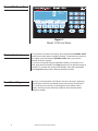
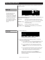
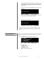
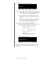
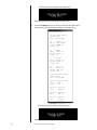
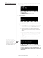
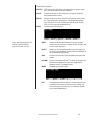
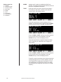
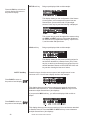
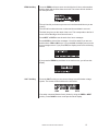
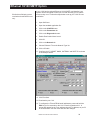
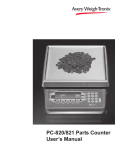
Model 1310 Indicator
User’s Manual
CAUTION
Risk of electrical shock. Do not remove cover. No user serviceable
parts inside. Refer servicing to qualified service personnel.
Weigh-Tronix reserves the right to change
specifications at any time.
06/27/06 1310_U.P65 PN 29802-0017G e1 Printed in USA
2
Model 1310 Indicator User’s Manual
Table of Contents
Table of Contents ..................................................................................... 3
Specifications............................................................................................ 4
Introduction ............................................................................................... 5
About This Manual .......................................................................... 5
Model 1310 Indicator ................................................................................ 5
Model 1310 Front Panel .................................................................. 6
Display Contrast .............................................................................. 6
Front Panel Keys ............................................................................ 6
Hard Keys ............................................................................ 7
Soft Keys .............................................................................. 8
PS2 Keyboard Operation ................................................................ 8
Serial Configuratin .......................................................................... 8
Operating Instructions ............................................................................... 9
ID Soft Key .................................................................................. 9
REPORT Soft Key ........................................................................ 11
EDIT Soft Key ............................................................................... 15
ACCUM Soft Key .......................................................................... 18
1310 Menu/Clearing the Database ............................................... 19
Setting Time and Date ............................................................................ 20
Accessing Software Version ................................................................... 20
Error Messages ....................................................................................... 21
Error Messages for SensorCommTM .............................................. 21
Error Message from the Ghost Feature ........................................ 21
911 Diagnostic Menu .............................................................................. 22
SCOMM Soft Key .......................................................................... 25
Ethernet 10/100 SMTP Option ................................................................ 29
Pages are numbered consecutively beginning with the cover page.
Model 1310 Indicator User’s Manual
3
1310 Specifications
Power Input
Excitation
Operational Keys
Operational Annunciators
Display
Display Characters
Display rate
A to D Conversion Rate
Unit of Measure
Capacity Selections
Incremental Selections
Decimal locations
Displayed Resolution
Audio Output
Time and Date
Internal Resolution
Harmonizer ™ digital filtering
Memory
Universal 85-265 VAC, 50/60Hz, 75VA
10 Volts DC or 10 volts AC square wave capable of driving up to thirty-two 350-ohm weight
sensors. Indicator is also capable of driving Quartzell TM transducers
Zero, Tare, Print, Units, Select, Enter, Escape, Clear, 0-9/Alpha,
Decimal Point and Five Soft Keys labeled per selected operational routine.
Displayed symbols indicate motion, center of zero, unit of measure and more.
Model 1310—Dot graphic display, 5"W x 1.33"H provides images and up to eight lines of
weight and/or text. 240 x 64 dots cold cathode flourescent backlit, white on blue.
Application defined. 1.16" to 0.145" high.
Selectable, from 1 in 10 seconds to 10 times per second
60 times per second
Pounds, kilograms, grams, ounces, pounds and ounces and four programmable custom units
Up to 10,000,000 selectable
Multiples and sub multiples of 1, 2, 5
88888888 pick any location relative to division size
Up to 1 part in 10,000,000
Audio tone for key contact assurance or operational alarms
Battery protected real time clock is standard
1,000,000 counts analog, Quartzell TM transducer higher
Fully programmable to ignore noise and vibration
128K (expandable to 8MB)
Standard input and outputs
Com 1: RS232, RS-485/422, QuartzellTM, SensorCommTM
Com 2: RS232, 20 mA current loop
Com 3: RS232, RS-485/422, QuartzellTM, SensorCommTM
Com 4: RS232, RS-485/422, QuartzellTM, SensorCommTM
(One bi-directional signal per port)
Four set point I/O ports via OPTO 22 I/O modules
1 Analog scale input
PS/2 Keyboard port
Dimensions
7.25" H x 11" W x 8.25" D (184 mm x 279 mm x 205 mm)
Available Options
Fieldbus Network Interfaces
Operating Temperatures
Enclosure
Weight
Agencies
4
- Multiple analog scale inputs, up to seven additional
- Eight fully isolated, programmable analog outputs (selectable 0-20mA, 0-24mA, 4-20mA,
0-5VDC, 0-10VDC, ±5VDC, ±10VDC)
- Remote expanded control interface for TTL or solid state up to 64
- OPTO 22 Generation 4 I/O Modules
- Internal modem
- Memory Expansion - 1, 4, 5, 8 MB (battery backed SRAM)
- PC (AT) style alphanumeric keyboard
- Up to sixteen pulse counter inputs
- SensorCommTM Digital j-box
- TraxleTM total truck and axle weighing
Device Net TM, ProfiBus®, ControlNetTM, InterBus, ModBus Plus, Ethernet 10/100 (ModBus
TCP, TCP/IP (sockets), HTTP, SMTP, FTP, EtherNet/IP)
NTEP 14 to 104° F (-10 to 40° C), 10 to 90% relative humidity
Stainless steel wash down enclosure NEMA 4X
17 lb, 7.7 kg
NTEP Class III/IIIL:10,000d CC# 01-033 A1
FCC Class A
Model 1310 Indicator User’s Manual
Introduction
About This Manual
Configuration file
name is
14835B0A.310
This manual covers the information you need to understand the operation of
your Model 1310 instrument.
Major sections of this manual are headed by titles in a black bar like Introduction above. Subheadings appear in the left column. Instructions and text
appear on the right side of the page. Occasionally notes, tips, and special
instructions appear in the left column.
Model 1310 Indicator
The Model 1310 is a stand alone or network capable weight indicator and
process controller. Built into the Model 1310 are the following standard
features:
Plug the Model 1310 into an
easily accessible grounded
outlet only. Never use the unit
without an appropriate earthground connection.
Any computer based system
should have a separate,
grounded power circuit. We
recommend one for the
Model 1310.
• 4 serial ports
• Time
• Date
• Stainless steel enclosure
• Large graphic display
• Default Multi-Tare Memory and Accumlator application
The Model 1310 front panel is shown in Figure 1. The front panel includes
the following:
• Dot graphic display, 5"W x 1.33"H provides images and up to eight
lines of weight and/or text. 240 x 64 pixel cold cathode flourescent
backlit, white on blue
• Five variable function soft keys (F1-F5)
• Alphanumeric keypad
• SELECT key
• UNITS key
• PRINT key
• TARE key
• ZERO key
• C (Clear) key, Power Off/On
• ESC (Escape) key
• ENTER key
• Decimal point key
Model 1310 Indicator User’s Manual
5
Model 1310 Front Panel
Figure 1
Model 1310 Front Panel
Display Contrast
To increase the contrast of the display, press and hold the DECIMAL POINT
and 7 keys until the desired contrast is reached. To decrease the contrast of
the display, press and hold the DECIMAL POINT and 1 keys until the
desired contrast is reached.
If you have an optional PS2 style keyboard installed, to increase the contrast, press and hold the ALT and Page Up keys until the desired contrast is
reached. To decrease the contrast of the display, press and hold the ALT
and Page Down keys until the desired contrast is reached.
Front Panel Keys
6
The keys on the front panel of the Model 1310 are of two types, hard keys
and soft keys. Hard keys are labeled directly and soft keys are labeled F1F5. If a soft key has a function, its label appears at the bottom the the
display. Soft keys function differently at different times and their labels
change as needed.
Model 1310 Indicator User’s Manual
Below are brief descriptions for each of the hard key functions:
Hard Keys
Use this key to toggle
UPPER and lower case
alpha characters, while
entering alphanumeric
characters. This works
only if Lower Case has
been enabled.
Repeatedly press the SELECT key to scroll through the
available weight reading displays. (Examples - gross,
net, tare, minimum, maximum, etc.)
For alpha entries, this key toggles UPPER/lower case
entry (if Lowercase Enable is turned on in the configuration). If lower case is selected, "abc" will appear in the
upper right of the display.
Press the UNITS key to scroll through the available
units of measure (lb, kg, oz, etc.).
By default the print format #0
sends:
Gross
Tare
Net
They are transmitted from port
one only.
Press the PRINT key to send data to a connected
printer. By default this key performs a DOPRINT
command followed by a DOACCUM command.
Press the TARE key to tare the current gross weight,
then repeatedly press SELECT to scroll through the
tare, gross and net weight displays.
Press the ZERO key to establish a zero reference. A
center-of-zero icon will be displayed when the weight is
within ¼ division of zero. During motion an M will appear
below the center-of-zero icon.
ON/OFF
Clear
key
If the indicator is powered down
via the ON/OFF/Clear key or
by sleep mode time-out, press
this key to power the indicator
back up.
Press the ESCAPE key to back out of menus or cancel
a numeric entry without accepting the value. Press and
hold the ESCAPE key for 3-5 seconds to gain access to
Password Entry Mode.
Press the C(Clear) key to clear values from the display
prompts. Press and hold the C key for five seconds to
power down the indicator.
Press the ENTER key to enter a keyed in value or
accept a displayed choice.
If a display appears in which
alpha or numeric characters
can be entered, key function
switches automatically so
that repeated pressing of
one key causes the number
to appear first followed, by
the alpha characters in
descending order as labeled
on the key. If you wait for the
cursor to appear on the
display and press a key, a
new character is added to
the previous one entered.
The alphanumeric keypad is for entering number and
alpha characters. If a display for entering numbers only
appears, you can key in the numbers using the keypad
normally.
If a display appears in which alpha or numeric characters can be entered, key function switches automatically
so that repeated pressing of one key causes the number to appear first, followed by the alpha characters in
descending order as labeled on the key. If you wait for
the cursor to appear on the display and press a key, a
new character is added to the previous one entered.
Model 1310 Indicator User’s Manual
7
Soft Keys
Soft keys are so called because their function is not fixed. Functionality can
change as mode of operations change or as the program for your particular
setup changes.
There are five soft keys located directly below the display. They are labeled
F1-F5 on the overlay. If the keys are needed during any operation, a
descriptive label appears in the display directly above the active key. There
are only five key labels available at one time but this does not limit the
potential usefulness of these keys. Programs can be created to enable one
key to access another level of operation with five more key names and
functions.
PS2 Keyboard
Operation
If the Caps lock or Num Lock
keys are pressed, the corresponding lights on the keyboard may not light up.
If Lower Case is disabled, the
character shown on the display
will be in upper case no matter
what state the Caps Lock key
is in.
If you have an optional PS2-style keyboard attached to the indicator, below
is a list of keyboard key strokes and their equivalent on the indicator:
Keyboard
Indicator
ALT-S
ALT-Z
ALT-T
ALT-C
ALT-U
ALT-P
ALT-ESC
ENTER
SELECT key
ZERO key
TARE key
C key (clear)
UNITS key
PRINT key
ESCAPE
1..9
A..Z
F1..F5
.
Y
N
ALT + PgUp
ALT + PgDn
Serial Configuration
8
Access to setup menus
ENTER key
or YES soft key
ESC key
or NO soft key
Numeric entry
Alphabet entry
F1..F5 key
Decimal point
YES soft key
NO soft key
Increase contrast
Decrease contrast
Serial port #2 is configured for use with a WP-23X printer. Configuration is
9600 baud, 8 data bits, no parity, and 1 stop bit.
Model 1310 Indicator User’s Manual
Operating Instructions
The Model 1310 provides multiple tare memory, transaction counter and
weight accumulator.
Power Up
The default application has
these optional abilities:
• send an email message after
10 system over or underloads
• web page report generation
You must have the optional
card installed and configured to
take advantage of these
features.
When the indicator is powered up, you will see this screen:
Below are short descriptions of each soft key's function. Following that are in
depth instructions for using them.
ID soft key
Use this key to enter ID numbers and enter or recall
tare weights and tare ID numbers.(Up to 2000 registers)
REPORT soft key
Use this key to view and print accumlated data for
selected ID numbers.
EDIT soft key
Use this to change ID and tare information.
ACCUM+ soft key Press this key or the ENTER key to accumulate the
displayed weight.
ID soft key
1. Press the ID soft key. . .
is displayed, prompting you to enter an ID#.
2. Key in up to 16 alphanumeric characters for the ID. You can enter
alphanumerics in several ways.
A) Use the CHR soft keys to scroll through the alphanumeric list
and move the cursor using the ADV and PREV soft keys.
B) Use the keypad on the 1310, following the directions for
alphanumeric entry in the Front Panel Keys section of this
manual.
C) Use an optional remote keyboard to enter the numbers and
alpha characters. With a remote keyboard attached, only
alpha entries are allowed from the front panel keys.
When you have entered the ID, press the ENTER key.
If the ID# is new, the number is entered into memory and the
following is displayed:
Model 1310 Indicator User’s Manual
9
If you want to assign a tare value to this ID#, press the YES soft
key and go to step 3.
If you do not want a tare for this item, press the NO soft key. The
tare will be disabled for this item and the display will return to the
opening screen.
3. The following is displayed:
Tare ID#s can be up to 16
alphanumeric characters. This
is useful for describing the
particular container. For
example you could have a Tare
ID# of Pallet 1 or Box 4, etc.
4. Key in up to 16 alphanumeric characters to identify this tare. You can
enter alphanumerics in several ways. See note to the left.
A) Use the CHR soft keys to scroll through the alphanumeric list
and move the cursor using the ADV and PREV soft keys.
B) Use the keypad on the 1310, following the directions for
alphanumeric entry in the Front Panel Keys section of this
manual.
C) Use an optional remote keyboard to enter the numbers and
alpha characters. With a remote keyboard attached, only
alpha entries are allowed from the front panel keys.
When you have entered the Tare ID (up to 2,000 registers), press
the ENTER key.
If the Tare ID exists in memory, the tare weight is recalled and the
opening screen returns in net mode with the tare active. Below is
a sample of what the screen may look like:
If the Tare ID# is new, the number is entered into memory and the
following is displayed:
10
Model 1310 Indicator User’s Manual
To use the current weight on the scale as the tare weight, press
the ACTIVE soft key. The tare weight is put into memory, the
weight is tared and the opening screen returns in net mode with
the tare active.
To key in a tare weight, press the KEY soft key and you will see
this display:
Key in the tare weight and press the ENTER key. The opening
screen returns in net mode with the tare active.
The following is then displayed:
Press NO to save the accumulated weight. Press YES to clear the
accumulated weight. Display returns to the screen shown in step 1
above.
REPORT Soft Key
Use this soft key to print reports on individual IDs, all the IDs in memory, all
the tares, or a combination report with all IDs and all tares. Follow these
steps.
1. Press the REPORT soft key. The following is displayed. . .
For ID go to step 2.
For ID'S go to step 3.
For TARE go to step 4
For DBASE go to step 5
EXIT returns to the opening screen.
Model 1310 Indicator User’s Manual
11
2. Press the ID soft key. The following is displayed. . .
Key in the ID# you want. You can enter alphanumerics in several ways.
A) Use the CHR soft keys to scroll through the alphanumeric list
and move the cursor using the ADV and PREV soft keys.
B) Use the keypad on the 1310, following the directions for
alphanumeric entry in the Front Panel Keys section of this
manual.
C) Use an optional remote keyboard to enter the numbers and
alpha characters. With a remote keyboard attached, only
alpha entries are allowed from the front panel keys.
When you have entered the ID#, press the ENTER key. . .
The ID information is recalled from memory, the information is
sent to a connected printer. Below is a sample report:
Time: 10:20
Date: 11-10-2002
ID
:
Tare :
Accum:
Count:
1234567890ABCDEF
Carton 2856
10000 lb
22
The following is then displayed:
Press NO to save the accumulated weight. Press YES to clear the
accumulated weight. Display returns to the screen shown in step 1
above.
12
Model 1310 Indicator User’s Manual
3. Press the ID'S soft key. A report on all the ID's is generated and sent to
the printer. Below is a sample report.
ID Data Base Report
Time: 22:30
Date: 12-07-2002
ID
:
Tare :
Accum:
Count:
Pallet53
Carton 2856
10000 lb
22
ID
:
Tare :
Accum:
Count:
5002
Pallet 12
14523 lb
16
ID
:
Tare :
Accum:
Count:
Truck1
Pallet 12
45123 lb
743
ID
:
Tare :
Accum:
Count:
Bail 44
Twine 78
4572 lb
200
The following will be displayed during printing:
Display returns to the screen shown in step 1 above.
4. Press the TARE soft key. A report on all the tares ID's and associated
tare weights is generated and sent to the printer. Below is a sample
report.
Tare Data Base Report:
Time: 22:30
Date: 12-07-2002
Tare ID: Carton 2856
Tare
: 100 lb
Tare ID: Pallet 12
Tare
: 1200 lb
Tare ID: Pallet 12
Tare
: 750 lb
Tare ID: Twine 78
Tare
: 50 lb
Model 1310 Indicator User’s Manual
13
The following will be displayed during printing:
Display returns to the screen shown in step 1 above.
5. Press the DBASE soft key. A report on both the ID's and tares is
generated and sent to the printer. Below is a sample report.
Data Base Report
ID Data Base Report
Time: 22:30
Date: 12-07-2002
ID
:
Tare :
Accum:
Count:
Pallet53
Carton 2856
10000 lb
22
ID
:
Tare :
Accum:
Count:
5002
Pallet 12
14523 lb
16
ID
:
Tare :
Accum:
Count:
Truck1
Pallet 12
45123 lb
743
ID
:
Tare :
Accum:
Count:
Bail 44
Twine 78
4572 lb
200
Tare Data Base Report:
Time: 22:30
Date: 12-07-2002
Tare ID: Carton 2856
Tare
: 100 lb
Count : 22
Tare ID: Pallet 12
Tare
: 1200 lb
Tare ID: Pallet 12
Tare
: 750 lb
Tare ID: Twine 78
Tare
: 50 lb
The following will be displayed during printing:
Display returns to the screen shown in step 1 above.
14
Model 1310 Indicator User’s Manual
EDIT soft key
Press this key when you want to create new IDs and/or tares, or modify
existing information.
1. Press the EDIT soft key. The following is displayed. . .
For ID go to step 2.
For TARES go to step 6.
Press EXIT to return to the opening screen.
2. Press the ID soft key. . .
is displayed, prompting you to enter an ID#.
3. Key in the ID# for the item. You can enter alphanumerics in several
ways.
A) Use the CHR soft keys to scroll through the alphanumeric list
and move the cursor using the ADV and PREV soft keys.
B) Use the keypad on the 1310, following the directions for
alphanumeric entry in the Front Panel Keys section of this
manual.
C) Use an optional remote keyboard to enter the numbers and
alpha characters. With a remote keyboard attached, only
alpha entries are allowed from the front panel keys.
Press the ENTER key. . .
If the ID# is new, the number is entered into memory and the
following is displayed:
Tare ID#s can be up to 16
alphanumeric characters. This
is useful for describing the
particular container. For
example you could have a Tare
ID# of Pallet 1 or Box 4, etc.
If you want to assign a tare value to this ID#, press the YES soft
key and go to step 4.
If you do not want a tare for this item, press the NO soft key. The
tare will be disabled for this item and the display will return to the
opening screen.
Model 1310 Indicator User’s Manual
15
4. The following is displayed:
5. Key in a tare ID number to identify this tare and press the ENTER key.
See note on step 4.
If the ID exists in memory, the following screen is displayed.
If the ID# is new, the number is entered into memory and the
following is displayed:
To use the current weight on the scale as the tare weight, press
the ACTIVE soft key. The tare weight is put into memory, and the
following screen is displayed.
To key in a tare weight, press the KEY soft key and you will see
this display:
Key in the tare weight and press the ENTER key. The following
screen is displayed.
16
Model 1310 Indicator User’s Manual
6. Having pressed the TARE soft key in step 1, the following screen is
displayed.
7. Key in the Tare ID# and press the ENTER key.
If the Tare ID# exists you will see the display below. Go to step 8.
If the Tare ID# does not exist in memory you will see the display
below. Go to step 9.
8. If you came here from step 7 your display looks like this:
The Tare ID# exists but you can bail out of changing it by pressing
the NO soft key. The display returns to the Edit screen. If you
press YES the following is displayed:
To use the current weight on the scale as the tare weight, press
the ACTIVE soft key. The tare weight is put into memory and the
Edit screen returns.
Model 1310 Indicator User’s Manual
17
To key in a tare weight, press the KEY soft key and you will see
this display:
Key in the tare weight and press the ENTER key. The Edit screen
returns. Go to step 10.
9. If you came here from step 7 your display looks like this:
To use the current weight on the scale as the tare weight, press
the ACTIVE soft key. The tare weight is put into memory and the
Edit screen returns.
To key in a tare weight, press the KEY soft key and you will see
this display:
Key in the tare weight and press the ENTER key. The Edit screen
returns.
10. Repeat steps 1-9 until you are through editing ID and Tare information.
Press the EXIT soft key when you are finished to return to the opening
screen.
ACCUM soft key
Press the ACCUM soft key to increment the transaction counter and add the
displayed weight to the ACCUM total shown on the display.
If the scale is in motion (indicated by an M on the display) when you press
the ACCUM soft key, the system will try to accumulate the weight but if
motion does not cease, the attempt is aborted and the following is displayed:
ACCUMULATION ABORTED DUE TO MOTION. . .
The display will then return to the opening screen.
18
Model 1310 Indicator User’s Manual
1310 Menu / Clearing the
Database
There is a password protected menu you can access to clear the database
of IDs and tares.
To access the menu, press and hold the ESC key for 5 seconds. The
following is displayed:
Key in 1310 and press ENTER. The following is displayed:
Press the ID'S soft key to delete the ID database information.
Press the TARES soft key to delete the tare database information.
Press the ALL soft key to delete both.
In each case the following screen appears:
Press NO to abort the procedure and the screen returns to the Clear
Memory Menu. Press EXIT to return to the opening screen.
Press YES and the display shows Clearing All Databases. Please wait then
returns to the opening screen when complete.
Model 1310 Indicator User’s Manual
19
Setting Time and Date
1. Press and hold the ESCAPE key until the Model 1310 beeps. . .
The display asks for a password and looks like the example
shown below:
2. Key in 111 and press ENTER. . .
A new soft key set appears.
3. Press the CLOCK soft key to access the time and date setting function.
4. The display shows the current hour value. If this is not correct key in a
new value and press ENTER or press ENTER to accept the current
value. . .
The display shows the minutes value.
5. Repeat step 4 for minutes, seconds, year, month and day. (The day of
the week is calculated automatically from the four digit year.)
6. Press the EXIT soft key to return to normal operating mode.
Accessing Software Version
The time may come when you are asked by a service technician for the
software version of your software. There is a series of key strokes which will
bring that number up on the screen. Below are the instructions for accessing
this information.
1. Press and hold the ESCAPE key until the Model 1310 beeps.
2. Key in the number 111 and press ENTER. (If you wait too long to key in
your password, the display returns to normal operation mode.
3. Press the soft key labeled VIEW.
4. Press the soft key labeled VERS. The software version will appear on
the display.
5. Press any key to scroll through all the information available. Soft keys
appear after the last information display.
6. Press ESC then the Exit soft key to return to normal operation mode.
20
Model 1310 Indicator User’s Manual
Error Messages
Error Messages from
the SensorCommTM
If your Model 1310 is connected to a SensorCommTM digital j-box, you may
see the error messages listed in the table below. Also listed is a description
of the error and possible causes. These may help with servicing. Error
messages will appear in the upper right corner of the display window as
shown in the example of error message #8 shown below.
All error messages below which mention components
are referring to components within the SensorComm product.
Error # Error
Description of Error
Possible Cause
1
Communications error
SensorComm not responding
-Cable
-SensorComm hardware failure
-1310 hardware falure
2
Power fault
+Vin, +EXC, or -EXC has fallen out
of tolerance. Voltage ±5%.
-Power supply failure
-Cable
3
A to D overrange
More than +5mV/V has been applied
to the A to D converter
-Cable
-Weight sensor failure
4
A to D underrange
Less than -5mV/V has been applied
to the A to D converter
-Cable
-Weight sensor failure
5
A to D Initialization
failure
A to D converter not responding
-Component failure
-Power supply problems
6
Weight sensor overrange The weight sensor output has
exceeded the configured amount.
7
Weight sensor deadload
shift warning
The output of the weight sensor is
-Gauging problem on the weight
greater than a configurable percent of sensorf
capacity since calibration
-Mechanical issuse with the scale
8
Weight sensor deadload
shift error
The output of the weight sensor has
increased more than a configurable
percent of capacity since calibration
-Gauging problem on the weight
sensor
-Mechanical issuse with the scale
9
Weight sensor stability
The output of 1 or more weight
sensor is not in the same range as
the rest of the scale.
-Mechanical issuse with the scale
-Weight sensor problem
Error Message from
the Ghost Feature
-Abuse of scale
-Weight sensor failure
You may see an error message when the Ghost feature is enabled.
The display at left tells you the
Ghost option is functioning and that
Cell X has failed.
Model 1310 Indicator User’s Manual
21
911 Diagnostic Menu
The 1310 has an emergency help menu with a password of 911 to help you
diagnose problems with components. Following are the instructions you
need to access this menu and explanations of each part of the menu. Figure
2 shows a flow chart of the soft keys in the 911 menu.
Figure 2
Flowchart of soft keys in the Test menu
Hold the ESCAPE key for 5 seconds then key in 911 at the prompt and
press ENTER. The following is displayed:
This manual covers the information needed to use and
understand SensorComm. For
information on the soft keys not
covered in this manual, see the
1310 Service Manual
PN 29803-0016.
22
Model 1310 Indicator User’s Manual
These softkeys appear:
Inputs and outputs have to be
defined in the WT-BASIC
program for them to work.
KEYPAD
This test lets you check each front panel key for proper operation. Follow the instructions on the display.
SCALE
Press this soft key to view weight sensor outputs. Disabled
when SensorComm active.
SERIAL
Use this to test your ports. Select Port #1 through 4 then short
the TX and RX on the selected port. The display will change
from NO LOOP to LOOP indicating the port is good. Jumper
RTS to CTS to test the handshake lines.
MORE
Accesses the following keys:
INPUT
Allows you to Activate/Deactivate any input setpoint
device such as a switch or contact closure remotely and
monitor it with this menu.
OUTPT
Allows you to Activate/Deactivate any output setpoints
to verify correct hardware operation during installation or
for troubleshooting purposes.
DISP
This test continuously cycles the display through a test
pattern.
SCOMM
Present only if SensorCommTM is active. It accesses the
SensorComm diagnostics which are explained the
following section, SCOMM Soft Key.
MORE
Accesses the following keys:
NET
This diagnostic will only appear if a network option card
is installed. Follow the instructions on the display. For
more information reference the 1310 Network Installation Guide PN29806-0013.
Model 1310 Indicator User’s Manual
23
Modem status list:
1 = initialize
2 = set auto answer
3 = set user config
4 = port ready
5 = dialing
6 = error
7 = connected
8 = disconnected
9 = initialize 2
MODM
Appears only if modem is enabled by a SimPoser
program. The display will show Port #, Status (see list at
left), User configuration information.
TRAFF
Press this soft key to see the System Counter Menu.
This shows you the traffic, overload, and underload
counter values. See example below.
If the scale experiences a load exceeding 105% of
capacity, an overload event is logged. Press the OVER
soft key to see the log of overloads. Example below.
Press the PREV or NEXT soft keys to scroll through the
list of overload event times and dates. Press the
CLEAR soft key to clear the displayed event.
If the scale experiences a negative weight exceeding
105% of capacity, an underload event is logged. Example below.
Press the PREV or NEXT soft keys to scroll through the
list of overload event times and dates. Press the
CLEAR soft key to clear the displayed event.
The traffic counter increments when weight exceeds the
configured trigger point (% of scale capacity). (See the
Service Manual for configuration information.) For the
next weightment to increment the counter, the weight
must fall below the configured re-arm point (% of scale
capacity).
24
Model 1310 Indicator User’s Manual
SCOMM Soft Key
Refer to Figure 2 as the soft keys and functions which apply to
SensorComm are explained below.
When you press the SCOMM soft key, the following keys
appear:
INFO Soft Key
INFO
OUTPT
ERR#
VOLT
MORE
See INFO Soft Key section.
See OUTPT Soft Key section.
See ERR# Soft Key section.
See VOLT Soft Key section.
Brings up the following keys:
SIG
DLOAD
G_LOG
See SIG Soft Key section.
See DLOAD Soft Key section.
See G_LOG Soft Key section.
Press this key to view SensorComm and weight sensor
specifications.
VERS soft key
Brings up a display similar to this example:
The displays on the next few
pages are illustrations of
examples, not actual screen
captures.
This display shows you the serial number,
part number and software revision level of
SensorComm #1. Press the NEXT or
PREV soft key to other active SensorComm J-boxes.
Model 1310 Indicator User’s Manual
25
SETUP soft key
Brings up a display similar to this example:
Press the ESC key to back out
of most displays and return to
the previous display.
This display shows you the configuration of the SensorComm system. In this example the system has two
SensorComm j-boxes with a total of eight weight
sensors. Press any key and the following is displayed:
This screen lets you scroll through all the sensors using
the PREV and NEXT soft keys. Information displayed
for each sensor is programmed capacity, output in mV/
V, serial number and span factor.
VALS soft key
Brings up a display similar to this example:
This display shows you the stored cornering values for
each sensor attached to a SensorComm j-box. Press
any key to see the next SensorComm values if there is
another attached. Returns to VERS-SETUP-VALS soft
key set after viewing the last set of values.
OUTPT Soft Key
Press this key to view the current output of each weight sensor in raw
counts or mV/V. You will see a display similar to this example:
Press DONE to return to
the previous level display.
This display shows you the current output in raw counts for each sensor
attached to SensorComm #1. Press the PREV or NEXT soft key to move
between multiple SensorComm j-box displays.
If you press the MV/V soft key, you will see a display similar to this example:
Press DONE to return to
the previous level display.
This display shows you the current output in mV/V for each sensor attached
to SensorComm #1. Press the PREV or NEXT soft key to move between
multiple SensorComm j-box displays.
26
Model 1310 Indicator User’s Manual
ERR# Soft Key
Press the ERR# soft key to see a record of the last 10 error code numbers
and the dates and the times these occurred. The screen will look similar to
the example below:
The top line tells you how many errors are in the list and which one you are
viewing.
The second line shows the error number and time and date it occurred.
The third line gives you the name of the error. This corresponds to the list of
errors in Error Messages from SensorCommTM.
Press NEXT or PREV to see the entire list of error messages.
Press CLEAR to clear all the messages. You will be asked if you are sure
and be shown YES and NO keys. If you press NO, the display returns to the
error message screen. If you press YES, the display returns to the following
screen:
If you press the ERR# key and there are no active errors, you will see this
display:
VOLT Soft Key
Press the VOLT soft key to see current Voltage In and Excitation voltage
reports. The screen will look similar to the one below:
View other connected SensorComm j-boxes by using the PREV or NEXT
soft key. Press DONE to return to the previous level display.
Model 1310 Indicator User’s Manual
27
SIG Soft Key
Press the ESC key to back out
of most displays and return to
the previous display.
DLOAD Soft Key
Press the SIG soft key to see a constantly changing display similar to the
example below:
This screen shows the number of packets of information sent to the SensorComm system and the number received back correctly. This is a measure of
the relative reliability of your communication setup. If the signal strength
shows a lower percentage, chances are the system is experiencing some
kind of line noise and thus, less reliable communication.
Press the DLOAD soft key to view the deadload analysis for each weight
sensor. You will see a display similar to the example below:
This display shows the calibration counts, current raw counts and difference
for sensor #1.
G_LOG Soft Key
Press the G_LOG soft ket to view the log of error messages concerning
ghosted weight sensors. See example below.
Press the appropriate softkey to scroll through the available error messages.
Time and dates of errors are displayed.
X = active error
Y = Number of errors
2 = Cell number that was "ghosted"
28
Model 1310 Indicator User’s Manual
Ethernet 10/100 SMTP Option
Email data will display system
overload and underload counts
only.
If your 1310 has the optional Ethernet 10/100 SMTP card installed, your
system can be configured to send you an email informing you of system
errors as they occur. Follow the steps below to set up your 1310 for autonotification.
1. Open SimPoser.
2. Open the standard application file.
3. Click on the CONFIG button.
4. Click on the Parameters tab.
5. Click on the Diagnostics button.
6. Enable Email under Alarm Levels.
7. Click OK.
8. Click on the Network tab.
9. Choose Ethernet IT from the Network Type list.
10. Click on Enable.
11. Configure the IP, SUBNET MASK, GATEWAY and SMTP IP as shown
in the example below:
12. Click File>Save.
13. Download to your 1310.
14. To configure the TO and FROM email addresses, press and hold the
ESC key for five seconds on the 1310. Enter the password 411. A
prompt will appear for the From address then the To address, as you fill
in the information. Exit the menu and save the changes.
Model 1310 Indicator User’s Manual
29
30
Model 1310 Indicator User’s Manual
Model 1310 Indicator User’s Manual
31
Avery Weigh-Tronix USA
1000 Armstrong Dr.
Fairmont, MN 56031 USA
Telephone: 507-238-4461
Facsimile: 507-238-4195
e-mail: [email protected]
www.wtxweb.com
Avery Weigh-Tronix UK
Foundry Lane
Smethwick, West Midlands
England B66 2LP
Tel: +44 870 90 34343
Fax: +44 121 224 8183
Email: [email protected]
Web site:www.averyweigh-tronix.com
Avery Weigh-Tronix Canada, ULC
217 Brunswick Boulevard
Pointe Claire, QC H9R 4R7 Canada
Telephone: 514-695-0380
Toll free: 800-561-9461
Facsimile: 514-695-6820
www.weigh-tronix.ca
Weigh Bar® is a registered trademark of Weigh-Tronix Inc.