1
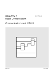
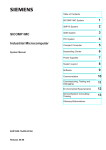
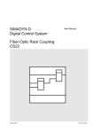
SIMADYN D
Digital Control System
User Manual
Buffer memory module MM3
Edition 05.95
DK-Nr. 251341
User Manual, Buffer memory module MM3
Edition
Edition status
1
Buffer memory module MM3
02.93
2
Buffer memory module MM3
09.94
3
Buffer memory module MM3
05.95
Copying of this document and giving it to others and the use or
communication of the contents thereof is forbidden without express
authority. Offenders are liable to the payment of damages. All rights
are reserved in the event of the grant of a patent or the registration of
a utility model or design.
We have checked the contents of this Manual to ensure that they
coincide with the described hardware and software. However,
deviations cannot be completely ruled-out, so we cannot guarantee
complete conformance. However, the information in this document is
regularly checked and the necessary corrections included in
subsequent editions. We are thankful for any recommendations or
suggestions.
Contents
Contents
Warning information................................ ................................ ................................ ...................... 1
1. Ordering information ................................ ................................ ................................ ................. 3
2. Function description................................ ................................ ................................ .................. 3
2.1. General information ................................ ................................ ................................ ... 3
3. Board design................................ ................................ ................................ ............................. 5
4. Important application information ................................ ................................ .............................. 5
5. Technical data................................ ................................ ................................ .......................... 6
5.1. General information ................................ ................................ ................................ .. 6
5.2. Power supply ................................ ................................ ................................ ............ 6
5.3. Current drain................................ ................................ ................................ ............. 6
6. STRUC mask of the MM3 ................................ ................................ ................................ ........ 6
7. Attachments................................ ................................ ................................ ............................. 7
7.1. Block diagram................................ ................................ ................................ ........... 7
7.2. Layout diagram................................ ................................ ................................ ......... 7
8. ECB instructions................................ ................................ ................................ ........................ 9
Siemens AG Dk-Nr. 251341
SIMADYN D Hardware User Manual
Edition 05.95
Warning information
Edition 05.95
Siemens AG Dk-Nr. 251341
SIMADYN D Hardware User Manual
Warning information
NOTE!
The information in this Manual does not purport to cover all details or variations in equipment, nor to provide
for every possible contingency to be met in connection with installation, operation or maintenance.
Should further information be desired or should particular problems arise which are not covered sufficiently for
the purchaser’s purposes, please contact your local Siemens office.
Further, the contents of this Manual shall not become a part of or modify any prior or existing agreement,
committment or relationship. The sales contract contains the entire obligation of Siemens. The warranty
contained in the contract between the parties is the sole warranty of Siemens. Any statements contained
herein do not create new warranties nor modify the existing warranty.
Warning information
WARNING!
Electrical equipment has components which are at dangerous voltage levels.
If these instructions are not strictly adhered to, severe bodily injury and material
damage can result.
Only appropriately qualified personnel may work on this equipment or in its
vicinity.
This personnel must be completely knowledgeable about all the warnings and
service measures according to this User Manual.
The successful and safe operation of this equipment is dependent on proper
handling, installation, operation and maintenance.
Siemens AG Dk-Nr. 251341
SIMADYN D Hardware User Manual
Edition 05.95
1
Warning information
Definitions
*
QUALIFIED PERSONNEL
*
DANGER
*
WARNING
*
CAUTION
*
NOTE
For the purpose of this User Manual and product labels, a „Qualified person“ is someone who is familiar with the
installation, mounting, start-up and operation of the equipment and the hazards involved. He or she must have
the following qualifications:
1. Trained and authorized to energize, de-energize, clear, ground and tag circuits and equipment in accordance
with established safety procedures.
2. Trained in the proper care and use of protective equipment in accordance with established safety
procedures.
3. Trained in rendering first aid.
For the purpose of this User Manual and product labels, „Danger“ indicates death, severe personal injury and/or
substantial property damage will result if proper precautions are not taken.
For the purpose of this User Manual and product labels, „Warning“ indicates death, severe personal injury or
property damage can result if proper precautions are not taken.
For the purpose of this User Manual and product labels, „Caution“ indicates that minor personal injury or
material damage can result if proper precautions are not taken.
For the purpose of this User Manual, „Note“ indicates information about the product or the respective part of the
User Manual which is essential to highlight.
CAUTION!
This board contains components which can be destroyed by electrostatic
discharge. Prior to touching any electronics board, your body must be electrically
discharged. This can be simply done by touching a conductive, grounded object
immediately beforehand (e.g. bare metal cabinet components, socket protective
conductor contact).
WARNING!
Hazardous voltages are present in this electrical equipment during operation.
Non-observance of the safety instructions can result in severe personal injury or
property damage.
It is especially important that the warning information in all of the relevant
Operating Instructions are strictly observed.
2
Edition 05.95
Siemens AG Dk-Nr. 251341
SIMADYN D Hardware User Manual
Ordering information
1. Ordering information
MM3:
Antenna for inside use:
Antenna for external use:
6DD 1611-0AF0
Hopf Elektronik , Nottebohmstr.41, 58511 Lüdenscheid
FG443610 internal antenna 4436 (Long Distance)
Hopf Elektronik , Nottebohmstr.41, 58511 Lüdenschaid
FG441800 external antenna 4418
2. Function description
2.1. General information
Board MM3 is used in the SIMADYN D system for processor board data transfer and real time
counting. It includes two memory blocks, each 64 kbyte, a 16-bit microprocessor 80C186-8MHz,
which decodes the time signals, the associated peripherals and a 2-kbyte dual port RAM.
Each of the two buffer memory blocks is 64 kbyte, and has a 32 k * 16 organization. One buffer
memory area can be accessed via the L bus, and the other via the C bus. Access is either bytewise or
wordwise. The processor board, which is inserted to the left of the buffer memory board, initializes
and checks both buffer memories. MM3 must be configured so that it is located next to the first
processor module i.e. at slot 3.
The MM3 buffer memory module has no bus termination.
The integrated clock module counts the time, independent of other components, is quartz-clocked,
and buffered from the rack battery, so that the the time is continually updated, even if the subrack is
not operational. The integrated processor ensures that the time in this block is as accurate as
possible. If a time signal is available, this is decoded, and the internal clock is synchronized.
Presently, one of two different time signals is used for synchronization (this is defined in the STRUC
mask when configuring the system).
The first signal is the so-called DCF-77 radio signal, which can be received everywhere in central
Europe. An external antenna is required, as the rooms in which SIMADYN D is used, are generally
screened or accomodate noise emitting equipment. The external antenna must be mounted outside
the room, and oriented towards Frankfurt/Main, where the time signal transmitter is located.
(The direction is specified on the antenna housing). The antenna is connected using BNC socket X7
on the front panel.
The second signal is the audible IRIG-B signal which is transmitted via cable. This signal is especially
used in USA and Canada, but can also be used in other regions when special generators are used. In
this case, high-precision clocks can be used as time transmitter; however, the accuracy can be
somewhat less than for the DCF-77 radio signal. Socket X6 is provided on the front panel for
connecting the IRIG-B signal cable.
The time is indicated on a 7-segment LED displays on the front panel. They are mounted horizontally.
The following is displayed (from the top to the bottom): Date (day of the month and month) and time
(hours, minutes and seconds). A flashing display indicates that the time might be incorrect (e.g. after
switch-on).
The time can also be manually set. Two buttons are used on the front panel. The cursor is moved
with the upper key (identified by a flashing display). A one is added to the value at the cursor position
with the lower key (for seconds, the value is set to zero).
Siemens AG Dk-Nr. 251341
SIMADYN D Hardware User Manual
Edition 05.95
3
Notes
1. For the DCF-77 signal, the time telegram lasts one minute, thus, the display can flash for up to two
minutes even for perfect receptions, until the complete telegram has been received.
2. The standard IRIG-B signal unfortunately does not contain clear information regarding the date, but
only the sequence of the days in the year (no differentiation as far as a leap year is conccerned).
Thus, date information could be incorrect. This is also identified by a flashing display and must be
corrected using the keys.
3. The board is initialized from processor 1. This is realized at run-up in the rack if the MM3 was
configured in the master program. Only then is the buffer memory enabled and the time displayed at
the front panel.
The time is transferred to the dual port RAM (only accessible from the L bus). The time can be readout of the dual port RAM. This is realized by the RTC001 function block. As far as the functional
scope is concerned, this replaces the existing RTC block. For more information, refer to the module
catalog.
LEDs H20-H23 are provided on the front panel. They indicate the status of the time receiver. The
individual LEDs have the following significance:
H20 green
H21 red
H22 green
H23 red
lit
The board is initialized for receiving DF77 signals
dark
The board is initializied for receiving IRIG-B signals
flashes every The time signal is being received
second
lit
Signal has no information - check signal cable !
dark
The time signal does not contain correct information
lit
The information comes minimum of 10 seconds in the
correct format
lit
Error in the time telegram
dark
Decoding running
The MM3 routes the RDYIN signal externally. This line can also be activated from the processor
modules. This is realized by connector X5 on the board. Relay contacts are connected here and thus,
the output is electrically isolated. The relay contacts are closed in the operating status, and are open
for at least 100 ms if a fault condition develops (even with the subrack switched-out). The voltage at
the relay contacts may not exceed 60 V. During switching, the current must not exceed 0.5 A, and the
maximum switching capability is 20 W.
The double test socket for the reset signal (X10/X11) is used to reset the internal processor, and may
not be used during operation.
4
Edition 05.95
Siemens AG Dk-Nr. 251341
SIMADYN D Hardware User Manual
Board design
3. Board design
The MM3 buffer memory board has the following features:
*
Local- and communications bus connection (L- and C bus)
each with 96-pin connector (ES902C) with SIMADYN D control bus assignment
*
64-Kbyte RAM for the local bus
*
64-Kbyte RAM for the communications bus
*
Time buffering using the subrack back-up battery
*
Dual port RAM for transferring time
*
10, 7-segment LED displays for time (H1 to H10).
Format: Day, month, hour, minutes, seconds
*
2 keys for manually setting the clock if a time signal is not used.
*
4 LEDs for status displays (H20 to H23)
*
Relay contacts for the system error signal (X5)
*
1 double test socket for the reset signal (X10 / X11) for resetting the board
4. Important application information
The MM3 buffer memory board may only be used in a SIMADYN D subrack. The subracks must be
equipped with bus terminating modules.
The board must be tightly screwed into the subrack to ensure perfect operation (even during start-up).
If the board is inserted in an adapter for test purposes, the front panel must be connected to the
housing through a short cable.
It is not permissible that the board is either inserted or withdrawn with the subrack power supply
switched-in.
Siemens AG Dk-Nr. 251341
SIMADYN D Hardware User Manual
Edition 05.95
5
Technical data
5. Technical data
5.1. General information
Insulation group
DC
Ambient temperature
Storage temperature
Humidity rating
Altitude rating
Mechanical stressing
A acc. to VDE 0110 § 13, Group 2 at 24 V DC, 15V DC, 5V
0 to +55 degrees C
-40 to +70 degrees C
F acc. to DIN 40050
S acc. to DIN 40040
Installation in stationary equipment which is not necessarily
vibration-free
ES 902 C
233.4 mm * 220 mm
1 slot = 20.14 mm
approx. 700 g
Packaging system
Dimensions
Board width
Weight
5.2. Power supply
Potential
VCC
+15V
VCCR
Rated voltage
+5 V
+15 V
+3.4 V
Minimum
+4.75 V
+14.4 V
+2.2 V
Maximum
+5.25 V
+15.6 V
VCC
5.3. Current drain
Voltage
+15 V
+5 V
+3.4 V
Max. current drain
50 mA
600 mA
0.02 mA
6. STRUC mask of the MM3
: MM3
SIG 1C = 0
TIM 1K <
6
"Radio clock with L/C bus buffer memory"
"Signal type,0=DCF-77,1=IRIG-B,2=..."
"Real-time clock"
Edition 05.95
Siemens AG Dk-Nr. 251341
SIMADYN D Hardware User Manual
Attachments
7. Attachments
7.1. Block diagram
Block diagram, MM3
7.2. Layout diagram
Layout diagram, MM3
Siemens AG Dk-Nr. 251341
SIMADYN D Hardware User Manual
3SE.465 611.9005.00 AO
Edition 05.95
7
Attachments
Block diagram, MM3:
8
Edition 05.95
Siemens AG Dk-Nr. 251341
SIMADYN D Hardware User Manual
ECB instructions
8. ECB instructions
Components which can be destroyed by electrostatic discharge (ECB)
Generally, electronic boards should only be touched when absolutely necessary.
The human body must be electrically discharged before touching an electronic board. This can be
simply done by touching a conductive, grounded object directly beforehand (e.g. bare metal cubicle
components, socket outlet protective conductor contact.
Boards must not come into contact with highly-insulating materials - e.g. plastic foils, insulated
desktops, articles of clothing manufactured from man-made fibers.
Boards must only be placed on conductive surfaces.
When soldering, the soldering iron tip must be grounded.
Boards and components should only be stored and transported in conductive packaging (e.g.
metalized plastic boxes, metal containers).
If the packing material is not conductive, the boards must be wrapped with a conductive packing
material, e.g. conductive foam rubber or household aluminum foil.
The necessary ECB protective measures are clearly shown in the following diagram.
a = Conductive floor surface
b = ECB table
c = ECB shoes
Seated
Siemens AG Dk-Nr. 251341
SIMADYN D Hardware User Manual
d = ECB overall
e = ECB chain
f = Cubicle ground connection
Standing
Edition 05.95
Standing/sitting
9
ECB instructions
10
Edition 05.95
Siemens AG Dk-Nr. 251341
SIMADYN D Hardware User Manual
ECB instructions
Drives and Standard Products
Motors and Drives Systems Group
Postfach 3269, D-91050 Erlangen
Siemens AG Dk-Nr. 251341
SIMADYN D Hardware User Manual
System-Based
Technology
Edition 05.95
11