1
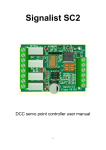
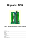
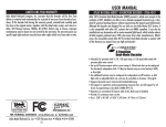
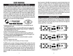
Signalist SC2
DCC servo point controller user manual
1
Contents
Signalist SC2 user manual .................................................................................. 3
Overview......................................................................................................... 3
Connections .................................................................................................... 3
Power connection ........................................................................................ 4
Accessory bus connection ............................................................................ 5
Track connection .......................................................................................... 6
Frog connections.......................................................................................... 7
Servo connections ........................................................................................ 8
Configuration of the SC2 ................................................................................. 9
DCC decoder address configuration ............................................................. 9
Servo endpoint configuration .................................................................... 11
Operation...................................................................................................... 11
List of CVs ..................................................................................................... 12
Specification ................................................................................................. 14
Additional support ........................................................................................ 15
2
Signalist SC2 user manual
Overview
The signalist SC2 provides all the functionality required to operate four points
or crossings which are fitted with standard 3-wire analogue servos. Relays are
provided to switch both polarities of power to the frogs of live frog points and
crossings so no extra external frog switching is required. Standard ‘Y’ cables
can be used when operating two points from a single output on crossovers and
loops. End positions can be set with 13-bit precision allowing very fine
adjustment if your servos are good enough which allows positioning of the
servo to better than a tenth of a degree which can be useful when very small
movements are required.
Configuration of address and servo end positions is by standard programming
of configuration variables on the DCC programming track connection from a
command station or dedicated DCC programmer such as a Sprog. Additionally
the address can be set once installed using the address programming jumper.
The SC2 is equally suited to operation of ordinary RC servos as well as ESU
51804, 51805 and Peco PLS125 servo point motors.
Servos are now the lowest cost method of operating points and using the SC2
in conjunction with servos can offer a considerable saving when compared to
comparable installations using either solenoids or stall motors while offering a
much better solution with the advantages of slow motion, adjustability and
integrated frog switching.
Connections
The following sections show how to connect the SC2 to the points and DCC
system.
3
Power connection
FIGURE 1
Only the DCC track signal is required to control and power the SC2 via terminal
block J1. Normally this will be connected to the accessory bus, but if you do
not have a separate accessory bus it can be connected to the track bus or just
to the track adjacent to the point.
Often the DCC track supply will be insufficient to power high current
accessories so an additional 16V AC or 12-18V DC power supply can be used
instead. This will be essential if your track supply is less than 2A.
When programming the SC1 in service mode, the PWR terminals on J2 will
need to be connected to the programming track output of the command
station as well as the ACC terminals if CV read back or write acknowledgement
is required.
4
Accessory bus connection
FIGURE 2
The DCC track signal is required to control the SC2 via the ACC terminals on
terminal block J1. Normally this will be connected to the accessory bus, but if
you do not have a separate accessory bus it can be connected to the track bus
or just to the track adjacent to the points.
When programming the SC1, the ACC terminals on J1 will need to be
connected to the programming track output of the command station instead of
to the track output.
5
Track connection
FIGURE 3
If use is to be made of the frog switching relays on the SC2 the DCC track signal
must be connected to the SC2 via the Track terminals of terminal block J1.
Normally this will be connected to the track adjacent to the points but can
come from the main track bus. It is best if this supply can be fed via a circuit
breaker so that the command station is not shut down in the event of a short
circuit and the points can still be changed to clear any fault.
On SC2 models which do not have relays fitted the Track terminals will not be
fitted and no connection need be made.
6
Frog connections
FIGURE 4
Frog switching is built in to SC2 models which have the 8-way J2 connector
fitted. Each of the servo outputs has an associated pair of terminals on J2 – FxA
and FxB (where x refers to the output 1-4, output 1 is shown in the diagram).
Where a single point is being switched it will just be necessary to connect the
frog to the FxA terminal but when there are diamond crossings or a second
point associated with a crossover that works together on the same servo
output the FxB terminal can be used as well to power the other frogs as shown
in Figure 4.
It is possible to use an output on the SC2 to switch the polarity of a diamond
crossing without having any servo fitted if required by just connecting the frogs
to the FxA and FxB terminals. This output on the SC2 should then be switched
in conjunction with any routes that are using the crossing.
Should the polarity of the frogs be found to be incorrect after installation the
wires to the FxA and FxB terminals should simply be exchanged.
7
Servo connections
FIGURE 5
Up to four servos can be attached to the standard 0.1” servo pin headers on
the SC2. The first servo is shown connected in Figure 5. The colour coding of
the 3-wire ribbon cables can vary but the normal wiring is for the signal wire to
be white (goes to the ‘W’ terminal), 5V wire to be red (goes to the ‘R’ terminal)
and the 0V wire to be black (goes to the ‘B’ terminal). Check the wiring colours
with your servo supplier if the colours vary from this to ensure the correct
connection. There are four sets of terminals – one set for each servo
numbered 1-4. It is possible for two servos to be connected to a single output
if a servo ‘Y’ cable is used when two points are required to operate together on
a crossover or loop.
When running the servo cables try to ensure that they are well away from high
current solenoid and track feeds if possible to prevent interference from
making the servos twitch. The cables should be loosely twisted on long runs. If
the servo cables need extending use ribbon type extension cables rather than
running individual wires or using multicore cables. Try and mount the SC2 as
close as possible to the servos to minimise any potential problems.
8
Configuration of the SC2
Configuring the SC2 is quite straightforward and in most cases should be as simple as just
setting the DCC address.
DCC decoder address configuration
The SC2 occupies a contiguous block of four (can be up to eight in some configurations)
accessory addresses and can be set to use any accessory address (or extended accessory
address in some configurations). The address is set in CV1 and CV9. The SC2 supports both
decoder address mode and output address mode. The address mode can be changed with
CV29.
Setting the address with decoder address mode (default) when CV29=128
With the default setting of CV29=128 and CV9=0 it is possible to simply set the decoder
address to any address between 1 and 63 by writing the decoder address to CV1. This will
allow the use of accessory addresses 1-252. If accessory addresses are required outside this
range it will be necessary to change CV9 as well.
The values of CV1 and CV9 can be calculated from the following formula:First accessory address = CV9 x 256 + CV1 x 4 – 3
With CV29 set to 128 values of CV1 above 63 are not allowed, and 63 will not work for
configurations that use more than four addresses. CV9 can have values 0-7, values above 7
are not allowed.
See note overleaf about variations in addressing used in some command stations.
Setting the address with output address mode when CV29=192
If you change CV29 from the default to 192 the effect of CV1 will change. With CV9=0 it is
now possible to write a value between 1 and 255 to CV1 which will allow the use of
accessory addresses 1-258. If accessory addresses are required outside this range it will be
necessary to change CV9 as well.
The values of CV1 and CV9 can be calculated from the following formula:First accessory address = CV9 x 256 + CV1
CV9 can have values 0-7, values above 7 are not allowed. With CV29 set to 192 CV1 can
have any value between 1 and 255, but values above 248 will not work for some
configurations.
See note overleaf about variations in addressing used in some command stations.
9
Setting the address automatically
It is possible to set the decoder address automatically using the PGM jumper. To set the
address automatically use the following steps.
1.
2.
3.
4.
Power off the SC1.
Fit the PGM jumper to pins 1 and 2 of J5.
Power on the SC1.
Operate the desired base address on your command station to both Normal and
reverse.
5. Power off the SC1.
6. Remove the PGM jumper.
7. Power on the SC1
The address will now be set in CV1 and CV9 in output address mode with CV29 set to 192.
The decoder will respond to contiguous addresses starting with the one that was operated.
The jumper must be removed for normal operation.
Normal operation
Jumper fitted for programming
Figure 6 – PGM jumper J5 location
Important note: -
Many command stations and some software
applications do not follow the NMRA accessory numbering scheme, so it is important to be
aware that setting the address CVs according to the NMRA formulae used above may not
work and some addresses may not be accessible. Lenz, ESU and ZTC are notable in this
respect and you will need to make allowance. Some systems can only operate a subset of
the accessory range, often limited to addresses below 256 or below 1024 so this may need
to be taken in to account also before choosing addresses. If you are not sure how the
addressing works on your system use the automatic address setting mode with the PGM
jumper.
10
Servo endpoint configuration
The endpoints for the four servo outputs can be configured by adjusting the values in the
following tables. While in most cases it will just be necessary to adjust the MSB value for
each endpoint, extra precision can be gained by adjusting the LSB as well. Accuracies of
better than a tenth of a degree are possible should your servo be that accurate. It is
important to ensure that when setting the endpoint values that they are within the range of
the servo being used. Many servos will only operate over a restricted range and will stall if
set to an invalid value resulting in overheating and possible servo damage.
CV
Default value
Description
64
94
Servo 1 Normal position MSB (course)
65
128
Servo 1 Normal position LSB (fine)
66
180
Servo 1 Thrown position MSB (course)
67
128
Servo 1 Thrown position LSB (fine)
72
94
Servo 2 Normal position MSB (course)
73
128
Servo 2 Normal position LSB (fine)
74
180
Servo 2 Thrown position MSB (course)
75
128
Servo 2 Thrown position LSB (fine)
80
94
Servo 3 Normal position MSB (course)
81
128
Servo 3 Normal position LSB (fine)
82
180
Servo 3 Thrown position MSB (course)
83
128
Servo 3 Thrown position LSB (fine)
88
94
Servo 4 Normal position MSB (course)
89
128
Servo 4 Normal position LSB (fine)
90
180
Servo 4 Thrown position MSB (course)
91
128
Servo 4 Thrown position LSB (fine)
Operation
Operation of the SC2 is much like any other accessory decoder. Just simply
follow your command station’s instructions to operate a turnout.
11
List of CVs
Here is the CV list for the current 0.34 revision of the firmware. This list may
change with future firmware revisions.
Most CVs are listed, but some are of no relevance to operating the SC2 so have
not been discussed in this document. The firmware is common to the current
range of Signalist accessory decoders.
CV
Alt.
CV
Def.
value
Range
Description
Notes
1
513
1
0-255
Lower address bits
0-63 only for decoder address
mode
3
515
0
0-144
Output on time in 10mS
increments
0=constant, 1=10mS, 100=1S,
144=1.44S
4
516
0
0-144
Output on time in 10mS
increments
0=constant, 1=10mS, 100=1S,
144=1.44S
5
517
0
0-144
Output on time in 10mS
increments
0=constant, 1=10mS, 100=1S,
144=1.44S
6
518
0
0-144
Output on time in 10mS
increments
0=constant, 1=10mS, 100=1S,
144=1.44S
7 (rd)
519
9
-
Software release number
Accessory firmware
7 (wr)
519
0
0,1,2,10,11,1
2,20,21,22
LokMaus2
Used for LokMaus2
programming mode
8 (rd)
520
98
-
Manufacturer ID
98 = Harman DCC
8 (wr)
520
-
8
Factory Reset
8= Reset to defaults
9
521
0
0-7
Upper address bits
29
541
128
128,192
Configuration bits
192=output address mode,
128=decoder address mode
33
545
0
0-127
Mode
Bits 0-3 as MERG toggle mode,
bit 6 Roco momentary mode
34
546
8
0,8
ACK pin
Do not change (ack load on pin
11)
35
547
0
0-255
invert
Each of the four pairs of bits
inverts a frog relay when set to
11
12
37
549
0
0-255
Default output state
Do not change (each bit will set
a relay coil to be active at reset)
38
550
31
0-255
Decoder type
31=SC2 with frog relays
48
560
255
0-255
Brightness of output A
Do not change (Relay coil power)
49
561
255
0-255
Brightness of output B
50
562
255
0-255
Brightness of output C
51
563
255
0-255
Brightness of output D
52
564
255
0-255
Brightness of output E
53
565
255
0-255
Brightness of output F
54
566
255
0-255
Brightness of output G
55
567
255
0-255
Brightness of output H
56
568
0
0
Special effect for output A
57
569
0
0
Special effect for output B
58
570
0
0
Special effect for output C
59
571
0
0
Special effect for output D
60
572
0
0
Special effect for output E
61
573
0
0
Special effect for output F
62
574
0
0
Special effect for output G
63
575
0
0
Special effect for output H
64-94
-
?
0-250 (MSB)
Servo endpoint value
65-95
-
128
0-255 (LSB)
13
Do not change
See endpoint table above for
detail
Specification
Maximum power supply voltage
16V AC, 24V DC* or 24V DCC*
Minimum track voltage
12V when powered by the track supply*
7V when powered by an external DC or AC
supply
Servo power supply voltage
5V
Output current
1A** (overload limited) while servos moving
Frog relay current
2A
Current consumption
10mA
Number of servo outputs
4
Pulse width
1.0mS – 2.0mS
Pulse frequency
50Hz
Protocol supported
NMRA basic accessory decoder (turnout)
NMRA extended accessory decoder (signal)
Address modes supported
Decoder address mode
Output address mode
Programming modes supported
Direct bit
Direct byte
Page***
Automatic address (using jumper)
* Good ventilation is required when using DC or track voltage above 18V or at maximum
load to prevent overheating.
** Stalled servos drawing high currents may cause overheating and will be likely to damage
the servo. Make sure that servos are free to move through the whole range required.
*** Page mode is only provided as a fall-back in the event that Direct modes do not work or
your system does not support it. Page mode is not recommended.
14
Additional support
The Signalist SC1 is a very complex product, and therefore not every aspect of its operation
can be covered in this manual. If you need any support on things covered in this manual or
for things that have not been covered interactive support is available on the Signalist web
site where you will find a link to the Signalist support forum:-
http://signalist.co.uk/
15
Signalist SC2 user manual Rev 1
© Paul Harman 2014 all rights reserved
16