1
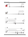
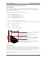
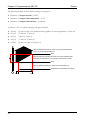
SEC-DC user manual Testing the configuration Chapter 4: Programming the SEC-DC Programming the SEC-DC means telling the control what you want it to do with the equipment and when you want it done. For example, for a single-speed fan set for cooling, you might say “Switch ON when the temperature reaches 80°F.” Before you begin programming your SEC-DC, make sure: The control has power You know which equipment is connected to which stages You have properly connected all equipment to the correct terminals. You have properly configured and tested all equipment connected to the variable and relay stages. For more information, read Chapter 3: Configuring your SEC-DC on page 16. Use Appendix F: Settings worksheets on page 53 when programming your SEC-DC. Understanding how the SEC-DC operates Understanding how the SEC-DC operates can help you configure and program your control more efficiently, and control your environment more effectively. The following is just one example of the configuration for the variable and relay stages. There are seven programs (A to G) you can use or customize to your needs. The configuration and settings for the following example are the factory defaults for program A. 1 Group set point room. Parameter 1 2 3 4 5 6 7 8 9 12 is the target temperature for the 2 Stage 1 idle speed is the speed, in percentage of full power, at which the stage 1 fan operates for minimum ventilation. 3 Stage 1 idle range is the temperature below which the stage 1 fan is off and the inlet is closed. When the temperature is between the idle range and set point, the fan operates at idle speed. 15 16 19 20 21 22 23 30 31 Program A setting Group set point (°F) 85.0 Stage 1 idle speed (%) 20 Stage 1 idle range (°F) 80.0 Stage 1 set point (°F) 85.0 Stage 1 differential (°F) 86.5 Stage 2 idle speed (%) 20 Stage 2 idle range (°F) 87.0 Stage 2 set point (°F) 87.0 Stage 2 differential (°F) 88.5 10 and 11 are not used in the example Stage 5 set point (°F) 84.0 13 and 14 are not used in the example High temperature alarm (°F) 95.0 Low temperature alarm (°F) 80.0 17 and 18 are not relevant in the example Stage 1 configuration COOL Stage 2 configuration COOL Stage 3 configuration VAR1 Stage 4 configuration VAR2 Stage 5 configuration HEAT 24 to 29 are not relevant in the example High temperature enable YES Low temperature enable YES 21