1
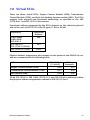
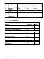
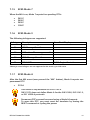
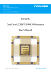
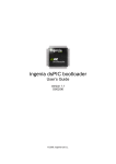
User Guide ECUsim™ 2000 Multiprotocol Software Configurable OBD-II ECU Simulator Information contained in this document is subject to change without notice. Trademarks are property of their respective owners. Copyright © 2013 OBD Solutions. All rights reserved. Printed in the United States of America. Table of Contents 1.0 Overview ................................................................................................................ 4 1.1 General Features .................................................................................................. 5 1.2 Package Contents................................................................................................ 5 2.0 User Interface ....................................................................................................... 6 2.1 Interface Elements .............................................................................................. 6 3.0 Basic Operation .................................................................................................... 8 3.1 Setup ........................................................................................................................ 8 3.2 Using the Simulator ............................................................................................ 8 4.0 UART Communication........................................................................................ 9 4.1 Installing USB Drivers ......................................................................................... 9 4.2 Terminal Setup ..................................................................................................... 9 5.0 Software Configuration ...................................................................................10 5.1 Supported Commands ................................................................................... 10 6.0 Advanced Operation ........................................................................................10 6.1 ISO 9141-2 and ISO 14230-4 (5 Baud Init) ............................................... 10 6.2 ISO 14230-4 (Fast Init)..................................................................................... 11 6.3 SAE J1850 and ISO 15765-4 .......................................................................... 11 6.4 Monitoring OBD Traffic .................................................................................. 11 6.5 Status Messages ................................................................................................ 12 7.0 Virtual ECUs .........................................................................................................13 7.1 Engine Control Module (ECM) ..................................................................... 14 7.1.1 ECM: Mode 1 ................................................................................................ 14 7.1.2 ECM: Mode 2 ................................................................................................ 16 7.1.3 ECM: Mode 3 ................................................................................................ 16 7.1.4 ECM: Mode 4 ................................................................................................ 16 7.1.5 ECM: Mode 7 ................................................................................................ 17 7.1.6 ECM: Mode 9 ................................................................................................ 17 7.1.7 ECM: Mode A ................................................................................................ 17 7.2 Transmission Control Module (TCM) ......................................................... 18 7.2.1 TCM: Mode 1 ................................................................................................ 18 7.2.2 TCM: Mode 3 ................................................................................................ 18 7.2.3 TCM: Mode 4 ................................................................................................ 18 7.2.4 TCM: Mode 7 ................................................................................................ 19 7.3 ABS Control Module (ABS) ............................................................................ 19 7.3.1 ABS: Mode 1.................................................................................................. 19 7.3.2 ABS: Mode 4.................................................................................................. 19 7.3.3 ABS: Mode 7.................................................................................................. 19 8.0 Firmware Updates .............................................................................................20 Appendix A: Specifications .....................................................................................21 Appendix B: Revision History.................................................................................21 Appendix C: Warranty..............................................................................................21 Appendix D: Contact Information.........................................................................21 ECUsim™ 2000 User Guide 3 1.0 Overview ECUsim 2000 is a small, lightweight, entry level benchtop simulator that can be used for testing and development of OBD hardware and software. It supports all legislated OBD protocols, fixed and user adjustable parameter IDs (PIDs), diagnostic trouble codes (DTCs), freeze frames, VIN, and many other SAE J1979 services. The unit has five knobs assigned to common PIDs, a “fault event” button, and indicator lights for power, connection, and MIL (Malfunction Indicator Light). Physical connection to the scan tool is made through a standard SAE J1962 female connector. ECUsim 2000 features a USB connection which can be used to configure the simulator and to monitor OBD traffic. The simulator can be purchased with any combination of “unlocked” OBD protocols, from as few as one to as many as five. Attempting to switch to a protocol that is locked will produce a “PROTOCOL LOCKED” message. 4 ECUsim™ 2000 User Guide 1.1 General Features Support for all1 legislated OBD-II protocols: o SAE J1850 PWM o SAE J1850 VPW o ISO 9141-2 o ISO 14230-4 (KWP2000) o ISO 15765-4 (CAN 250/500 kbps, 11/29 bit) Functional and physical addressing Supports three virtual ECUs: ECM, TCM, and ABS Five knobs assigned to frequently used PIDs: o Coolant Temperature o Engine Speed (RPM) o Vehicle Speed o Oxygen Sensor Voltage o Mass Airflow (MAF) Fixed SAE J1979 modes and PIDs “MIL”, “Link” and “Power” indicators “Fault” button USB connection for simulator configuration and OBD traffic monitoring On-the-fly OBD protocol switching Standard J1962F connector Firmware upgradeable 1.2 Package Contents ECUsim 2000 unit 110/220 VAC to 12 VDC switching power supply US style power cable USB cable 1 While ECUsim 2000 supports all legislated OBD-II protocols, only the unlocked protocols will be available for use. Currently, the protocols are unlocked based on customer selection, prior to shipping. ECUsim™ 2000 User Guide 5 2.0 User Interface ECUsim 2000 can be used as a stand alone simulator, or in conjunction with a PC. It features a number of interface elements, shown in the diagram in the next section. 2.1 Interface Elements 6 ECUsim™ 2000 User Guide 1. 2. 3. 4. 5. 6. 7. 8. 9. Power LED Link LED The function of this LED depends on the protocol in use: a. ISO 9141-2 and ISO 14230-4 protocols: the LED is on while at least one ECU is initialized. The LED dims when an OBD message is received. b. J1850 and CAN protocols: the LED blinks when an OBD message is received. Malfunction Indicator Light Knobs assigned to the five commonly used Mode 1 PIDs. Fault button When pressed, the following happens: a. Set MIL and number of stored DTCs (Mode 1, PID 01) b. Generate pending, stored, and permanent* DTCs c. Generate freeze frame data Configuration DIP switch has two switches that set protocol attributes for ISO 15765-4 (CAN). Switch number 1 is also used to select the init type for ISO 14230-4: a. 29 bit/11 bit. Selects CAN frame ID type. b. 500 kbps/250 kbps. Selects CAN baud rate. c. Fast Init/5 Baud Init. Selects the type of initialization for ISO 14230-4. Diagnostic Link Connector (DLC) USB connector Power jack (12 VDC) *SAE J1979 defines permanent DTCs only for ISO 15765-4 (CAN) Use only the provided power supply to power the simulator. Using a different power supply may cause permanent damage which is not covered under the warranty. ECUsim™ 2000 User Guide 7 3.0 Basic Operation ECUsim 2000 comes with protocols unlocked according to the selection you’ve made when placing the order, and is ready to be used out of the box. 3.1 Setup To set up the simulator, follow these steps: 1. 2. 3. 4. Use the configuration DIP switch to set the desired options. Plug the power supply into an available electric outlet. Plug the 12 volt end of the power supply into the power jack of the simulator. Connect the OBD connector of your OBD tester or OBD interface to the DLC. 3.2 Using the Simulator After the power is first applied, the green Power LED will turn on solid, and the Link and MIL LEDs will turn on and off in sequence. The Link light should be flashing or dimming as the messages are exchanged between the tester and the simulator. To generate a malfunction event, press the Fault button. Use the knobs to adjust the values of the respective PIDs. Use the Configuration DIP switch to configure protocol attributes for ISO 15765-4 and ISO 14230-4 (refer to Section 2.1, Interface Elements, for more information). To display currently selected OBD protocol and for information about switching protocols, see Section 5.0, Software Configuration. 8 ECUsim™ 2000 User Guide 4.0 UART Communication ECUsim 2000 features a USB connection. On a Windows or Linux PC, the drivers create a virtual COM port which allows communication using any suitable serial port terminal (e.g., HyperTerminal). 4.1 Installing USB Drivers To communicate with the ECUsim 2000, make sure it is powered on, and connect it to any available USB port. If the operating system does not find & install the drivers automatically, you can download them from FTDI’s website. FTDI Virtual Com Port Drivers http://www.ftdichip.com/Drivers/VCP.htm 4.2 Terminal Setup Almost any serial port terminal emulator program can be used to communicate with the ECUsim. Some of the popular terminals include the HyperTerminal, RealTerm, and TeraTerm. The default communication settings are: Baud rate: 115200 bps Data bits: 8 Parity: none Stop bits: 1 Turn off local echo ECUsim echoes back what you type, so you may want to turn off local echo in your terminal to avoid “seeing double.” ECUsim™ 2000 User Guide 9 5.0 Software Configuration On startup or reset, the PIM prints the welcome banner that looks similar to this: STS2000 v3.1.5 (C) 2013 OBD Solutions > The PIM is now ready to accept user commands. 5.1 Supported Commands For a list of supported commands, see the ECUsim Programming Manual that can be found on the ECUsim 2000 product page, at: http://ecusim.com/2000 6.0 Advanced Operation This section describes the operation of the simulator in different protocol modes. It assumes that the simulator is connected to a PC running terminal emulation software. 6.1 ISO 9141-2 and ISO 14230-4 (5 Baud Init) After switching to the ISO 9141-2 protocol (or ISO 14230-4 with 5 baud init option) the simulator will print the following status message: <WAITING FOR 5 BAUD INIT> It will not respond to any requests until the bus is initialized. After a successful initialization sequence, the simulator will print: <5 BAUD INIT: OK> At this point, the virtual ECUs will start responding to OBD requests. However, if five seconds pass without a supported request (or a keep-alive message) being received, the ECUs will time out and the simulator will go back to waiting for initialization: 10 ECUsim™ 2000 User Guide <ALL ECUS TIMED OUT> <WAITING FOR 5 BAUD INIT> 6.2 ISO 14230-4 (Fast Init) After switching to the ISO 14230-4 protocol with fast init option, the simulator will print the following status message: <WAITING FOR FAST INIT> It will not respond to any requests until the bus is initialized. After a successful initialization sequence, the simulator will print: <FAST INIT: OK> At this point, the virtual ECUs will start responding to OBD requests. However, if five seconds pass without a supported request (or a keep-alive message) being received, the ECUs will time out and the simulator will go back to waiting for initialization: <ALL ECUS TIMED OUT> <WAITING FOR FAST INIT> 6.3 SAE J1850 and ISO 15765-4 Protocols 1, 2, and 5 do not require initialization. Once the simulator reboots after the set protocol command and prints the configuration summary, it will immediately start listening to, and responding to OBD requests. 6.4 Monitoring OBD Traffic By default, the simulator prints incoming and outgoing OBD messages including the message headers, but without the checkbyte. Here is an example of communication between a tester and the simulator on J1850 PWM: Rx: Tx: Tx: Tx: 616AF1 416B10 416B18 416B28 01 41 41 41 00 00 BE 1B 30 13 00 88 18 00 10 00 00 08 00 10 J1850 VPW, ISO 9141-2, and ISO 14230-4 messages follow the same format: each message has a three byte header followed by data bytes. ISO 15765-4 ECUsim™ 2000 User Guide 11 messages have either 11-bit or 29-bit headers. So a typical 11-bit exchange would appear as follows: Rx: Tx: Tx: Tx: 7DF 7E8 7E9 7EA 01 41 41 41 00 00 BE 1B 30 13 00 88 18 00 10 00 00 08 00 10 Same exchange on 29-bit CAN: Rx: Tx: Tx: Tx: 18DB33F1 18DAF110 18DAF118 18DAF128 01 41 41 41 00 00 BE 1B 30 13 00 88 18 00 10 00 00 08 00 10 Monitoring can be turned off using the MON 0 command to increase the refresh rate. To enable monitoring again, issue MON 1. 6.5 Status Messages <UART TX OVERFLOW> UART transmit buffer overflow detected. <MALFUNCTION EVENT> User pressed the Fault button. <WAITING FOR 5 BAUD INIT> The simulator is waiting for an ISO 9141-2 or ISO 14230-4 5 baud initialization sequence. <WAITING FOR FAST INIT> The simulator is waiting for an ISO 14230-4 fast initialization sequence. <5 BAUD INIT: OK> Detected a successful 5 baud initialization sequence. <FAST INIT: OK> Detected a successful ISO 14230-4 fast initialization sequence. <ALL ECUS TIMED OUT> All virtual ECUs had timed out, because a supported request had not been received within P3MAX (ISO 9141-2 and ISO 14230-4 protocols). 12 ECUsim™ 2000 User Guide 7.0 Virtual ECUs There are three virtual ECUs: Engine Control Module (ECM), Transmission Control Module (TCM), and Anti-lock Braking System module (ABS). The ECUs support both physical and functional addressing, as specified in the SAE J2178, Part 1 and ISO 15765-4 documents. Functional address supported by the ECUs depend on the selected protocol and, in the case of ISO 15765-4, the ID type (11-bit or 29-bit): Protocol(s) J1850 PWM J1850 VPW ISO 9141-2 ISO 14230-4 ISO 15765-4 (29-bit) ISO 15765-4 (11-bit) Functional Address $6A $33 $7DF Physical address assignments also depend on the protocol and CAN ID in use, and are summarized in the following table: ECU Engine Control Module (ECM) Transmission Control Module (TCM) ABS Module (ABS) ISO 15765-4 (11-bit ID) $7E0 $7E1 $7E2 Other Protocols $10 $18 $28 29-bit ISO 15765-4, SAE J1850, ISO 9141-2, and ISO 14230-4 addresses follow the physical address assignments outlined in SAE J2178, Part 1. ECUsim™ 2000 User Guide 13 7.1 Engine Control Module (ECM) The following summarizes modes, PIDs, and Infotypes supported by the PCM. 7.1.1 PID Description Fixed/Variable Hex Value 00 Supported PIDs 01-1F Monitors/DTC Count/MIL Fuel System Status Calculated Load Value Engine Coolant Temperature Short Term Fuel Trim: Bank 1 Long Term Fuel Trim: Bank 1 Engine RPM fixed BE1B3013 fixed2 0007EF80 fixed 0201 fixed 32 See PID 01 Monitors table Closed Loop/ Open Loop 20% variable, knob #1 00 to FF -40°C to +215°C fixed 3C -53.1% fixed 46 -45.3% variable, knob #2 Vehicle Speed Sensor Intake Air Temperature Mass Air Flow variable, knob #3 0000 to FFFF 00 to FF 0.00 to 16383.75 rpm 0 to 255 km/h fixed 41 25°C variable, knob #4 Location of Oxygen Sensors Oxygen Sensor Voltage Short Term Fuel Trim OBD Type Time Since Engine Start Supported PIDs 21-3F fixed 0000 to FFFF 01 0.00 to 655.35 g/s Bank 1, Sensor 1 variable, knob #5 00 to FF 0.000 to 1.275 V fixed 80 0% fixed fixed 01 0258 OBD II (CARB) 600 seconds fixed 80022001 01 03 04 05 06 07 0C 0D 0F 10 13 14 14 1C 1F 20 2 ECM: Mode 1 Scan Tool Display When Fault button is pressed, the MIL bit and DTC count bits change. 14 ECUsim™ 2000 User Guide 21 2F 33 40 42 46 Distance Traveled While MIL is Activated Fuel Level Input Barometric Pressure Supported PIDs 41-5F Control Module Voltage Ambient Air Temperature fixed 03E8 1000 km fixed fixed 80 64 50.2% 100 kPa fixed 44000000 fixed 2EE0 12 V fixed 3C 20°C 7.1.1.1 PID 01 Monitors Continuous Monitors Monitor Supported Misfire Yes Fuel System Yes Comprehensive Component (CCM) Yes Compression Ignition Supported No Non-continuous Monitors Monitor Supported Catalyst Yes Heated Catalyst Yes Evaporative System Yes Secondary Air System Yes A/C System Refrigerant No Oxygen Sensor Yes Oxygen Sensor Heater Yes EGR System Yes ECUsim™ 2000 User Guide Ready Yes Yes Yes Ready Yes Yes Yes Yes Yes Yes No 15 7.1.2 ECM: Mode 2 When the user generates a malfunction event, the following freeze frame is stored: PID Description Hex Value 00 02 05 0C 0D Supported PIDs 01-1F DTC that Caused F.F. Storage Engine Coolant Temperature Engine RPM Vehicle Speed Sensor 48180000 0100 8C 4E20 78 7.1.3 Scan Tool Display P0100 100°C 5000 rpm 120 km/h ECM: Mode 3 When the MIL is on, Mode 3 reports six DTCs: 7.1.4 P0100 P0200 P0300 C0300 B0200 U0100 ECM: Mode 4 Issuing Mode 4 request performs the following operations: 16 Turn off MIL (Mode 1, PID 1) Erase Freeze Frame (Mode 2) Erase stored DTCs (Mode 3) Erase pending DTCs (Mode 7) ECUsim™ 2000 User Guide 7.1.5 ECM: Mode 7 When the MIL is on, Mode 7 reports four pending DTCs: 7.1.6 P0107 P0207 P0307 C0307 ECM: Mode 9 The following infotypes are supported: Infotype 00 01 02 03 04 05 06 0A Description Supported Infotypes VIN Message Count* VIN Calibration ID message count* Calibration ID CVN Message Count* CVN ECUNAME Scan Tool Display 1G1JC5444R7252367 JMB*36761500 1791BC82 ECU1-EngineControl *Message count infotypes are not supported in ISO 15765-4, per SAE J1979. 7.1.7 ECM: Mode A After the first MIL event (user pressed the “MIL” button), Mode A reports one permanent DTC: P1234 This mode is only available for ISO15765-4. SAE J1979 does not define Mode A for the SAE J1850, ISO 9141-2, or ISO 14230-4 protocols. Permanent DTCs cannot be erased using a Mode 04 request. To erase this DTC, you must reset the simulator by issuing the RESET command or cycling the power. ECUsim™ 2000 User Guide 17 7.2 Transmission Control Module (TCM) The following summarizes modes, PIDs, and Infotypes supported by the TCM. 7.2.1 TCM: Mode 1 PID Description Fixed/Variable Hex Value 00 Supported PIDs 01-1F Monitors/DTC Count/MIL Engine Coolant Temperature Engine RPM fixed 88180010 fixed* 00000000 variable, knob #1 00 to FF All monitors not supported -40°C to +215°C variable, knob #2 Vehicle Speed Sensor OBD Type variable, knob #3 0000 to FFFF 00 to FF 0.00 to 16383.75 rpm 0 to 255 km/h fixed 01 OBD-II (CARB) 01 05 0C 0D 1C Scan Tool Display *When the Fault button is pressed, the MIL bit gets set, and the DTC count bits change to reflect the number of stored DTCs. 7.2.2 TCM: Mode 3 When MIL is on, Mode 3 reports one DTC: 7.2.3 P0101 TCM: Mode 4 Issuing Mode 4 request performs the following operations on the TCM: 18 Erase stored DTCs (Mode 3) Erase pending DTCs (Mode 7) ECUsim™ 2000 User Guide 7.2.4 TCM: Mode 7 When MIL is on, Mode 7 reports two DTCs: P0102 U1600 7.3 ABS Control Module (ABS) The following summarizes modes, PIDs, and Infotypes supported by the ABS. 7.3.1 ABS: Mode 1 PID Description Fixed/Variable Hex Value 00 Supported PIDs 01-1F Vehicle Speed Sensor OBD Type fixed 00080010 variable, knob #3 00 to FF 0 to 255 km/h fixed 01 OBD-II (CARB) 0D 1C 7.3.2 Scan Tool Display ABS: Mode 4 Issuing Mode 4 request performs the following operations on the ABS: 7.3.3 Erase pending DTCs (Mode 7) ABS: Mode 7 When MIL is on, Mode 7 reports one DTC: B2245 ECUsim™ 2000 User Guide 19 8.0 Firmware Updates The simulator features a bootloader, which allows the user to update the device’s firmware in the field through the USB port. Updates are posted on the ECUsim internet product page as they become available. Once you download the update, follow the steps to update the simulator: 1. 2. 3. 4. Extract the contents of the ZIP file to a folder on your computer. Run StnFirmwareUpdater.exe. Select the COM port associated with the ECUsim. Click the Upload Firmware button to program the simulator with the new firmware. ECUsim Product Page http://www.ecusim.com/2000 20 ECUsim™ 2000 User Guide Appendix A: Specifications Dimensions Weight Power OBD Protocols PC Port Operating Temperature Operating Humidity Storage Temperature Storage Humidity 5.0 x 3.0 x 1.12 in (127 x 76.2 x 28.4 mm) 2.5 oz (70.8 g) 12 VDC @ 2A (max) SAE J1850 PWM SAE J1850 VPW ISO 9141-2 ISO 14230-4 (KWP2000) ISO 15765-4 (CAN 250/500 kbps, 11/29 bit) USB Type B -4° to 131°F (-20° to 55°C) 10 to 85%, non-condensing -40° to 185°F (-40° to 85°C) 5 to 90% non-condensing Appendix B: Revision History Revision B (April 23, 2013) Updated product page links. Edited section 5.1 – removed command description and referenced programming manual. Revision A (November 11, 2010) Initial release of this document. Appendix C: Warranty This product is covered by a one year parts and labor warranty. Appendix D: Contact Information OBD Solutions 1819 W Rose Garden Ln Ste 3 Phoenix, AZ 85027 [email protected] www.obdsol.com ECUsim™ 2000 User Guide 21