1
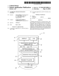
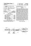
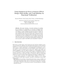
US005 8 17024A
Ulllted States Patent [19]
[11] Patent Number:
Ogle et al.
[45]
[54]
Date of Patent:
Oct. 6, 1998
HAND HELD ULTRASONIC DIAGNOSTIC
5,123,415
6/1992 Daigle .............................. .. 128/661.01
INSTRUMENT WITH DIGITAL
5,295,485
3/1994 Shinomura et a1.
BEAMFORMER
5,360,005
11/1994
5,369,624
11/1994 Fukukita et a1.
Inventors: Botheu;
Greisel, Justin
Seattle;
I‘I Ogle,
coughlin,
Blake W- Seattle;
Larry
Little,
,
,
/
Steven G. Danielson, Seattle; Lauren
_
‘i
. . . . ..
128/6531
....... .. 600/447
ghianglettall.
rieme Ct
e 8.1.
a. ...................
........................
.......................
.. ..
/
_
_
_
_
1979)
Ultra PCI System Speci?cations from Advanced Medical
Products of Columbia, South Carolina (date unknown).
Appl NO _ 863 937
'
128/66007
... ... .... ... ... ...
M1n1v1s0r Service Manual from Organon Teknlka (Sep.
[73] Assignee: SOnOSight, Inc., Bothell, Wash.
[22] Filed:
Wilk
OTHER PUBLICATIONS
S. P?ugrath, Seattle, all of Wash.
[21]
5,817,024
’
“Micros Q.V.” brochure by Advanced Medical Products,
May 27, 1997
Inc. (Sep. 1996).
Related US, Application Data
Primary Examiner—George Manuel
Attorney, Agent, or Firm—W. Brinton Yorks, Jr.
63
[ 1
51
Continuation-in- art of Ser. No. 672,782, Jun. 28, 1996, Pat.
NO. 5,222,412. P
[57]
ABSTRACT
Int. Cl.6 ...................................................... .. A61B 8/00
A hand held ultrasonic instrument is P rovided in a P ortable
[52]
________ __ 600/447
unit Which performs both B mode and Doppler imaging. The
[58]
Field of Search ................................... .. 600/444, 445,
instrument includes a transducer array mounted in a hand‘
600/446, 447, 459; 73/625, 626, 628, 633,
640, 641, 642
held enclosure, With an integrated circuit transceiver con
nected to the elements of the array for the reception of echo
signals. A digital beamformer is located in the hand-held
enclosure for forming ultrasonic scanlines from the echo
signals received by the elements of the array.
[56]
References Cited
U.S. PATENT DOCUMENTS
4,173,007 10/1979 McKeighen et a1. ................... .. 367/11
28 Claims, 15 Drawing Sheets
30
T/R ASIC
/
[><]
FE ASIC
[>q
l>q
D4
40
50
/
/
DSP ASIC
BE ASIC
SYNTHETIC
APERTURE
DAG
ADC
DELAY- SUM
8X
TIME
DATE
SCAN
FREQUENCY
—> CONVERSION
COMPOUNDING
502
TRANSMIT &
COLOR POWER
TIMING CONTROL
ANGIO
GRAPHICS
RISC PROCESSOR
VIDEO
|
l
10
/
|
I
20
3D CPA
MEMORY
MEMORY
/
42
PROGRAM
VIDEO
MEMORY
MEMORY
70
/
32
52
80
\
POWER SUB SYSTEM
BATTERY MANAGEMENT
O O O
USER CONTROL
0
O
E%j
so
54
55
PCMCIA
INTERFACE
LCD
D'SPLAY
U.S. Patent
0a. 6, 1998
Sheet 1 0f 15
cm
.GEF
2
5,817,024
U.S. Patent
0a. 6, 1998
Sheet 2 0f 15
5,817,024
wm
8/
#\mmi.l|
E
U.S. Patent
0a. 6, 1998
Sheet 3 0f 15
5,817,024
.GEw
“HF-NIH
.GEQM
.GEmm.
wm
U.S. Patent
0a. 6, 1998
Sheet 5 0f 15
5,817,024
vwA3mj0m
.5X63z0_m6w
l1\me
U.S. Patent
0a. 6, 1998
500
Sheet 6 0f 15
5,817,024
FIG. 7
r
\
16/8 CHANNEL
BEAMFORMER
\
J
424426
20A
446
20B
20C
20D
20E
20F
20G
20H
U.S. Patent
0a. 6, 1998
F9aIG.
Sheet 9 0f 15
5,817,024
U.S. Patent
Oct.6,1998
0k-
_wmm
“Evmm
.GE2
Sheet 10 0f 15
92_
5,817,024
m1
59%.:
EOE" OmEmt_w<
a
Ntwo+
own
NIEZ<O
U.S. Patent
Oct.6,1998
Sheet 12 0f 15
5,817,024
U.S. Patent
Oct.6,1998
Sheet 13 0f 15
5,817,024
FIG. 13
0
>T|ME
SEGMENT
FIG. 14
WEIGHT
M
181
\
0
'\
180
>SAMPLE
W
183
COUNT
U.S. Patent
.GE
F
m
Oct.6,1998
Sheet 14 0f 15
5,817,024
U.S. Patent
Oct. 6, 1998
Sheet 15 0f 15
5,817,024
FIG. 16
SWITCH FUNCTION
POWER OFF/ON
DESCRIPTION
O
NUMBER OF
CONTACTS
SLIDE SWITCH
1
ACTIvE SCAN/FREEZE O
PUSH AND HOLD FOR ACTIvE SCAN
1
CPA
DOPPLER/CPA FILTER
ANGIO CPA
HIGH/MEDIUM/LOW BUTTON CYCLES
ENABLES AND DISABLES COLOR POWER
1
O
O
THROUGH 3 SELECTIONS
ENABLES 3D CAPTURE WHEN ENGAGED
3D IMAGING MODE
9
BEFORE THE ACTIVE SCAN BUTTON
IS PUSHED
PRINT
@
SENDS SERIAL SIGNAL TO PRINTER
1
1
1
6
CURSOR POSITION IO
OI X/Y POSITION OF CURSOR
4
ENTERS SELECTION
1
_Q_
ENTER
(3
MENU
0
MEASURE
O
FOCUS
O
TOGGLES MENU FUNCTIONS OFF AND
ON, USES CURSOR AND ENTER. FUNCTIONS:
APPLICATION SELECTION USED TO ENTER 1
ALPHA NUMERIC DATA, PATIENT ID,
PATIENT NAME, CINE 2D AND 3D REvIEW
ENABLES MEASUREMENTS, USES
CURSOR AND ENTER
1
ENABLES FOCUS MODE, CURSOR UP
DOWN POSITIONS FOCUS, CURSOR LEFT
RIGHT SELECTS NUMBER OF ZONES
ALLOWS THE USER TO SELECT THROUGH
SEvERAL GRAY SCALE CURVES, SPATIAL
AND TEMPORAL FILTERS WITHIN A
PREDETERMINED SET OF SETUPS FOR
A SELECTED APPLICATION
|MAGE
1
2
DEPTH
@
UP/DOWN, 5 DEPTH SELECTIONS
2
TGC GAIN
®
UP/DOWN
2
BRIGHTNESS
@
LCD DISPLAY CONTROL UP/DOWN
2
CONTRAST
@
LCD DISPLAY CONTROL UP/DOWN
2
5,817,024
1
2
HAND HELD ULTRASONIC DIAGNOSTIC
INSTRUMENT WITH DIGITAL
BEAMFORMER
on a single printed circuit board, eliminating the problems
conventionally posed by connectors and cables. This sophis
ticated ultrasound instrument can be manufactured as a hand
held unit Weighing less than ?ve pounds.
In the draWings:
This is a continuation-in-part of US. patent application
FIG. 1 illustrates in block diagram form the architecture
of a hand-held ultrasound system of the present invention;
Ser. No. 08/672,782, ?led Jun. 28, 1996 now US. Pat. No.
5,722,412.
This invention Was made With government support under
agreement no. N00014-96-2-0002 awarded by the Of?ce of
Naval Research. The government has certain rights in the
invention.
This invention relates to medical ultrasonic diagnostic
systems and, in particular, to a fully integrated hand held
ultrasonic diagnostic instrument.
As is Well knoWn, modern ultrasonic diagnostic systems
are large, complex instruments. Today’s premium ultra
FIGS. 2a and 2b are front and side vieWs of a hand-held
10
FIGS. 3a and 3b are front and side vieWs of the trans
ducer unit of a tWo-unit hand-held ultrasound system of the
present invention;
FIG. 4 illustrates the tWo units of a hand-held ultrasound
15
sound systems, While mounted in carts for portability, con
tinue to Weigh several hundred pounds. In the past, ultra
sound systems such as the ADR 4000 ultrasound system
produced by Advanced Technology Laboratories, Inc.,
20
assignee of the present invention, Were smaller, desktop
units about the siZe of a personal computer. HoWever, such
instruments lacked many of the advanced features of today’s
premium ultrasound systems such as color Doppler imaging
and three dimensional display capabilities. As ultrasound
systems have become more sophisticated they have also
25
become bulkier.
HoWever, With the ever increasing density of digital
electronics, it is noW possible to foresee a time When
ultrasound systems Will be able to be miniaturiZed to a siZe
even smaller than their much earlier ancestors. The physi
cian is accustomed to Working With a hand held ultrasonic
scanhead Which is about the siZe of an electric raZor. It
30
system of the present invention in a tWo-unit package;
FIG. 5 is a schematic diagram of the transmit/receive
ASIC of the ultrasound system of FIG. 1;
FIG. 6 is a block diagram of the front end ASIC of the
ultrasound system of FIG. 1;
FIG. 7 illustrates the aperture control afforded by the
transmit/receive and front end ASICs;
FIG. 8 is a block diagram of the frame and RF header
sequencers of the front end ASIC of FIG. 6;
FIG. 9 is a block diagram of the line, TGC, serial bus and
address sequencers of the front end ASIC of FIG. 6;
FIG. 10 is a block diagram of the summing netWork for
the beamformer channels of the front end ASIC of FIG. 6;
FIG. 11 is a block diagram of one of the dynamic focus
controllers of the front end ASIC of FIG. 6;
FIG. 12 is a block diagram of one of the dynamic Weight
controllers of the front end ASIC of FIG. 6;
FIG. 13 is an exemplary focus control curve used to
explain the dynamic focus controller of FIG. 11;
FIG. 14 is an exemplary Weighting function curve used
Would be desirable, consistent With the familiar scanhead, to
be able to compact the entire ultrasound system into a
scanhead-siZed unit. It Would be further desirable for such an
ultrasound instrument to retain as many of the features of
ultrasound system of the present invention Which is pack
aged as a single unit;
35
to explain the dynamic Weight controller of FIG. 12;
FIG. 15 illustrates a preferred digital delay device for the
beamformer of the present invention; and
today’s sophisticated ultrasound systems as possible, such as
FIG. 16 is a chart of the user controls of the ultrasound
speckle reduction, color Doppler and three dimensional
system of FIG. 1.
Referring ?rst to FIG. 1, the architecture of a hand-held
ultrasound system of the present invention is shoWn. It is
possible to package an entire ultrasound system in a single
imaging capabilities.
40
In accordance With the principles of the present
invention, a diagnostic ultrasound instrument is provided
Which exhibits many of the features of a premium ultrasound
system in a hand held unit. The instrument can be produced
as a single unit or, in a preferred embodiment, the instrument
is a tWo-part unit, one including a transducer, beamformer,
hand-held unit only through judicious selection of functions
45
and features and efficient use of integrated circuit and
ultrasound technology. A transducer array 10 is used for its
solid state, electronic control capabilities, variable aperture,
and image processor and the other including a display and
image performance and reliability. Either a ?at or curved
poWer source for both units. In such a con?guration the
linear array can be used. In a preferred embodiment the array
is a curved array, Which affords a broad sector scanning ?eld.
transducer/processor unit can be manipulated With one hand
While a cable betWeen the tWo units enables the video to be 50 While the preferred embodiment provides suf?cient delay
shoWn on the display unit While the latter unit is held or
capability to both steer and focus a ?at array such as a
positioned for optimal vieWing of the ultrasound image. The
phased array, the geometric curvature of the curved array
reduces the steering delay requirements on the beamformer.
cable also provides energy for the transducer/processor unit
from the display unit.
In a preferred embodiment the ultrasound system, from
the transducer through to a video output, is fabricated on
The elements of the array are connected to a transmit/receive
55
four types of application speci?c integrated circuits
(ASICs): a transmit/receive ASIC Which is connected to the
elements of an array transducer, a front end ASIC Which
performs and controls transmit and receive beamforming
With a plurality of delay channels, a digital signal processing
ASIC Which provides processing of the ultrasound signals
such as ?ltering, and a back end ASIC Which receives
60
ASIC 20 Which drives the transducer elements and receives
echoes received by the elements. The transmit/receive ASIC
30 also controls the active transmit and receive apertures of
the array 10 and the gain of the received echo signals. The
transmit/receive ASIC is preferably located Within inches of
the transducer elements, preferably in the same enclosure,
and just behind the transducer.
Echoes received by the transmit/receive ASIC 20 are
provided to the adjacent front end ASIC 30, Which digitiZes
processed ultrasound signals and produces ultrasound image
and beamforms the echoes from the individual transducer
data. The image can be displayed on either a standard 65 elements into coherent scanline signals. The front end ASIC
monitor or on a liquid crystal display (LCD). Comprised as
it is of ASICs, the electronics of the unit can be fabricated
30 also controls the transmit Waveform timing, aperture and
focusing of the ultrasound beam through control signals
5,817,024
3
4
provided for the transmit/receive ASIC. In the illustrated
acteristics such as the mode (B mode or Doppler), color
Doppler sector or frame rate, and special functions such as
three dimensional display. The user controls also enable
embodiment the front end ASIC 30 provides timing signals
for the other ASICs and time gain control. A poWer and
battery management subsystem 80 monitors and controls the
poWer applied to the transducer array, thereby controlling
the acoustic energy Which is applied to the patient and
minimiZing poWer consumption of the unit. A memory
entry of time, date, and patient data. A four Way control,
shoWn as a cross, operates as a joystick to maneuver cursors
on the screen or select functions from a user menu. Alter
natively a mouse ball or track pad can be used to provide
cursor and other controls in multiple directions. Several
buttons and sWitches of the controls are dedicated for
device 32 is connected to the front end ASIC 30, Which
stores data used by the beamformer.
Beamformed scanline signals are coupled from the front
speci?c functions such as freeZing an image and storing and
replaying an image sequence from the Cineloop memory.
At the bottom of the unit 87 is the aperture 84 of the
end ASIC 30 to the adjacent digital signal processing ASIC
40. The digital signal processing ASIC 40 ?lters the scanline
signals and in the preferred embodiment also provides
several advanced features including synthetic aperture
curved transducer array 10. In use, the transducer aperture is
held against the patient to scan the patient and the ultrasound
formation, frequency compounding, Doppler processing
image is displayed on the LCD display 60.
FIG. 2b is a side vieW of the unit 87, shoWing the depth
such as poWer Doppler (color poWer angio) processing, and
speckle reduction.
of the unit. The unit is approximately 20.3 cm high, 11.4 cm
Wide, and 4.5 cm deep. This unit contains all of the elements
of a fully operational ultrasound system With a curved array
The ultrasound B mode and Doppler information is then
coupled to the adjacent back end ASIC 50 for scan conver
transducer probe, in a single package Weighing less than ?ve
pounds. A major portion of this Weight is attributable to the
battery housed inside the unit.
sion and the production of video output signals. A memory
device 42 is coupled to the back end ASIC 50 to provide
storage used in three dimensional poWer Doppler (3D CPA)
imaging. The back end ASIC also adds alphanumeric infor
mation to the display such as the time, date, and patient
identi?cation. A graphics processor overlays the ultrasound
image With information such as depth and focus markers and
25
cursors. Frames of ultrasonic images are stored in a video
memory 54 coupled to the back end ASIC 50, enabling them
to be recalled and replayed in a live Cineloop® realtime
FIGS. 3 and 4 illustrate a second packaging con?guration
in Which the ultrasound system is housed in tWo separate
sections. A loWer section 81 includes the transducer array,
the electronics through to a video signal output, and the user
controls. This loWer section is shoWn in FIG. 3a, With the
curved transducer array aperture visible at the bottom. The
loWer section is shoWn in the side vieW of FIG. 3b. This
sequence. Video information is available at a video output in
loWer section measures about 11.4 cm high by 9.8 cm Wide
several formats, including NTSC and PAL television for
by 2.5 cm deep. This unit has approximately the same
mats and RGB drive signals for an LCD display 60 or a
Weight as a conventional ultrasound scanhead. This loWer
section is connected to an upper section 83 as shoWn in FIG.
4 by a cable 90. The upper section 83 includes an LCD
video monitor.
The back end ASIC 50 also includes the central processor
for the ultrasound system, a RISC (reduced instruction set
controller) processor 502. The RISC processor is coupled to
the front end and digital signal processing ASICs to control
and synchroniZe the processing and control functions
throughout the hand-held unit. A program memory 52 is
35
display 82 and a battery pack 88. The cable 90 couples video
signals from the loWer unit 81 to the upper unit for display,
and provides poWer for the loWer unit from the battery pack
88. This tWo part unit is advantageous because the user can
maneuver the loWer unit and the transducer 84 over the
patient in the manner of a conventional scanhead, While
coupled to the back end ASIC 50 to store program data
Which is used by the RISC processor to operate and control
the unit. The back end ASIC 50 is also coupled to a data port
holding the upper unit in a convenient stationary position for
vieWing. By locating the battery pack in the upper unit, the
con?gured as an infrared transmitter or a PCMCIA interface
loWer unit is lightened and easily maneuverable over the
56. This interface alloWs other modules and functions to be
attached to or communicate With the hand-held ultrasound
body of the patient.
Other system packaging con?gurations Will be readily
45
apparent. For instance, the front end ASIC 30, the digital
signal processing ASIC 40, and the back end ASIC 50 could
unit. The interface 56 can connect to a modem or commu
nications link to transmit and receive ultrasound information
from remote locations. The interface can accept other data
storage devices to add neW functionality to the unit, such as
an ultrasound information analysis package.
be located in a common enclosure, With the beamformer of
the front end ASIC connectable to different array transduc
ers. This Would enable different transducers to be used With
The RISC processor is also coupled to the user controls
70 of the unit to accept user inputs to direct and control the
the digital beamformer, digital ?lter, and image processor
for different diagnostic imaging procedures. A display could
operations of the hand-held ultrasound system.
be located in the same enclosure as the three ASICS, or the
output of the back end ASIC could be connected to a
PoWer for the hand-held ultrasound system in a preferred
embodiment is provided by a rechargeable battery or an ac.
55
adapter. Battery poWer is conserved and applied to the
components of the unit from the poWer subsystem 80. The
battery pack unit, With the ultrasound ASICs located in the
unit With the transducer array.
Referring noW to FIG. 5, a transmit/receive ASIC 20A is
poWer subsystem 80 includes a DC converter to convert the
loW battery voltage to a higher voltage Which is applied to
the transmit/receive ASIC 20 to drive the elements of the
transducer array 10.
FIGS. 2a and 2b illustrate a one piece unit 87 for housing
the ultrasound system of FIG. 1. The front of the unit is
shoWn in FIG. 2a, including an upper section 83 Which
includes the LCD display 60. The loWer section 81 includes
separate display device. The con?guration of FIG. 4 could
be changed to relocate the user controls onto the display and
shoWn in greater detail. The signal paths of the ASIC 20A
are divided into four identical sections S1, S2, S3, and S4.
In this draWing section S1 is shoWn in internal detail. The
section S1 includes tWo 2:1 transmit multiplexers 408 and
410, each of Which is responsive to a pulser signal on one of
the user controls as indicated at 86. The user controls enable
eight (8) Transmit In lines. Each 2:1 Transmit Multiplexer
has tWo outputs Which drive pulsers 402, 404, and 414, 416,
the user to turn the unit on and off, select operating char
the outputs of Which are coupled to ASIC pins to Which
65
5,817,024
5
6
transducer elements are connected. In the illustrated
operate the transducer array to have a 64 element transmit
embodiment the 2:1 Transmit Multiplexer 408 is coupled to
aperture, represented by transducer element 1—4 . . .
29—36 . . . 61—64 in the draWing. This 64 element aperture
drive either element 1 or element 65, and the 2:1 Transmit
Multiplexer 410 is coupled to drive either element 33 or
element 97. The 2:1 Transmit Multiplexers of the other
sections of the ASIC are each similarly coupled to four
transducer elements. With a separate pulser for each trans
ducer element, the ASIC 20A can independently and simul
is centered betWeen elements 32 and 33. This arrangement
is capable of driving all of the elements of a 64 element
aperture for each transmitted ultrasound Wave. The control
registers of the eight ASICs 20A—20H can be conveniently
coupled to separate lines of an eight line data bus from the
beamformer, each line serving as a serial bus for a particular
taneously drive eight of the sixteen transducer elements to
Which it is connected.
The transducer element pins to Which the pulsers of each
section are coupled are also coupled to the inputs of a 4:1
Receive Multiplexer and SWitch 412. When the pulsers are
10
control register, thereby enabling all eight control registers
to be loaded simultaneously.
Echo signal reception over the full 64 element aperture
can be accomplished in several Ways. One is to employ a
folded and synthetic aperture. After a ?rst Wave transmission
driving the transducer elements during ultrasound
the echoes on elements 17—32 are received and folded
transmission, a signal on a Transmit On line Which is 15 together With the echoes from elements 48—33. That is, one
coupled to all of the 4:1 Receive Multiplexers and SWitches
Sum Bus line Would have the echoes from elements 17 and
on the ASIC sWitches them all into a state Which presents a
48 multiplexed onto it, another Sum Bus line Would have the
high impedance to the high voltage drive pulses, thereby
echoes from elements 18 and 47 multiplexed onto it, and so
insulating the rest of the receive signal paths from these high
voltage pulses. All of the 4:1 Receive Multiplexers and
forth. These sixteen folded signals are appropriately delayed
SWitches of the ASIC are also coupled to a Receive Test pin
of the ASIC, by Which a test signal can be injected into the
signals. After a second Wave transmission the outer elements
and combined by the beamformer to develop a focused
of the aperture are used for folded reception, delayed, and
combined With each other and the ?rst focused signals to
receive signal paths and propagate through the receiver
system. During echo reception each 4: 1 Receive Multiplexer
and SWitch couples the signals of one of the four transducer
elements to Which it is coupled to a 1:16 Multiplexer 418 by
Way of a ?rst TGC stage 416. The gain of the ?rst TGC
stages on the ASIC is controlled by a voltage applied to a
TGC1 pin of the ASIC Which, in a constructed embodiment,
comprises tWo pins for application of a differential control
voltage. The 1:16 Multiplexers of each section of the ASIC
each route received echo signals to one of the sixteen (16)
lines of a Sum Bus 440. TWo of the sixteen Sum Bus lines
are shoWn at the right side of the draWing, and are coupled
to ?lter circuits 222. The ?ltered bus signals are coupled to
complete the aperture.
25
techniques, or by use of a coarse aperture reception
technique, as described in Us. Pat. No. 4,542,653. In this
technique, adjacent elements Which Were independently
excited during beam transmission are paired during recep
tion by combining their received signals and using the same
focusing delay for them. Effectively, this means that the
transducer pitch is coarser during reception by a factor of
35
input pins leading to tWo second TGC stages 424 and 426,
the gain of Which is controlled by the voltage applied to one
tWo. While this Will raise the level of the grating lobes of the
received beam pattern, the combined transmit and receive
beam patterns Will still be acceptable, and the system Will
bene?t by the higher sensitivity of a larger receive aperture.
If the grating lobes should prove objectionable, they can be
reduced by using an aperiodic aperture, in Which the number
or tWo TGC2 pins. The outputs of these second TGC stages
in the illustrated embodiment are connected to output pins
leading to channels of the ultrasound system’s beamformer.
The ASIC 20A also includes a control register 430 Which
receives control signals over a serial bus from the beam
former. The control register distributes control signals to all
of the multiplexers of the ASIC as shoWn by the Ctrl. input
arroWs.
This N:1,1:M ASIC architecture can be used With an
eight channel beamformer 500 in place of the 16 channel
beamformer by use of the folded and synthetic aperture
of elements combined as groups vary from group to group
across the aperture. The aperiodic aperture Will effectively
blend the grating lobe effects into a uniform image back
ground.
45
A constructed embodiment of ASIC 20A Will have a
In one such arrangement the signals received by four
transducer elements are directed to the same Sum Bus line,
number of pins for supply and bias voltages and ground
by suitably programming the 1:16 Multiplexers, for appli
connections and are not shoWn in the draWing.
cation to the inputs of each of eight beamformer channels.
This alloWs the received signals from elements 17 and 18 to
be combined With the received signals from elements 47 and
48 on the same Sum Bus line, and all four signals coupled
to the input of one beamformer channel. Thus, both coarse
receive and folded aperture techniques are employed simul
taneously. A thirty-tWo element aperture can be received
folloWing a single transmitted Wave, or a sixty-four element
A system using the ASICs of the present invention
exhibits an N:1,1:M architecture, Where N is the number of
transducer elements divided by the maximum aperture siZe,
and M is the number of beamformer channels. These ASICs
can be used to connect a Wide variety of transducer arrays of
various numbers of elements to beamformers of different
numbers of channels in numerous Ways. An example of this
versatility is shoWn in the system of FIG. 7, Which shoWs a
55
aperture formed by the synthetic aperture technique With
transducer 10‘ coupled (as indicated by arroWs 506,504) to
eight transmit/receive ASICs 20A—20H, the Sum Bus 440 of
Which is coupled by the sixteen second TGC stages of the
tWo Wave transmissions. If only a ?ne receive aperture is
used, the receive aperture is restricted to thirty-tWo elements
With use of the folded and synthetic aperture techniques, or
sixteen elements With the folded or synthetic aperture tech
ASICs to a sixteen channel beamformer 500. (For clarity of
illustration the second TGC stages are separately illustrated,
although they are in fact integrated on the ASICs.) In this
niques alone.
Thus it is seen that, in the illustrated embodiments, the
transmit/receive ASIC 20A operates With sixteen transducer
elements, and that several of these ASICs can be used With
example the eight transmit/receive ASICs, each having
sixteen pins for connection to transducer elements, are
connected to separately drive all 128 elements of transducer
array 10‘. The 2:1 Transmit Multiplexers of the eight ASICs
are capable of driving 64 elements at once, and thus can
65
transducer arrays of a greater number of elements. Six of
these ASICs can control a 96 element transducer array, for
example.
5,817,024
7
8
A block diagram of the front end ASIC 30 is shown in
FIG. 6. This drawing shoWs one section 30a of the front end
other disabled for each transmitted Wave through the control
signals of the control register 430. This effectively converts
ASIC 30. There are eight such sections on the front end
each pair of 2:1 Transmit Multiplexers to operation as a 4:1
ASIC to provide beamforming of the signals of the eight
Transmit Multiplexer, giving a maximum transmit aperture
Sum Bus lines from the transmit/receive ASIC 20. Each
of thirty-tWo independently controlled elements.
echo signal output is coupled to the input of an A/D
The front end ASIC 30 includes a common control
converter 310, Where the echo signals are converted to
section 330 Which provides overall control for the transmis
sion and receive functions of the eight beamformer channels
on the ASIC. The control section 330 is controlled by and
digital data. The A/D converters are located on the same
integrated circuit as the beamformer itself, Which minimizes
the external connection pins of the integrated circuit. Only
one analog input pin is required for each beamformer
channel, and only one set of digital output pins is required
for the coherently summed output signal. The digital data
10
receives data under control of the RISC processor located on
the back end ASIC 50. The data tables for a particular image
from the A/D converter for each element (or each pair or
group of elements in a folded or coarse aperture) is shifted 15
frame are stored in random access memory (RAM) 32 and
are loaded into the control section 330 under command of
the RISC processor. The control section 330 includes a
number of sequencers for the transmit and receive functions.
into a ?rst in, ?rst out (FIFO) register 312 by a clock signal
A/D CLK. The A/D CLK signal is provided by a dynamic
focus controller 314 Which defers the start of the clock signal
to provide an initial delay, then controls the signal sampling
times to provide dynamic focusing of the received echo
The frame sequencer 332 produces information used by
other sequencers Which identi?es the type of image frame
Which is to be produced. The frame sequencer may, for
signals. The length of the FIFO register 312 is determined by
Doppler scanlines, and that the sequence of scanlines Will be
the transducer center frequency, the aperture siZe, the cur
vature of the array, and the beam steering requirement. A
higher center frequency and a curved array Will reduce the
all odd numbered scanlines folloWed by all even numbered
scanlines. This information is supplied to the line sequencer
steering delay requirement and hence the length of the FIFO
register, for instance. The delayed echo signals from the
example, be loaded With data that de?nes the next frame as
B mode scanlines interspersed betWeen groups of four
25
334, Which controls the timing required to acquire the
desired scanlines. During the scanline acquisition the line
sequencer controls the TGC sequencer 336 so that it Will
FIFO register 312 are coupled to a multiplier 316 Where the
produce the desired sequence of TGC control data. The TGC
echo signals are Weighted by dynamic Weight values pro
vided by a dynamic Weight controller 318. The dynamic
Weight values Weight the echo signals in consideration of the
voltage signal by a digital to analog converter (DAC) 338
and applied to the TGC control input terminal(s) of the
control data from the TGC sequencer is converted to a
effects of the number of active elements, the position of an
element in the aperture, and the desired apodiZation
function, as the aperture expands by the inclusion of addi
transmit/receive ASIC 20. The address sequencer 342 con
trols the loading of data for a neW scanline into various
tional outer elements as echoes are received from increasing
depths along the scanline. The delayed and Weighted echo
35
signals are then summed With appropriately delayed and
Weighted echo signals from other elements and echo signals
from any other delay stages Which are coupled in cascade
realtime registers of the beamformer such as the registers of
the TGC sequencer, the dynamic focus and dynamic Weight
controllers, and the serial bus sequencer 340, Which pro
duces serial data on a serial bus for the control registers of
the transmit/receive ASICs of the system. All registers on the
front end ASIC Which perform real time functions are
double buffered. The registers of the transmit/receive ASIC
through a summer 320. The beamformed echo signals,
together With synchronous over?oW bits, are produced as
are also double buffered so that the control data can be put
output scanline data on an RF data bus. Accompanying each
on the serial bus and loaded into the various registers during
the line preceding the scanline for Which the control data is
used.
sequence of scanline echo signals is identifying information
provided by an RF header sequencer on the ASIC, Which
identi?es the type of scanline data being produced. The RF
The front end ASIC includes in its control section a clock
header can identify the scanline as B mode echo data or 45 generator 350 Which produces a plurality of synchronous
Doppler data, for instance.
ported random access memory can be used to store the
clock signals from Which all operations of the system are
synchroniZed. To prevent interference and crosstalk among
the closely spaced devices of the system, the video output
signal frequency is synchroniZed to a clock signal of the
received digital echo samples, Which are then read out from
the memory at times or sequences Which provide the desired
produce interfering components in the other. Acrystal oscil
Other digital and sampled data storage devices can be
used to provide the beamformer delays, if desired. A dual
clock generator, so harmonics of one frequency Will not
delay for the signals from the transducer elements.
Each section 30a of the front end ASIC includes transmit
control circuits 302—308 for four transducer elements of the
array. The eight sections thus provide transmit control for 32
elements of the array at the same time, thereby determining
the maximum transmit aperture. The transmit control cir
55
and the succeeding draWings, broken lines 9 denote the
cuits produce Waveforms of predetermined durations and
periodicities Which activate the pulsers at the appropriate
times to produce a transmitted acoustic signal Which is
focused at the desired depth of focus. When only a single
front end ASIC With thirty-tWo transmit control circuits is
used With eight transmit/receive ASICS 20A—20H having a
total of sixty-four Transmit In lines, as shoWn in FIG. 7, each
transmit control circuit is coupled to the tWo inputs of each
pair of Transmit Multiplexers 408,410 and one of the
Transmit Multiplexers is programmed to be enabled and the
lator (not shoWn) is coupled to the front end ASIC 30 to
provide a basic high frequency such as 60 MHZ from Which
all of the clock signals of the system may be derived.
FIG. 8 is a block diagram of the frame and RF header
sequencers of the front end ASIC of FIG. 6. In this draWing
boundary of the ASIC, With the circles on the broken lines
indicating terminals (pins) of the ASIC.
Each image frame comprises a group of PRIs, Where
each PRI includes the transmission of an ultrasound Wave
and the reception of echoes from the body in response to the
Wave. Acquisition of an image frame or other sequence such
as spectral Doppler is initiated by the receipt of data and
65
commands from the RISC processor on RISC bus 102. A
number of RAM addresses called “jump addresses” are
stored in jump address register 104. Each jump address is the