1
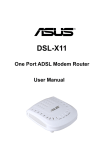
TM
ADSL 200ES/ER
User's Manual
032002-E3-DQT
Contents
Important Safeguards ....................................................................................................... 4
FCC Information ................................................................................................................ 6
Preparing to Install ............................................................................................................ 8
1. Introduction ........................................................................................................................... 8
2. System Requirements ............................................................................................................ 8
3. Front Panel ............................................................................................................................ 9
4. Rear Panel ............................................................................................................................. 9
5. LEDs ................................................................................................................................... 10
Installation ....................................................................................................................... 11
1. Parts Included ...................................................................................................................... 11
2. Connecting the Hardware ................................................................................................... 12
3. Verifying Connections......................................................................................................... 13
4. Question and Answer (Q &A) ............................................................................................ 13
Configuration Settings .................................................................................................... 15
Bridge Configuration...........................................................................................................15
1. Configuring Your PC to Access the 200ES ........................................................................ 15
2. Accessing the 200ES ........................................................................................................... 26
3. System Configuration ......................................................................................................... 27
4. System Status ...................................................................................................................... 32
5. System Administration ........................................................................................................ 35
Router Configuration ..........................................................................................................41
1. Configuring Your PC to Access the 200ER ........................................................................ 41
2. Accessing the 200ER .......................................................................................................... 51
3. Quick Setup ......................................................................................................................... 52
4. System Configuration ......................................................................................................... 56
5. System Status ...................................................................................................................... 71
6. System Administration........................................................................................................ 81
Appendix .......................................................................................................................... 89
Warranty Information ...................................................................................................... 91
INDUSTRY CANADA (IC) NOTICE .................................................................................. 92
Technical Support and Modem Returns ........................................................................ 93
Important Safeguards
Please read and understand all instructions.
Follow all warnings and instructions marked on the product.
Environment
The VisionNet 200ES/ER is intended for in-house stationary use (desktop or wall-mounted).
The maximum ambient temperature may not exceed 40°C (104°F) external to the housing.
The VisionNet 200ES/ER must not be mounted in a location exposed to direct or excessive solar
and/or heat radiation.
The VisionNet 200ES/ER should not be exposed to heat trap conditions and must not be subjected
to water or condensation.
The VisionNet 200ES/ER must be installed in a Pollution Degree 2 environment.
Cleaning
Unplug the 200ES/ER from the wall outlet before cleaning. Do not use liquid cleaners or aerosol
cleaners. Use a damp cloth for cleaning.
Water and Moisture
Do not use the 200ES/ER near water (near a bathtub, wash bowl, kitchen sink, laundry tub, in a wet
basement or near a swimming pool).
Power Sources
The 200ES/ER should be operated only from the type of power source indicated on the marking labels.
If you are not sure of type of power supply to your home, consult technical support or your local power
company.
The main socket outlet must be near the equipment and easily accessible.
The router equipment is not intended to be connected to an IT-type power system.
Power Cord Protection
Do not allow anything to rest on the power cord. Do not locate this product where the cord will be
subject to persons walking on it.
Overloading
Do not overload wall (mains) outlets and extension cords as this can result in fire or electric shock.
4
Servicing
To reduce the risk of electric shock, do not disassemble this product. None of its parts are userreplaceable; therefore, no reason exists to access the interior. Opening or removing the cover may
expose you to dangerous voltages or other risks. In addition, incorrect reassembly can cause electric
shock when the appliance is subsequently used.
If service or repair work is required, take it to qualified service personnel.
Damage Requiring Service
Unplug the product from the wall outlet and refer servicing to qualified service personnel under the
following conditions:
If liquid has been spilled into the product.
If the product has been exposed to rain or water.
If the product does not operate normally when following the operating instructions.
If the product has been dropped and damaged.
If the product exhibits a distinct change in performance.
Modem / Telephone Use
Avoid using a modem/telephone during an electrical storm. There may be a remote risk of electric
shock from lightning.
Do not use the telephone to report a gas leak in the vicinity of the leak.
If telephone service is required on the same line and for optimum ADSL performance, distributed
filters must be installed. Depending on your ADSL configuration and type of filters, installation may
be required by qualified service personnel. Consult your telephone company or ADSL service provider for instructions.
5
FCC Information
Radio Frequency Interference Statement
This equipment has been tested and found to comply with the limits for a Class B digital device,
pursuant to Part 15 of the FCC Rules. These limits are designed to provide reasonable protection
against harmful interference in a residential installation. This equipment generates radio frequency
energy and if not installed and used in accordance with the instructions, may cause harmful interference to radio communications. However, there is no guarantee that interference will not occur in a
particular installation. If this equipment does cause harmful interference to radio or television reception, which can be determined by turning the equipment off and on, the user is encouraged to try to
correct the interference by one or more of the following measures:
*
Reorient or relocate the receiving antenna.
*
Increase the separation between the equipment and receiver.
*
Connect the equipment into an outlet on a circuit different from that to which the receiver is
connected.
*
Consult the dealer or an experienced radio/TV technician for help.
Notice:
Any change or modification not expressly approved by the Guarantee of the equipment authorization
could void the user's authority to operate the equipment.
This device complies with part 15 of the FCC rules. Operation is subject to the following two conditions:
(1) This device may not cause harmful interference and,
(2) This device must accept any interference received, including interference that may cause undesired operation.
The class B digital apparatus meets all requirements of the Canadian Interference - Causing Equipment Regulation.
Cet appareil numerique de la class B respecte toutes les exigences du reglement sur le materiel brouilleur
du Canada.
6
Protection of the telephone network statement
This equipment complies with Part 68 of the FCC Rules. On the solder side (back side) of this equipment is a label that contains, among other information, the FCC Registration Number and Ringer
Equivalence Number (REN) for this equipment. You must, upon request, provide this information to
your telephone company.
This equipment uses RJ11 jacks.
An FCC compliant telephone cord and modular plug are provided with this equipment. This equipment is designed to be connected to the telephone network or premises wiring using a compatible
modular jack, which is part 68 compliant. See installation instructions for details.
The REN is useful to determine the quality of devices you may connect to your telephone line and still
have all those devices ring when your telephone number is called. In most, but not all areas, the sum
of all the REN's of all devices connected to one line should not exceed five (5.0). To be certain of the
number of devices you may connect to your line, as determined by the REN, you should contact your
local telephone company to determine the maximum REN for your calling area.
If your telephone equipment causes harm to the telephone network, the Telephone company may
discontinue your service temporarily. If possible, they will notify you in advance. But if advance
notice is not practical, you will be notified as soon as possible. You will be informed of your right to
file a complaint with the FCC.
Your telephone company may make changes in its facilities, equipment, operations or procedures that
would affect the proper functioning of your equipment. If they do, you will be notified in advance to
give you an opportunity to maintain uninterrupted telephone service.
If you experience trouble with this equipment, please contact the site on the back of this guide for
information on obtaining service or repairs. The Telephone Company may ask that you disconnect
this equipment from the network until the problem has been corrected or until you are sure that the
equipment is not malfunctioning.
No user serviceable parts contain in this equipment.
This equipment may not be used in coin service provided by the telephone company. Connection to
party lines is subject to state tariffs.
7
Preparing to Install
1. Introduction
The VisionNet ADSL 200ES/ER is an integrated ADSL (Asymmetric Digital Subscriber Line)
bridge (ES) or router (ER), which enables high speed Internet access from your Ethernet local area
network (LAN). The 200ES/ER brings high-speed connections to home users, small offices and
telecommuters.
The ADSL 200ES/ER is designed to “plug and play”. Setup of the 200ES/ER is as simple as
connecting it to a PC that is equipped with an Ethernet adapter card and then connecting it to an
ADSL outlet.
2. System Requirements
Does your PC have an acceptable configuration?
Your PC must meet the following minimum requirements:
OS Platform with TCP/IP support
10 or 100 BT Ethernet port
32 Mb RAM or more
8
3. Front Panel
< Front Panel of the VisionNet ADSL 200ES/ER >
4. Rear Panel
Power Switch
LINE Port
DC IN Port
SWAPPER Port
LAN Port
< Rear Panel of the VisionNet ADSL 200ES/ER >
9
5. LEDs
The following table explains the functions of the LEDs located on the Front Panel:
ADSL
Tx/Rx
LAN
Activity
POWER
LEDs
ADSL
Color
Green
Status
Meaning
- Flashing
- Trying to connect ADSL line
- Solid
- ADSL line is linked
Tx/Rx
Green
- Flashing
- Data is transmitted or received to the ADSL line
LAN
Green
- Flashing
- Data is transmitted or received to the LAN side
- Solid
- Ethernet interface is active
Activity
Green
- Flashing
- The device ready to work
POWER
Red
- Solid
- Input power is applied
- Off
- Power Off
10
Installation
1. Parts Included
Check for the following contents of your package.
1. VisionNet 200ES/ER
2. Power Adapter
3. RJ-45 Ethernet Cable
4. RJ-11 Phone Cable
5. CD ROM (Manual)
6. Quick Start Guide
7. External In-line Filter (sold separately)
8. Wall-mount Filter (sold separately)
9. Two-way Adaptor (sold separately)
Note: External in-line and wall mount filters and two-way adaptor are sold separately. If
you did not order a kit, your package will not contain filters.
1
2
3
4
6
7
8
9
5
If you are missing any of the above items, please contact the sales office where you purchased your
unit or your ADSL service provider.
11
2. Connecting the Hardware
SWAPPER Port
LAN Port
DC IN Port
LINE Port
C
B
A
Electrical
Power Outlet
Adaptor Cord
ADSL Service
Port on Wall
RJ-11 Cable
RJ-45 Cable
< Connect the Hardware >
A. Connect one end of the RJ-11 telephone cable to the VisionNet 200ES/ER’s LINE port and the
other end to the ADSL service port (wall jack).
B. Connect the RJ-45 Ethernet cable to the LAN port of the VisionNet 200ES/ER and the other end
to the PC’s Ethernet port.
C. Plug the coaxial jack from the electric power supply adapter into the VisionNet 200ES/ER’s DC
IN port and the other end to the main outlet. Turn on the power switch.
12
3. Verifying Connections
a. If the POWER LED on the VisionNet 200ES/ER is not solid RED...
Verify that the power adapter is plugged securely into the electric outlet.
Verify that the power switch is placed in the “On” position.
b. If the LAN LED on the VisionNet 200ES/ER is not solid GREEN…
Verify that the RJ-45 connection is secure on both the PC Ethernet port and RJ-45 port
on the VisionNet 200ES/ER.
c. If the ADSL LED on the VisionNet 200ES/ER is not solid GREEN within 2 minutes…
Check the RJ-11 connection on the LINE port of the VisionNet 200ES/ER. Make sure
that the RJ-11 is securely connected to the LINE port on the VisionNet 200ES/ER from
the ADSL wall jack.
Note:
If the ADSL does not become solid within 2 minutes and you have verified a
secure RJ-11 connection on the LINE port and wall jack, reconnect the ADSL
line to the SWAPPER port.
4. Question and Answer (Q &A)
Q1: Why do I need a filter on the telephone line attached to the ADSL service?
A1: Converting your regular phone into a Digital Subscriber Line (DSL) can cause audible noises
(high pitched tones and static) when you try to
talk on the phone without a filter. You will need
to install a filter on each telephone or device that
shares the DSL line to eliminate this noise;
phones or devices that share the same telephone
number as your ADSL service. Other devices
where a filter should be placed include answering machines and fax machines. The filters will
enable both Internet access and normal phone
use at the same time.
Q2: How do I connect the filter?
A2: Place the filter in jacks that share the same telephone number with the activated ADSL line.
Q3: When is a two-way adapter required?
A3: If your 200ES/ER shares a jack with another telephone, you will need to install a two-way
adapter. A two-way adapter is not a filter; it merely allows two lines to connect into one jack.
Plug the two-way adapter into the wall jack, plug a in-line filter into one of the two jacks on the
13
two-way adaptor, then connect your telephone to the filter. The remaining jack on the two-way
adaptor is used to connect the 200ES/ER to your ADSL service (a filter should not be used when
connecting to your modem).
Q4: When do I need to use the SWAPPER port?
A4: The LINE port and SWAPPER port cannot be used at the same time. If the ADSL LED does
not become solid in 2 minutes, unplug the RJ-11 from the LINE port and reconnect it to the
SWAPPER port. In most cases, the LINE jack is utilized in typical ADSL connections. In
some areas, this may not be the case, so DQ Technology provides an alternative pin configuration (the SWAPPER port) in case the standard was changed at some point in your wall jack.
SWAPPER Port
LAN Port
DC IN Port
LINE Port
Electrical
Power Outlet
RJ-11 Cable
Two-Way
Adapter
Adaptor Cord
Filter
ADSL Service
Port on Wall
RJ-11 Cable
RJ-45 Cable
Q5: When do I need to use the “RESET” button?
A5: If the VisionNet 200ES/ER cannot be accessed
or an issue cannot be resolved, press the “RESET” button with a pen (press down and hold a
few seconds) to reset the device to factory default settings. Note that all the previous settings
of 200ES/ER will be cleared when you press the
“RESET” button, so you need to re-configure
the 200ES/ER after resetting.
RESET button
14
Configuration Settings
If your service provider has configured your 200ES/ER for the service, do not change these settings
unless instructed by your service provider.
All configuration and management for the 200ES/ER is done via a Web browser. You can change the
200ES/ER settings with a web browser such as Microsoft Internet Explorer or Netscape Navigator.
The 200ES/ER can operate as a bridge or Internet Protocol (IP) router, depending on the type you
purchased. As a result, the 200ES/ER’s configuration is divided into Bridge (ES) and Router (ER)
configuration. Only one of these will apply to your modem.
Bridge Configuration
If you purchased a 200ES bridge modem, please refer to this section.
If you need to change a modem setting, you will need to configure your PC as defined in the following
pages. However, you will need to reconfigure your PC after you are finished with the modem.
Note: If you wish to upgrade your 200ES bridge modem to a 200ER router, please contact
your ISP or DQ Technology.
1. Configuring Your PC to Access the 200ES
To access the configuration pages you must set your PC’s IP address to 10.0.0.1 and Subnet mask to
255.0.0.0. The default address of the modem is 10.0.0.2.
15
Win 95 / Win 98 / Win 98SE / Win Me
Control Panel, then double click on
a. From the Start menu on the tool bar, select Settings
the Network icon.
b. The Network window appears. Select the Configuration tab, scroll to the installed network
component window and select TCP/IP-->NIC (Network Interface Card). Click the
Properties button.
16
c. The TCP/IP Properties window will appear. Select the Specify an IP Address option,
then enter the IP Address as 10.0.0.1 and Subnet Mask as 255.0.0.0.
d. You will be asked to restart your computer to complete the settings. Click Yes to restart
your computer.
17
Win 2000
Control Panel, then double click on
a. From the Start menu on the tool bar, select Settings
the Network and Dial-up Connections icon.
b. The Network and Dial-up Connections window appears. Double click on the Local Area
Connection icon for TCP/IP network adapter.
c. The Local Area Connection Status window appears. Click the Properties button.
18
d. The Local Area Connection Properties window appears. Select Internet Protocol (TCP/
IP), then click the Properties button.
19
e. The Internet Protocol (TCP/IP) Properties window will appear. Enter the IP Address
as 10.0.0.1 and Subnet Mask as 255.0.0.0, then click on the OK button and complete the
settings.
20
Win NT4.0
Control Panel, then double click on
a. From the Start menu on the tool bar, select Settings
the Network icon.
b. The Network window appears. Select the Protocols tab, scroll the network protocols
window and select TCP/IP Protocol. Click the Properties button.
21
c. The Microsoft TCP/IP Properties window appears. Select the IP Address tab and then choose the
Specify an IP Address option. Enter the IP Address as 10.0.0.1 and Subnet Mask as 255.0.0.0,
then click the OK button and complete the settings.
22
Win XP
a. From the Start menu on the tool bar, select Control Panel, then double-click on the
Network Connections icon.
b. The Network Connections window appears. Right-click on the Local Area Connection
for TCP/IP network adapter and select Properties.
23
c. The Local Area Connection Properties window appears. Click on Internet Protocol
(TCP/IP), then click on Properties.
24
d. The Internet Protocol (TCP/IP) Properties window will appear. Select the Use the
following IP address option and enter the IP address as 10.0.0.1 and Subnet mask as
255.0.0.0. Click the OK button and complete the settings.
25
2. Accessing the 200ES
You can use your PC’s web browser to access the web configuration pages in the 200ES. The default
address of the 200ES is 10.0.0.2.
Follow these instructions to open a connection to the 200ES.
A. Start your web browser and enter the web address as 10.0.0.2 on the browser’s address field.
10.0.0.2 is the factory default for the 200ES LAN IP address. If you change the IP address, you
must enter that new IP address in the browser’s address field.
B. When the Enter Network Password window appears, type user name and password to access the
main page of the 200ES. The ADSL 200ES provides two levels of access: User and Administration.
For User level access, the Username is “user” and Password is “password”. If you choose User
login, you can only view settings.
For Administration level access, the Username is “admin” and “Password” is “visionnet”. If
you choose Administrator login, you have full access to the 200ES.
C. The Main Page is shown first when you use a web browser to access the 200ES. The left side of
the page contains 3 menu items: Configuration, Status and Maintenance.
26
3. System Configuration
The Configuration section is used to set up your 200ES to access the Internet.
LAN Page
a. Click the LAN option in the Configuration menu and you will see the following screen.
b. The factory default is set as shown on screen.
c. If you want to customize the setting for the Ethernet interface on the 200ES, enter or change
the following information in the LAN windows.
d. When Setting are completed, click Submit. You can click Reset to bring back the last
setting; this function can only be used before you click Submit.
27
Note1 : Both the IP Address for the Ethernet interface on your200ES and IP Address for
the LAN card on your PC must be on the same Subnet. If you re-configure the
IP Address for the Ethernet Interface on your 200ES, you also need to check or
re-configure your PC’s LAN IP Address as the same Subnet to access the 200ES.
Note2 : In bridge mode, the 10.0.0.2 IP address is only used to access the 200ES’s user
interface. It is highly recommended that you do not change the IP address. If
you choose to change this field, you should configure the IP address to be in a
private address (i.e. 10.x.x, 172.16.x.x or 192.168.x.x).
Definitions
IP Address:
The IP address of the 200ES on the network connected to its LAN interface.
Subnet Mask:
The range of Subnet mask in use for the LAN connected to the Ethernet port. Default is
255.0.0.0.
28
WAN Page
a. Click the WAN option in the Configuration menu and you will see the following screen.
b. In the ENCAPSULATION bar, you can use the drop-down menu to select the encapsulation
method supplied by your ISP. 1483 Bridged IP LLC is the most common and is the default
configuration.
c. Enter the VPI and VCI (0,35 is most common) provided by your ISP. Please confirm with
your ADSL service provider.
d. The ADSL connects and communicates with the WAN interface (Internet) via ATM. In the
ATM structure, the ADSL circuit has a VC (Virtual Circuit). You can set up one or several
Virtual Interfaces to make a connection, communicate individually or simultaneously.
You can configure ATM settings for each virtual circuit which does not affect other virtual
circuits. The screen that appears depends on the operation mode you selected.
29
In the ATM Interface bar, you can set eight ATM VC’s. Choose Yes to enable your VC
settings.
The default is set to 0. Do not set 1~7 unless instructed by your ISP.
e. In the Modulation bar, you can use the pull-down menu to select the modulation protocol.
The factory default is set to Autosense-G.dmt first.
f. When Settings are completed, click Submit. You can click Reset to bring back the last
setting; this function can only be used before you click Submit.
Definitions
VPI:
Enter the number of the Virtual Path Identifier in the VPI field.
VCI:
Enter the number of the Virtual Circuit Identifier in the VCI field.
30
Save Setting Page
Click the Save Setting option in the Configuration menu and you will see the following screen.
Click Submit to save settings.
31
4. System Status
This Section allows you determine if there are any issues with the 200ES.
ADSL Page
a. Click the ADSL option in the Status menu and you will see the following screen.
32
b. You can view the line rate (Data Rate) on your screen after the ADSL link is established.
c. Click the ADSL option in Status each time you want to see the most updated line rate or
ADSL connection status when the ADSL link is established.
Definitions
SNR Margin:
Amount of increased noise (dB loss in SNR) that can be tolerated while maintaining a BER of
10-7.
Line Attenuation:
Measured in dB.
Error Seconds:
The time of a received Reed Solomon codeword for data stream indicating that errors have
been corrected in that codeword.
Loss of Signal:
The received pilot tone power, averaged over 100 ms, is 6dB or more below the reference
power.
Loss of Frame:
When the unit receives two consecutive synchronization symbols, the number of tones with a
mismatch between the expected and the measured bit pattern is lower than the threshold.
CRC Errors:
When a received CRC-8 code for the data stream is not identical to the corresponding generated code at a rate of at most 1 per super frame (17ms).
Data Rate:
When the router is up, these parameters indicate the actual ATM bit rate (without overheat) for
the up stream / down stream paths.
33
Diagnostic Page
Click the Diagnostic option in the Status menu to see the status of Diagnostic tests. Note that in
bridge mode, several tests may fail. This is normal, but you should verify diagnostics results with
your ISP if your connection fails.
34
5. System Administration
The system administration level allows you to change the password and verify/load software revision
levels.
Password Page
a. Click the Password option in the Maintenance menu and you will see the following screen.
b. You can change your User or Admin Passwords in this page.
c. When you have completed your Setting, click Submit. You can click Reset to bring back
the last setting; this function can only be used before you click Submit.
35
Firmware Version Page
Click the Firmware Version option in the Maintenance menu to see the software version of your
200ES.
36
Local Update Page
a. Click the Local Update option in the Maintenance menu and you will see the following
screen. You can upgrade the 200ES’s software from this page.
b. A current version of the 200ES software package must reside either on your hard disk or
on a floppy disk to load onto the 200ES. Click the Browse button next to the passive
software version and locate the new software package on either your hard disk or floppy.
c. Select the correct package and click the Upload button. The software package will be
transferred from your PC to the 200ES.
d. After the update is complete, either power reset your modem or click on the Reboot button.
37
System Log Page
Click on the System Log option in the Maintenance menu and you will see the following screen.
These messages can be saved and sent to your ISP for further analysis if problems occur.
38
Reset to Default Page
a. Click the Reset to Default option in the Maintenance menu and you will see the following
screen.
b. You can reset the device to factory default from this page. Note that all the previous settings
of the 200ES will be deleted when you execute the reset function. You may need to reconfigure the 200ES (if needed).
c. Click Reset and the 200ES will reset settings to factory default and reboot.
39
Help Page
Click the Help option in the Maintenance menu and you will see the following screen.
If you have question or need help, you may refer to the Help pages.
40
Router Configuration
If you purchased a 200ER Router modem, please refer to this section.
In router mode, the 200ER default configuration enables the Dynamic Host Configuration Protocol
(DHCP) server. The DHCP server is a network protocol that enables the 200ER to automatically
assign an IP address to individual computers attached to your 200ER LAN interface.
The following describes how to access your 200ER by setting your PC as a DHCP client. You may
also access your 200ER by statically assigning an IP address to your PC. If you choose this method,
the IP address configured in your PC must be in the same subnetwork as the 200ER.
1. Configuring Your PC to Access the 200ER
If your PC has DHCP client enabled, simply power on your 200ER before starting your PC. The
Ethernet adapter will be assigned an IP address from the DHCP sever. You may also use Window
programs winipcfg.exe or ipconfig.exe to release the old address and renew to request a new address.
If you want to turn on a computer with a DHCP client, configure your LAN IP address to obtain an IP
address automatically. The following steps describe how to configure a Windows based device to
obtain an IP address automatically. (Please consult your OS user’s manual if you have a non-Windows
based device).
41
Win 95 / Win 98 / Win 98SE / Win Me
a. Right-click the Network Neighborhood icon and select Properties.
b. When the Network window appears, select the Configuration tab, then select TCP/IP-->NIC
(Network Interface Card). Click the Properties button.
42
c. The TCP/IP Properties window will appear. Select the IP Address tab. Select Obtain
an IP address automatically, then click OK.
d. You will be asked to restart your computer to complete the settings. Click Yes to restart
your computer.
Win 2000
a. Right-click the Network Neighborhood icon and select Properties.
b. The Network and Dial-up Connections window appears. Double click on the Local Area
Connection icon for TCP/IP network adapter.
c. The Local Area Connection Status window appears. Click the Properties button.
43
d. The Local Area Connection Properties window appears. Select Internet Protocol (TCP/
IP), then click the Properties button.
44
e. The Internet Protocol (TCP/IP) Properties window will appear. Select Obtain an IP
address automatically, then click the OK button and complete the settings.
45
Win NT4.0
a. Right-click the Network Neighborhood icon and select Properties.
b. The Network window appears. Select the Protocols tab, scroll down the network protocols
window and select TCP/IP Protocol. Click the Properties button.
46
c. The Microsoft TCP/IP Properties window appears. Select the IP Address tab then choose
the Obtain an IP address from a DHCP server option. Click the OK button and complete
the settings.
47
Win XP
a. From the Start menu on the tool bar, select Control Panel, then double click on the
Network Connections icon.
b. The Network Connections window appears. Right-click on the Local Area Connection
for TCP/IP network adapter and select Properties.
48
c. The Local Area Connection Properties window appears. Click on Internet Protocol
(TCP/IP), then click on Properties.
49
d. The Internet Protocol (TCP/IP) Properties window will appear. Select Obtain an IP
address automatically, then click the OK button and complete the settings.
50
2. Accessing the 200ER
Follow these instructions to open a connection to the 200ER.
A. Start your web browser (i.e. Internet Explorer or Netscape) and enter 10.0.0.2 in the browser’s
address field. 10.0.0.2 is the factory default for the 200ER LAN IP address. If you change the
LAN IP address, you must enter your new IP address in the browser’s address field.
B. The Enter Network Password window appears. Type your user name and password to access the
main page of the 200ER. The 200ER provides two levels of access: User and Administration.
For User level access, the Username is “user” and the Password is “password”. If you choose
to login as a User, you can only view settings.
For Administration level access, the Username is “admin” and the Password is “visionnet”. If
you choose to login as a Administrator, you have full access to the 200ER.
If you cannot access the 200ER menu, check the following:
Your PC has not received an IP address from the 200ER. Your PC should have received an
10.0.0.X address. Try to release and renew your IP address on your PC.
Your LAN address is not the default IP address. In this case, run winipcfg.exe or ipconfig.exe.
The IP address of 200ER is the Default Gateway address shown in this program.
Use the RESET button to reset the device to factory default. The default IP address is
10.0.0.2.
C. The Main Page appears first when you use a web browser to access the 200ER. The menu on the
left contains four menu items: Quick Setup, Configuration, Status and Maintenance.
51
3. Quick Setup
The Quick Setup page is an easy way to set up the 200ER by entering basic configuration information. You will need to know your ISP’s required configuration. If this information was not provided,
please contact your ISP.
For many users, the default configuration of the product will provide all the necessary services. Some
DSL service providers may require different settings from the default configuration. Please contact
your service provider or network administrator if you have questions or need help.
a. Click the Quick Start option and the following will appear.
52
b. In the Enable bar, select Yes to enable your settings. This should always be enabled.
c. In the ENCAPSULATION bar, use the drop-down menu to select the encapsulation method (see
options below) supplied by your ISP.
d. When you have completed your configuration, click Connect. You can click Reset to bring back
the last setting; this function can only be used before you click Connect.
53
1483 Bridged IP LLC / VC-Mux
1. Type the VPI and VCI provided by your ISP.
2. Set the BRIDGE bar to Disabled.
3. Type the IP Address, Subnet Mask and WAN Gateway provided by your ISP.
4. In the DNS section, type Primary DNS and Secondary DNS provided by your ISP.
5. Click Connect to finish quick setup.
PPPoA LLC / VC-Mux , PPPoE LLC / VC-Mux
1. Type the VPI and VCI provided by your ISP.
2. Set the BRIDGE bar to Disabled.
3. In the PPP section, type the User Name and Password provided by your ISP.
4. Click Connect to finish quick setup.
1483 Routed IP LLC / VC-Mux , Classical IP over ATM
1. Type the VPI and VCI provided by your ISP.
2. Set the BRIDGE bar to Disabled.
3. Type the IP Address, Subnet Mask and WAN Gateway provided by your ISP.
4. In the DNS section, type the Primary DNS and Secondary DNS provided by your ISP.
5. Click Connect to finish quick setup.
Definitions
VPI:
The number of the Virtual Path Identifier in the VPI field.
VCI:
The number of the Virtual Circuit Identifier in the VCI field.
IP Address:
This is the IP address of the WAN interface of the selected virtual circuit (provided by your
ISP). When using PPPoE or PPPoA, this field is not used.
WAN Gateway:
The WAN Default Gateway is provided by your ISP, which is the host IP address that transfers
your data to the Internet. When using PPPoE and PPPoA, this field is not used.
54
DNS Proxy Selection
There are four options to choose from:
Auto Discovery + User Configured
This option will automatically discover your DNS server if provided by your ISP. In most
all PPP and DHCP client configurations, the ISP will download the DNS addresses as part
of the auto negotiation. If these DNS addresses were not provided, you can configure them
manually. This option will first look for auto-discovery DNS and then look at the DNS
defined in the 200ER.
Use Auto Discovery DNS Servers Only
This option will automatically discover your DNS server if provided by your ISP. In most
all PPP and DHCP client configurations, the ISP will download the DNS addresses as part
of the auto negotiation.
Use User Defined DNS Servers Only
You must enter the DNS addresses in the Primary and Secondary fields.
Disable DNS Proxy
The 200ER will not resolve DNS request. You must enter the DNS values in your TCP/IP
properties in your PC.
Primary DNS / Secondary DNS:
The Primary DNS and Secondary DNS are provided by your ISP. In PPPoE and PPPoA, the
DNS addresses are usually negotiated automatically.
Disconnect timeout:
This value will disconnect your PPP session if there is no WAN (Internet) activity.
Authentication:
You can use PAP (Password Authentication Protocol) or CHAP (Challenge Handshake Authentication Protocol) to authenticate the client. PAP and CHAP are the methods of authentication using PPP. When you select “AUTO”, the 200ER will automatically detect PAP, CHAP
or both.
Automatic Reconnect:
The auto-reconnect will automatically reconnect the PPP session when it goes down.
DHCP:
If your ISP uses DHCP Client for dynamically assigned IP Address, the DHCP client enable
field must be checked.
55
4. System Configuration
This section describes the 200ER configuration interfaces. Options to host servers and utilize gaming
applications is also described below.
LAN Page
a. Click LAN option in the Configuration menu and you will see the following screen.
56
b. The factory default is set as shown on the screen.
c. If you want to change the setting for the LAN interface, enter a valid IP address.
d. When finished, please click Submit. You can click Reset to bring back the last setting; this
function can only be used before you click Submit.
Note1 : Both the IP Address for the Ethernet interface on your 200ER and IP Address for
LAN card on your PC must be the same Subnet. If you re-configure the IP
Address for the Ethernet Interface on your 200ER, you also need to check or reconfigure your PC’s LAN IP Address as the same Subnet to access the 200ER.
Note2 : If you change the LAN IP address, you must change the Start and End IP address
in the DHCP server fields (if DHCP Server is required). After you restart the200ER,
you must restart your PC. Your Ethernet adapter will be assigned an IP address
automatically. After you renew your address, enter your new IP address in the
address field of your browser.
Definitions
IP Address:
The IP address of the 200ER LAN interface is sometimes referred to as the LAN default
gateway.
Subnet Mask:
The range of the Subnet mask in use for the LAN connected to the Ethernet port. The default is
255.0.0.0.
DHCP Server:
Dynamic Host Configuration Protocol (DHCP) is used on a LAN to allow simple device management from workstations. In DHCP Server mode, the 200ER automatically assigns IP settings to a workstation when your device has enabled DHCP client.
User Defined Start Address/End Address:
You can enable DHCP Server and set the Address ranges from which the addresses are
distributed to the DHCP clients on your network. The Start/End address must be in the
same subnet as the LAN IP Address.
Lease Time:
A DHCP lease time is the amount of time that the DHCP server grants to the DHCP client
to use a particular IP address. If set to 0 (zero), the DHCP Server will never release assigned IP addresses.
57
WAN Page
a. Click the WAN option in the Configuration menu and you will see the following screen.
58
b. You will see the factory default as shown on screen.
c. In the ENCAPSULATION bar, use the drop-down menu to select the encapsulation method
determined by your ISP. You may need to contact your ISP to determine which encapsulation
is used in their network.
d. The 200ER connects and communicates with WAN via ATM. The 200ER has the capability
of defining 8 VC’s (Virtual Circuit).
You can configure ATM parameters for each virtual circuit which do not affect other virtual
circuits. The screen that appears depends on the VC you selected.
In the ATM Interface bar, you can set up to eight groups of ATM Interfaces. Choose
Enable to enable your settings.
The default is set to 0. Do not set 1~7 unless instructed by your ISP.
e. Enter VPI and VCI parameters (0, 35 is the most common and is default on the 200ER)
provided by your ISP.
f. Set the BRIDGE bar to Disabled.
Enter the IP Address, Subnet Mask and WAN Gateway provided by your ISP if you
choose 1483 Bridged IP LLC, 1483 Bridged IP VC-Mux, 1483 Routed IP LLC, 1483
Routed IP VC-Mux or Classical IP over ATM.
Enter the Username and Password provided to you by your ISP if you choose PPPoA VCMux, PPPoA LLC, PPPoE VC-Mux, or PPPoE LLC.
g. When finished, click Submit. You can click Reset to bring back the last setting; this
function can only be used before you click Submit.
Definitions
VPI:
The number of the Virtual Path Identifier in the VPI field.
VCI:
The number of the Virtual Circuit Identifier in the VCI field.
IP Address:
This is the IP address of the WAN interface of the selected virtual circuit (provided by your
ISP). When using PPPoE or PPPoA, this field is not used.
WAN Gateway:
The WAN Default Gateway is provided by your ISP, which is the host IP address that transfers
your data to the Internet. When using PPPoE and PPPoA, this field is not used.
59
DNS Proxy Selection
There are four options to choose from:
Auto Discovery + User Configured
This option will automatically discover your DNS server if provided by your ISP. In most
all PPP and DHCP client configurations, your ISP will download the DNS addresses as part
of the auto negotiation. If the DNS addresses are not provided, you can configure then
manually. This option will first look for auto-discovery DNS and then at the DNS defined
in the 200ER.
60
Use Auto Discovery DNS Servers Only
This option will automatically discover your DNS server if provided by your ISP. In most
all PPP and DHCP client configurations, your ISP will download the DNS addresses as part
of the auto negotiation.
Use User Defined DNS Servers Only
You must enter the DNS addresses in the Primary and Secondary fields.
Disable DNS Proxy
The 200ER will not resolve DNS requests. You must enter the DNS values in your TCP/IP
properties in your PC.
Primary DNS / Secondary DNS:
The Primary DNS and Secondary DNS are provided by your ISP. In PPPoE and PPPoA, the
DNS addresses are usually negotiated automatically.
Disconnect timeout:
This value will disconnect your PPP session if there is no WAN (Internet) activity.
Authentication:
You can use PAP (Password Authentication Protocol) or CHAP (Challenge Handshake Authentication Protocol) to authenticate the client. PAP and CHAP are methods of authentication using PPP. When you select “AUTO”, the 200ER will automatically detect PAP, CHAP
or both.
Automatic Reconnect:
The auto-reconnect will automatically reconnect the PPP session when it goes down. If you
want to reconnect your PPP session (WAN/Internet), enable Automatic Reconnect.
DHCP:
If your ISP uses DHCP Client for dynamically assigned IP Addresses, the DHCP client enable field must be checked.
RIP:
Routing Information Protocol version 2 is the protocol used to maintain a map of the network.
RIP sends routing-update messages at regular intervals when the network topology changes.
When a router receives a routing update that includes changes to an entry, it updates its routing
table to reflect the new route. RIP routers maintain only the best route (the route with the
lowest metric value) to a destination. Use the pull-down menu to enable or disable RIP.
Supplier:
RIP advertisements are transmitted in intervals depending on your setting for Interval. Select
the True to enable or False to disable this function from the pull-down menu.
61
Gateway:
When the value of Gateway is True, RIP advertisements include a default gateway.
Multicast:
When the value of Multicast is True, received broadcast RIP messages are ignored, and received multicast RIP messages are accepted.
Interval:
Enter the timing of how many seconds you want to transmit RIP messages when you set as
True. The default interval is 30 seconds.
Handshake Protocol:
In the Handshake Protocol bar, you can use the pull-down menu to select the handshake
protocol supplied by your ISP. The factory default is set to Autosense-G.dmt first.
Note: The chart below is for your reference and contains the most common setup procedures.
Please keep in mind that your ISP’s configuration may not be the same as below.
Options
PPPoE
PPPoA
Static IP
Dynamic IP
Yes
Yes
Yes
Yes
PPPoE-LLC
PPPoA-VCMUX
1483 Bridge IP LLC /
1483 Routed IP LLC
1483 Bridge IP LLC /
1483 Routed IP LLC
Provided by ISP
Provided by ISP
Provided by ISP
Provided by ISP
Disabled
Disabled
Disabled
Disabled
IP Address
N/A
N/A
Provided by ISP
N/A
Subnet Mask
N/A
N/A
Provided by ISP
N/A
WAN Gateway
N/A
N/A
Provided by ISP
N/A
Primary DNS
N/A
N/A
Provided by ISP
N/A
Secondary DNS
N/A
N/A
Provided by ISP
N/A
Username
Provided by ISP
Provided by ISP
N/A
N/A
Password
Provided by ISP
Provided by ISP
N/A
N/A
Disconnect T/O
0
0
N/A
N/A
Auto-Reconnect
Enabled
Enabled
N/A
N/A
Auto
Auto
N/A
N/A
N/A
N/A
Disabled
Enabled
Operation mode
Encapsulation
VPI & VCI
Bridge
PPP:
Authentication
DHCP:
DHCP Client
62
NAT Page
a. Click the NAT option in the Configuration menu and you will see the following screen.
b. Network Address Transfer (NAT) can correlate virtual IP/Global IP statically or dynamically.
Use the pull-down menu to choose NAPT, NAT or Disabled. NAPT is set as the default.
If NAT is selected, you must define which PC on your LAN can access the Internet on the
configuration of the session name, user’s IP and session name configuration. NAT is only
used when you have configured multiple virtual PVC’s.
If NAPT is selected, all PC’s on your LAN can access the Internet simultaneously using 1
IP address. The servers and workstations on your local network are not visible outside your
network.
If Disabled is selected, you must have routable IP addresses on all LAN devices. These
addresses are provided by your ISP.
c. When finished, click Submit. You can click Reset to bring back the last setting; this
function can only be used before you click Submit.
63
Virtual Server Page
a. Click the Virtual Server option in the Configuration menu and you will see the following
screen.
Definitions
Virtual Server:
Virtual Server allows you to pass specific types of network traffic through the 200ER’s NAPT
interfaces. For example, you can pass selected types of network traffic such as Telnet requests
or HTTP (Web) connections, to a specific host behind the 200ER’s LAN side devices.
Note: If you need to host a Web Server, you must change the HTTP management port in
the MISC configuration page to something other than port 80.
64
b. Enter an ID number to specify the virtual server. Enter the Public Port number which
corresponds to the applications port (Ex. Telnet uses port 23). DQ Technology has predefined common applications for ease of configuration.
c. Enter the Private Port number which is the port number you forward to the specified IP
address. In most cases, this will be same as the Public Port.
d. Type port identifies the protocol (TCP or UDP) of the virtual server application.
e. The Host IP Address field identifies the IP address of the server where the ports will be
forwarded.
f. Click Add This Setting to save your setting, and you will see your settings show on the
list. You can click Delete This Setting to delete your setting.
65
Bridge Filtering Page
a. Click the Bridge Filtering option in the Configuration menu and you will see the following
screen.
b. You can control the flow of packets across the router using this function. Bridge filtering
lets you deny or allow packets to cross the network based on the MAC address and position
of the address within the packet. This enables you to restrict or forward messages with a
specified address passing through the LAN to WAN. Choose Yes in Enable Bridge
Filtering to enable this function.
c. The 200ES/ER is capable of filtering Ethernet packets based on their source/destination
address and protocol type. To restrict certain packets, complete the ID Source MAC,
Destination MAC and TYPE field. Enable the Block button and click Add.
d. If you want to disable bridge filtering mode for one of the local MAC addresses you
restricted, enable the Forward button for the address.
66
Misc Configuration Page
a. Click the Misc Configuration option in the Configuration menu and you will see the
following screen.
67
b. If you want to enable DMZ, make sure the NAT or NAPT function is enabled (please refer
to the section describing NAT in this manual). Choose Enabled for DMZ and fill in the
host IP in the DMZ HOST IP to enable the DMZ function.
c. If you want to enable DHCP Relay, you must enter the IP address of the DHCP server in
the DHCP Target IP.
d. The IGMP Proxy capability allows users anywhere on a downstream network to join an
upstream sourced multicast group. Enable the IGMP Proxy if you want to use this function.
e. When finished, click Submit. You can click Reset to bring back the last setting; this
function can only be used before you click Submit.
Definitions
DMZ:
DMZ is an acronym for demilitarized zone. It is a common area between two different networks, such as the Internet and a secure private network. When enabled, all traffic initiated
from the Internet to the 200ER will be directed to 1 defined IP address on the LAN.
Some companies prefer, for security reasons, to use a DMZ to locate secure servers that will be
accessed by outside trusted entities instead of placing those servers on their private network.
That way they can limit the protocols that can be used to access their private network, but still
share information such as sales leads, client records or inventory information. The servers
located on the DMZ are more secure than if they were directly on the Internet. DMZ is also
used for Internet Gaming applications.
DHCP Relay:
DHCP stands for Dynamic Host Configuration Protocol. In addition to the DHCP server feature, the 200ER is enhanced to support the DHCP relay function. When it is configured as
DHCP relay, it is responsible for forwarding the requests and responses negotiated between
the DHCP clients and the remote DHCP server.
IGMP Proxy:
The IGMP Proxy mechanism was added to the Unidirectional Link Routing feature to permit
hosts that are not directly connected to a downstream router to be able to join a multicast group
sourced from an upstream network.
DNS Proxy:
When enabled, the 200ER acts as a DNS server for internal clients. When disabled, the user
must enter DNS addresses within the devices TCP/IP properties.
PPP Reconnect on WAN Access:
If you entered a disconnect timeout value in the Quick Start or WAN menu, the PPP session
will connect upon a URL request. If the PPP reconnect on WAN access was enabled and you
enter a URL, you establish a PPP session.
68
PPP Half Bridge:
Allows the modem to authenticate to the PPP server and hand off a public IP address to the PC.
IGMP:
Internet Group Management Protocol (IGMP) was primarily designed for hosts on multi-access networks to inform locally attached routers of their group membership information.
IGMP allows hosts to communicate their desired group memberships to their local queries
router to receive any datagram’s sent to this router and targeted to a group with a specific IP
multicast address.
69
Save Setting Page
Click the Save Setting option in the Configuration menu and you will see the following screen.
Click Submit to write settings into the 200ER. In order to save changes, you must click on the
Submit button, which resets your modem.
70
5. System Status
This section is used to troubleshoot and diagnose any problems on the 200ER.
ADSL Page
a. Click the ADSL option in the Status menu and you will see the following screen.
71
b. You can see the line rate (Data Rate) on your screen after the ADSL link is established.
c. Click the ADSL option in the Status menu each time you want to see the most updated line
rate or ADSL connect status (the ADSL link must be established first).
Definitions
SNR Margin:
Amount of noise (dB loss in SNR) that can be tolerated while maintaining a BER of 10-7.
Line Attenuation:
Measured in dB’s.
Error Seconds:
The time of a received Reed Solomon codeword for data stream indicating that errors have
been corrected in that codeword.
Loss of Signal:
The receiving pilot tone power, averaged over 100 ms, is 6dB or more below the reference
power.
Loss of Frame:
When the unit receives two consecutive synchronization symbols, the number of tones with a
mismatch between the expected and the measured bit pattern is lower than the threshold.
CRC Errors:
When a received CRC-8 code for the data stream is not identical to the corresponding generated code at a rate of at most 1 per super frame (17ms).
Data Rate:
When the router is up, these parameters indicate the actual ATM bit rate (without overheat) for
the up stream / down stream paths.
72
WAN Page
Click the WAN option in the Status menu to see the following LAN information.
73
LAN Page
Click the LAN option in the Status menu to see the following LAN information.
Definitions
MAC Address:
This is the hardware address of the LAN port on the 200ER.
IP Address:
The IP Address of the LAN port on the 200ER. The default address is 10.0.0.2.
Subnet Mask:
The range of the Subnet mask in use for the LAN connected to the Ethernet port. Default is
255.0.0.0.
74
PPP Page
Click the PPP option in the Status menu to see PPP status.
75
ATM Page
Click the ATM option in the Status menu to see the ATM status.
76
TCP Page
Click the TCP option in the Status menu to see TCP status.
77
Ping Page
Click the Ping option in the Status menu and you will see the following screen.
Enter the IP address in Ping IP Address which you want to ping, then click Go to see the Ping
Result.
78
Route Page
a. Click the Route option in the Status menu to see information for your Route Table. You
will see the factory default as shown on screen.
b. You can add or delete the Route Table by setting Destination and Gateway.
c. After the routes have been added or deleted, click Submit. You can click Reset to bring
back the last setting; this function can only be used before you click Submit.
Definitions
Destination:
The packet’s destination address.
Gateway:
Use the Gateway Address field to specify the IP address of the default IP gateway.
79
Diagnostic Page
Click the Diagnostic option in the Status menu to see the status of your ADSL connection. The
help pages will help identify any problems.
80
6. System Administration
This section is only for administration (Administration level), but the user (User level) can also view
the Firmware Version page and Help page.
Server Page
a. Click the Server option in the Maintenance menu and you will see the following screen.
b. If you want to allow remote access into the 200ER through a web browser, the Http server
WAN side access must be Enabled.
c. If you allow the user to access the FTP server on the 200ER, select Enabled in the FTP
server.
d. The Trivial File Transfer Protocol (TFTP) is a simple, lock-step, file transfer protocol which
allows a client to get or put a file onto a remote host. If you wish to allow the user to
execute soft code upgrading through TFTP on MS-DOS mode, select Enabled.
e. The 200ER is set Port 80 to access the user interface by default.
f. When finished, please click Submit. You can click Reset to bring back the last setting; this
function can only be used before you click Submit.
81
Password Page
a. Click the Password option in the Maintenance menu and you will see the following screen.
b. You can change the User Password or Admin Password in this page.
The admin password permits full read/write access while the user password permits read
access.
c. When finished, click Submit. You can click Reset to bring back the last setting; this
function can only be used before you click Submit.
82
Firmware Version Page
Click the Firmware Version option in the Maintenance menu to see the software version of your
200ER.
83
Network Upgrade Page
Click the Network Upgrade option in the Maintenance menu and you will see the following
screen.
You can upgrade software from the Internet on this page. When executed, please follow the
instructions in the dialog box to complete the upgrade.
84
Local Update Page
a. Click the Local Update option in the Maintenance menu and you will see the following
screen. You can upgrade software from this page.
b. A current version of the 200ER software package must reside either on your hard disk or
on a floppy disk, and should be loaded on your PC. Click the Browse button next to passive
software version and locate the new software package on either your hard disk or floppy.
c. When the correct package is selected, click the Upload button. At this time, the software
package will be transferred from your PC to the 200ER.
85
System Log Page
Click the System Log option in the Maintenance menu and you will see the following screen.
You can see the router’s connected status on this page. Please contact your service provider if you
have any questions regarding log file messages.
86
Reset to Default Page
a. Click the Reset to Default option in the Maintenance menu and you will see the following
screen.
b. You can reset the device to factory default from this page. Note that all the previous settings
of the 200ER will be set back to factory default, so you need to re-configure the 200ER.
c. Click Reset and the 200ER will reset settings to factory default and reboot.
87
Help Page
Click the Help option in the Maintenance menu and you will see the following screen.
If you have question or need help, you may refer to the Help page.
88
Appendix
If you use 1483 Bridged/Routed IP encapsulation and disabled NAT/NAPT, you will need to configure
the IP address of your PC to a static address provided by your ISP.
Follow these instructions according to what operating system you use.
Windows 95, 98, 98SE and Me
1. From the Start menu on the tool bar, select Settings, then Control Panel. Double-click
on the Network icon.
2. The Network window appears. Select the Configuration tab, scroll down the installed
network components window and find your TCP/IP-->NIC (Network Interface Card). Click
the Properties button.
3. The TCP/IP Properties window appears.
Select the IP Address tab and select the Specify an IP Address option. Enter the IP
Address and Subnet Mask settings supplied by your ADSL provider.
Select the Gateway tab to setup a new gateway and enter the setting (supplied by your ISP)
in the New gateway section. Click Add.
Select the DNS Configuration tab and choose the Enable DNS option. You need to have
available the Host, Domain and DNS settings supplied by your ISP. Now enter your host
name into Host, enter your domain name into Domain and enter DNS number into DNS
Server Search Order box. Click Add. If you have more than one DNS numbers, repeat
this step.
4. After setting all the necessary TCP/IP Properties, click OK.
5. The Network window appears. Click OK.
6. The System Setting Change window appears. You will be asked if you want to restart your
computer. Click Yes.
Windows 2000
1. Double-click My Computer, then Control Panel, and then Network and Dial-up
Connections.
2. The Network and Dial-up Connections window appears. Right-click on the Local Area
Connection for TCP/IP network adapter and select Properties.
3. The Local Area Connection Properties window appears. Click on Internet Protocol
(TCP/IP), and then click on Properties.
4. The Internet Protocol (TCP/IP) Properties window appears. Under the General tab,
enable Use the following IP address and the default settings for IP configurations will turn
from gray to clear. Enter the IP address, Subnet mask and Default gateway supplied by
your ISP.
If your ISP provides a DNS address, please enter it into the Preferred DNS server box.
Click OK.
89
5. The previous General tab window appears. Click OK.
6. The Network and Dial-up Connection window appears. Close this window and complete
your configurations.
Windows NT4.0
Control Panel. Double click on the
1. From the Start menu on the tool bar, select Settings
Network icon.
2. The Network window appears. Select the Protocols tab and click on TCP/IP Protocol.
Click on Properties.
3. The Microsoft TCP/IP Properties window appears.
Select the IP Address tab and then choose the Specify an IP Address option. Enter the
IP Address, Subnet Mask and Default Gateway settings supplied by your ISP.
Select the DNS tab. You need to have available the Host, Domain and DNS settings
supplied by your ISP. Enter your host name into Host Name, enter your domain name into
Domain and enter DNS number into the DNS Server Search Order box. Click Add. If
you have more than one DNS number, repeat this step.
4. After setting all the necessary TCP/IP Properties, click OK.
5. The Network window appears. Click OK and complete your configurations.
Windows XP
1. From the Start menu on the tool bar, select Control Panel, then double-click on the
Network Connections icon.
2. The Network Connections window appears. Right-click on the Local Area Connection
for TCP/IP network adapter and select Properties.
3. The Local Area Connection Properties window appears. Click on Internet Protocol
(TCP/IP), then click on Properties.
4. The Internet Protocol (TCP/IP) Properties window appears. Under the General tab,
enable Use the following IP address and the default settings for IP configurations will turn
from gray to clear. Enter the IP address, Subnet mask and Default gateway supplied by
your ISP.
If your ISP provided the DNS number, enter it into the Preferred DNS server box. Click
OK.
5. The previous General tab window appears. Click OK.
6. The Network Connections window appears.
configurations.
90
Close this window and complete your
Warranty Information
DQ Technology warrants that all products are free from defective material and workmanship and,
subject to the conditions set forth below, agrees to repair or replace any part of a product that proves
defective by reason of improper workmanship or materials without charge for parts and labor.
The VisionNet 200ES/ER is warranted for five years on data drives and on all other parts from the date
of original purchase.
If a product does not perform as warranted herein, owner’s sole remedy shall be repair or replacement
as provided below.
In no event will DQ Technology be liable for damages, lost revenue, lost wages, lost saving or any
other incidental or consequential damages arising from purchase, use, or inability to use this product,
even if DQ Technology has been advised of the possibility of such damages.
Any defective product should be returned to your local DQ Technology dealer or distributor, along
with a copy of your sales slip, the product serial number (if applicable) and a detailed description of
the problem you are experiencing.
No express or implied warranty is made for DQ Technology products damaged by accident, abuse,
misuse, natural or personal disaster, or any unauthorized disassembly, repair or modification.
If you experience any difficulty during the installation process or subsequent use of a DQ Technology
product, please contact DQ Technology’s technical support department at 1-866-286-XDSL (9375) or
e-mail [email protected].
91
INDUSTRY CANADA (IC) NOTICE
NOTICE: The industry Canada (IC) label identifies certified equipment. This certification means
that the equipment meets telecommunications network protective, operational and safety requirements
as prescribed in the appropriate Terminal Equipment Technical Requirements document(s). The department does not guarantee the equipment will operate to the user’s satisfaction.
Before installing this equipment, users should ensure that it is permissible to be connected to the
facilities of the local telecommunications company. The equipment must also be installed using ac
acceptable method of connection. The customer should be aware that compliance with the above
conditions might not prevent degradation of service in some situations.
Repairs to certified equipment should be coordinated by a representative designated by the supplier.
Any repairs or alterations made by a user to this equipment, or equipment malfunctions, may give the
telephone communications company cause to request the user to disconnect the equipment.
User should ensure for their own protection, that the electrical ground connections of the power utility,
telephone lines and internal metallic water pipe system, if present, are connected together. This precaution may be particularly important in rural areas.
Caution: Users should not attempt to make such connections themselves, but should contact the
appropriate electric inspection authority, or electrician, as appropriate.
NOTICE: The Ringer Equivalence Number (REN) assigned to each terminal device provides an
indication of the maximum number of terminals allowed to be connected to a telephone interface. The
termination on an interface may consist of any combination of devices subject only to the requirement
that the sum of the Ringer Equivalence Numbers of all the devices does not exceed 5.
REN:_0.6B
92
Technical Support and Modem Returns
To Our Valued Customer:
In our continuing effort to provide excellent customer and technical support and ensure your quick
connection to the Internet, we ask that you do the following if you experience connection problems:
1. Call your Internet service provider (ISP) to verify activation of your DSL service.
You may want to ask your provider if there are issues with your DSL line provider (typically your
phone company) that you should be aware.
2. After verifying from your ISP and/or DSL line provider that there are no issues with your DSL
service, call DQ Technology’s technical support staff at 1-866-286-XDSL (9375).
These basic steps are necessary to get you connected quickly and inexpensively.
If after troubleshooting your modem, DQ Technology’s technical support staff determines the modem
is defective and cannot be made to work properly, a Return Merchandise Authorization number (RMA)
will be issued for the return of the modem.
AN RMA NUMBER IS REQUIRED PRIOR TO RETURNING ANY PRODUCT.
Unfortunately, if you return a modem without a valid RMA, you will be charged a restocking fee and
handling fee.
As all our products are backed by an industry leading 5 year limited warranty (see manual), DQ Technology will promptly ship a new or repaired modem to you once we receive the defective modem.
Credit is not given for returned modems.
Thank you for choosing DQ Technology!
93