1
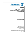
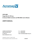
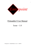
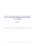
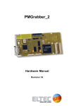
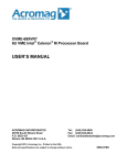
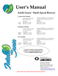
XVME-9076 Dual PMC Carrier Module for the XVME-6200 USER’S MANUAL ACROMAG INCORPORATED 30765 South Wixom Road P.O. BOX 437 Wixom, MI 48393-7037 U.S.A. Tel: (248) 295-0885 Fax: (248) 624-9234 Email: [email protected] Copyright 2012, Acromag, Inc., Printed in the USA. Data and specifications are subject to change without notice. 8500-982C XVME-9076 User Manual 1. Functional Overview The XMVE-9076 is a carrier board designed to provide two PMC expansion ports to an XVME-6200 series processor board. The carrier uses four lanes of PCI Express as its interface to the processor board, and uses an Intel bridge device to generate two independent channels of PCI-X. The XVME9076 supports 3.3V, 133MHz signaling on each PMC site and can be configured for slower speeds including 33MHz PCI. Onboard regulation provides 3.3V and 1.5V to the bridge chip and PMC sites. 5V signaling is not supported by this model and the board is keyed to 3.3V signaling only. Key features of the XVME-9076 include: • High-speed connection to the XVME-6200 processor board, using four lanes of PCI Express capable of 1GB/second bandwidth in each direction. • Support for PMC cards at speeds up to 133Mhz. • 3.3V-tolerant signaling using 64-bit PCI-X. • Dual-channel PMC support for two PCM cards, each with its own bus resources. • Seamless integration with an XVME-6200 processor board. 2. VLSI and Component Selection Several considerations drove the selection of the bridge device needed to translate the PCI Express link from the processor board into the PCI-X interface required by the PMC sites. These include: • • • • • Support for two channels of 64-bit PCI-X with dedicated bus resources for each channel Support for speeds up to 133MHz in dual-channel operation Source voltage less than or equal to the 5V supplied to the carrier board Sustainable production lifetime for 3 years or more Satisfaction of Xembedded environmental specifications Several devices were studied, including components from NEC and Intel. Ultimately, the device selected was the Intel 41210 PCIe-to-PCIX Bridge. This device meets the above criteria and allows for dual-channel operation in a seamless operational mode. The Intel 41210 has additional features that lend itself well to the design of the XVME-9076: • • • Configurable by an external microcontroller via SMBus. Efficient power consumption with a thermal profile suitable for in-stock heat sinks Selectable speed settings for debug assistance and end-user customization Xembedded Page 2 of 17 October 26, 2009 XVME-9076 User Manual 3. Architectural Block Diagram Figure 1 contains the functional block diagram of XVME-9090VR7 Remote I/O board. Figure #1: Block Diagram Xembedded Page 3 of 17 October 26, 2009 XVME-9076 User Manual 4. Installing the XVME-9076 on an XVME-6200 The XVME-9076 adapter module connects directly to the XVME-6200 via P5 interconnect connector. Additional hardware (supplied with the XVME-9076) needs to be mounted to the boards. • Three or Four corner standoffs (four are supplied. Some older XVME-6200’s can only be connected in three corners). • Three to four pairs of standoff screws (four parts are supplied. Some older XVME-6200’s can only be connected in three corners). The XVME-9076 and the XVME-6200 are shipped separately and are assembled by the integrator. NOTE: The XVME-9076 and the XVME-6200 will be damaged if the XVME-6200 and the XVME-9076 are not fasten together BEFORE inserting into the VMEbus chassis. AT NO TIME should these two modules be inserted without being fasten together. Damage will not be covered under warranty. Xembedded Page 4 of 17 October 26, 2009 XVME-9076 User Manual 4.1 Installing the XVME-9076 to the host XVME-6200Processor Module. 1. Follow procedures for the prevention of static discharge to prevent damage to the circuitry of the modules. 2. Disconnect all power sources. 3. Loosen the screws on the front panel of the XVME-6200processor module. 4. Remove the XVME-6200from the VME backplane, as follows: • Gently pull on the face plate until it slides out of the chassis Figure 4-1 Installing XVME-9076 to the XVME-6200 5. Place the XVME-6200 on a static-free surface with the P6 connector facing up. 6. Align the P5 connector on the XVME-9076 with the same connectors on the XVME-6200. 7. Gently press the two boards together. Do not bend or twist the XVME-9076. 8. Add standoffs (4) and standoff screws (4 pairs) as illustrated in Figure 4-1. Continue to use care not to bend or twist the modules while assembling them. 9. Clear two adjacent card cage slots. 10. Align the two connected modules (with the XVME-9076 on the right) on the card guides in the slots. 11. Gently push the modules to the rear of the chassis until the P1 and P2 connectors engage. 12. Tighten the screws on the front panel of the XVME-6200 processor module and the XVME9076 module to secure the connected modules into place. The installation is complete. Xembedded Page 5 of 17 October 26, 2009 XVME-9076 User Manual 5. Interconnect Definition The XVME-9076 supports the following interconnects to the processor board and the PMC sites. Connector VME P1 connector to backplane VME P2 connector to backplane VME P4 connector to backplane (typically called out as P0 on VME boards and optional) PCIe P5 connector to processor board J11-J14 PMC connectors J21-J24 PMC connectors Function Supplies power and required VME loopbacks Supplies power and PMC I/O to PMC site 1 Supplies PMC I/O to PMC site 2 Supplies PCIe interface between the XVME9076 and the processor board Supplies PMC connectors to PMC site 1 Supplies PMC connectors to PMC site 2 5.1 P1 Pin Definitions Pin Number A1 A2 A3 A4 A5 A6 A7 A8 A9 A10 A11 A12 A13 A14 A15 A16 A17 A18 A19 A20 A21 A22 A23 A24 A25 A26 A27 A28 Xembedded Signal NC NC NC NC NC NC NC NC GND NC GND NC NC NC GND NC GND NC GND NC VME_IACK_ IN_OUT# NC NC NC NC NC NC Pin Number B1 B2 B3 B4 B5 B6 B7 B8 B9 B10 B11 B12 B13 B14 B15 B16 B17 B18 B19 B20 B21 B22 B23 B24 B25 B26 B27 B28 Signal NC NC NC VME_BG_ IN_OUT0# VME_BG_ IN_OUT1# VME_BG_ IN_OUT2# VME_BG_ IN_OUT3# NC NC NC NC NC NC NC NC GND NC NC GND NC NC NC NC NC Page 6 of 17 Pin Number C1 C2 C3 C4 C5 C6 C7 C8 C9 C10 C11 C12 C13 C14 C15 C16 C17 C18 C19 C20 C21 C22 C23 C24 C25 C26 C27 C28 Signal NC NC NC NC NC NC NC NC GND NC NC NC NC NC NC NC NC NC NC NC NC NC NC NC NC NC NC NC October 26, 2009 XVME-9076 User Manual A29 A30 A31 A32 NC NC -12V +5V B29 B30 B31 B32 NC NC NC +5V C29 C30 C31 C32 NC NC +12V +5V Note: Power signals are called out in red. Xembedded Page 7 of 17 October 26, 2009 XVME-9076 User Manual 5.2 P2 Pin Definitions Pin Number A1 A2 A3 A4 A5 A6 A7 A8 A9 A10 A11 A12 A13 A14 A15 A16 A17 A18 A19 A20 A21 A22 A23 A24 A25 A26 A27 A28 A29 A30 A31 A32 Signal PMC1_IO2 PMC1_IO4 PMC1_IO6 PMC1_IO8 PMC1_IO10 PMC1_IO12 PMC1_IO14 PMC1_IO16 PMC1_IO18 PMC1_IO20 PMC1_IO22 PMC1_IO24 PMC1_IO26 PMC1_IO28 PMC1_IO30 PMC1_IO32 PMC1_IO34 PMC1_IO36 PMC1_IO38 PMC1_IO40 PMC1_IO42 PMC1_IO44 PMC1_IO46 PMC1_IO48 PMC1_IO50 PMC1_IO52 PMC1_IO54 PMC1_IO56 PMC1_IO58 PMC1_IO60 PMC1_IO62 PMC1_IO64 Pin Number B1 B2 B3 B4 B5 B6 B7 B8 B9 B10 B11 B12 B13 B14 B15 B16 B17 B18 B19 B20 B21 B22 B23 B24 B25 B26 B27 B28 B29 B30 B31 B32 Signal +5V GND NC NC NC NC NC NC NC NC NC GND +5V NC NC NC NC NC NC NC NC GND NC NC NC NC NC NC NC NC GND +5V Pin Number C1 C2 C3 C4 C5 C6 C7 C8 C9 C10 C11 C12 C13 C14 C15 C16 C17 C18 C19 C20 C21 C22 C23 C24 C25 C26 C27 C28 C29 C30 C31 C32 Signal PMC1_IO1 PMC1_IO3 PMC1_IO5 PMC1_IO7 PMC1_IO9 PMC1_IO11 PMC1_IO13 PMC1_IO15 PMC1_IO17 PMC1_IO19 PMC1_IO21 PMC1_IO23 PMC1_IO25 PMC1_IO27 PMC1_IO29 PMC1_IO31 PMC1_IO33 PMC1_IO35 PMC1_IO37 PMC1_IO39 PMC1_IO41 PMC1_IO43 PMC1_IO45 PMC1_IO47 PMC1_IO49 PMC1_IO51 PMC1_IO53 PMC1_IO55 PMC1_IO57 PMC1_IO59 PMC1_IO61 PMC1_IO63 Note: Power signals are called out in red. Xembedded Page 8 of 17 October 26, 2009 XVME-9076 User Manual 5.3 P4 (P0) Pin Definitions Pin A1 A2 A3 A4 A5 A6 A7 A8 A9 A10 A11 A12 A13 A14 A15 A16 A17 A18 A19 Signal NC NC NC NC NC NC PMC2_I0-5 PMC2_I0-10 PMC2_I0-15 PMC2_I0-20 PMC2_I0-25 PMC2_I0-30 PMC2_I0-35 PMC2_I0-40 PMC2_I0-45 PMC2_I0-50 PMC2_I0-55 PMC2_I0-60 NC Pin B1 B2 B3 B4 B5 B6 B7 B8 B9 B10 B11 B12 B13 B14 B15 B16 B17 B18 B19 Signal NC NC NC NC NC NC PMC2_I0-4 PMC2_I0-9 PMC2_I0-14 PMC2_I0-19 PMC2_I0-24 PMC2_I0-29 PMC2_I0-34 PMC2_I0-39 PMC2_I0-44 PMC2_I0-49 PMC2_I0-54 PMC2_I0-59 PMC2_I0-64 Pin C1 C2 C3 C4 C5 C6 C7 C8 C9 C10 C11 C12 C13 C14 C15 C16 C17 C18 C19 Signal NC GND GND GND GND NC PMC2_I0-3 PMC2_I0-8 PMC2_I0-13 PMC2_I0-18 PMC2_I0-23 PMC2_I0-28 PMC2_I0-33 PMC2_I0-38 PMC2_I0-43 PMC2_I0-48 PMC2_I0-53 PMC2_I0-58 PMC2_I0-63 Pin D1 D2 D3 D4 D5 D6 D7 D8 D9 D10 D11 D12 D13 D14 D15 D16 D17 D18 D19 Signal NC NC NC NC NC NC PMC2_I0-2 PMC2_I0-7 PMC2_I0-12 PMC2_I0-17 PMC2_I0-22 PMC2_I0-27 PMC2_I0-32 PMC2_I0-37 PMC2_I0-42 PMC2_I0-47 PMC2_I0-52 PMC2_I0-57 PMC2_I0-62 Pin E1 E2 E3 E4 E5 E6 E7 E8 E9 E10 E11 E12 E13 E14 E15 E16 E17 E18 E19 Signal NC NC NC NC NC NC PMC2_I0-1 PMC2_I0-6 PMC2_I0-11 PMC2_I0-16 PMC2_I0-21 PMC2_I0-26 PMC2_I0-31 PMC2_I0-36 PMC2_I0-41 PMC2_I0-46 PMC2_I0-51 PMC2_I0-56 PMC2_I0-61 Pin F1 F2 F3 F4 F5 F6 F7 F8 F9 F10 F11 F12 F13 F14 F15 F16 F17 F18 F19 Signal GND GND GND GND GND GND GND GND GND GND GND GND GND GND GND GND GND GND GND Note: Power signals are called out in red. Xembedded Page 9 of 17 October 26, 2009 XVME-9076 User Manual 5.4 P5 Pin Definitions Pin Number 1 3 5 7 9 11 13 15 17 19 21 23 25 27 29 31 33 35 37 39 41 43 Signal GND PCIE_XMT_LN0_DN PCIE_XMT_LN0_DP GND PCIE_XMT_LN1_DN PCIE_XMT_LN1_DP GND PCIE_XMT_LN2_DN PCIE_XMT_LN2_DP GND PCIE_XMT_LN3_DN PCIE_XMT_LN3_DP GND GND GND GND CK_100M_PCIE_DP CK_100M_PCIE_DN GND GND GND GND Pin Number 2 4 6 8 10 12 14 16 18 20 22 24 26 28 30 32 34 36 38 40 42 Signal GND PCIE_RCV_LN0_DN PCIE_RCV_LN0_DP GND PCIE_RCV_LN1_DN PCIE_RCV_LN1_DP GND PCIE_RCV_LN2_DN PCIE_RCV_LN2_DP GND PCIE_RCV_LN3_DN PCIE_RCV_LN3_DP GND GND GND GND GND RST_PCIE# GND GND GND 5.5 J11-J24 Pin Definitions J11, J21 Pin Number 1 3 5 7 9 11 13 15 17 19 21 23 25 27 29 31 33 Xembedded Signal TCK GND INTB* BUSMODE1* INTD* GND CLK GND REQ* V_I/O PAD(28) PAD(25) GND PAD(22) PAD(19) V_I/O FRAME* Pin Number 2 4 6 8 10 12 14 16 18 20 22 24 26 28 30 32 34 Signal -12V INTA* INTC* +5V PCI-RSVD14B PCI-RSVD GND GNT* +5V PAD(31) PAD(27) GND C_BE3* PAD(21) +5V PAD(17) GND Page 10 of 17 October 26, 2009 XVME-9076 User Manual 35 37 39 41 43 45 47 49 51 53 55 57 59 61 63 GND DEVSEL* GND SDONE PAR V_I/O PAD(12) PAD(9) GND PAD(6) PAD(4) V_I/O PAD(2) PAD(0) GND 36 38 40 42 44 46 48 50 52 54 56 58 60 62 64 IRDY* +5V PLOCK* SBO GND PAD(15) PAD(11) +5V C_BE0* PAD(5) GND PAD(3) PAD(1) +5V REQ64* J12, J22 Pin Number 1 3 5 7 9 11 13 15 17 19 21 23 25 27 29 31 33 35 37 39 41 43 45 47 49 51 53 55 57 59 61 63 Name +12V TMS TDI GND PCI-RSVD* BUSMODE2* RST* +.3V PCI-RSVD* PAD(30) GND PAD(24) IDSEL +3.3V PAD(18) PAD(16) GND TRDY* GND PERR* +3.3V C_BD1* PAD(14) GND PAD(8) PAD(7) +3.3V PMC-RSVD PMC-RSVD GND ACK64* GND Pin Number 2 4 6 8 10 12 14 16 18 20 22 24 26 28 30 32 34 36 38 40 42 44 46 48 50 52 54 56 58 60 62 64 Name TRST* TDO GND PCI-RSVD* PCI-RSVD* +3.3V BUSMODE3* BUSMODE4* GND PAD(29) PAD(26) +3.3V PAD(23) pad(20) GND C_BD2* PMC-RSVD +3.3V STOP* GND SERR* GND PAD(13) PAD(10) +3.3V PMC-RSVD PMC-RSVD GND PMC-RSVD PMC-RSVD +3.3V PMC-RSVD Xembedded Page 11 of 17 October 26, 2009 XVME-9076 User Manual J13/J23 Pin Number 1 3 5 7 9 11 13 15 17 19 21 23 25 27 29 31 33 35 37 39 41 43 45 47 49 51 53 55 57 59 61 63 Name NC GND C/BE6# C/BE4# +3.3V PAD(63) PAD(61) GND PAD(59) PAD(57) +3.3V PAD(55) PAD(53) GND PAD(51) PAD(49) GND PAD(47) PAD(45) +3.3V PAD(43) PAD(41) GND PAD(39) PAD(37) GND PAD(35) PAD(33) +3.3V NC NC GND Pin Number 2 4 6 8 10 12 14 16 18 20 22 24 26 28 30 32 34 36 38 40 42 44 46 48 50 52 54 56 58 60 62 64 Name GND C/BE7# C/BE5# GND PAR64 PAD(62) GND PAD(60) PAD(58) GND PAD(56) PAD(54) GND PAD(52) PAD(50) GND PAD(48) PAD(46) GND PAD(44) PAD(42) GND PAD(40) PAD(38) GND PAD(36) PAD(34) GND PAD(32) NC GND NC J14/J24 Pin Number 1 3 5 7 9 11 13 15 17 19 21 23 25 Name USER I/O - 1 USER I/O - 3 USER I/O - 5 USER I/O - 7 USER I/O - 9 USER I/O - 11 USER I/O - 13 USER I/O - 15 USER I/O - 17 USER I/O - 19 USER I/O - 21 USER I/O - 23 USER I/O - 25 Pin Number 2 4 6 8 10 12 14 16 18 20 22 24 26 Name USER I/O - 2 USER I/O - 4 USER I/O - 6 USER I/O - 8 USER I/O - 10 USER I/O - 12 USER I/O - 14 USER I/O - 16 USER I/O - 18 USER I/O - 20 USER I/O - 22 USER I/O - 24 USER I/O - 26 Xembedded Page 12 of 17 October 26, 2009 XVME-9076 User Manual 27 29 31 33 35 37 39 41 43 45 47 49 51 53 55 57 59 61 63 USER I/O - 27 USER I/O - 29 USER I/O - 31 USER I/O - 33 USER I/O - 35 USER I/O - 37 USER I/O - 39 USER I/O - 41 USER I/O - 43 USER I/O - 45 USER I/O - 47 USER I/O - 49 USER I/O - 51 USER I/O - 53 USER I/O - 55 USER I/O - 57 USER I/O - 59 USER I/O - 61 USER I/O - 63 28 30 32 34 36 38 40 42 44 46 48 50 52 54 56 58 60 62 64 USER I/O - 28 USER I/O - 30 USER I/O - 32 USER I/O - 34 USER I/O - 36 USER I/O - 38 USER I/O - 40 USER I/O - 42 USER I/O - 44 USER I/O - 46 USER I/O - 48 USER I/O - 50 USER I/O - 52 USER I/O - 54 USER I/O - 56 USER I/O - 58 USER I/O - 60 USER I/O - 62 USER I/O - 64 6. Functional Configuration Options 6.1 Jumpers The following table Lists XVME-9090 jumpers, their default positions, and their functions. Jumper ORBGND Position Not populated Pins 1-2 Pins 2-3 CONFIG Not populated Pins 1-2 Pins 2-3 denotes default Xembedded Function Chassis ground isolated from digital ground Chassis ground isolated from digital ground Chassis ground isolated tied to digital ground Use 41210 default values at startup Use 41210 default values at startup Load 41210 configuration data from µcontroller Page 13 of 17 October 26, 2009 XVME-9076 User Manual Xembedded Page 14 of 17 October 26, 2009 XVME-9076 User Manual 6.2 Switches SW1 on the XVME-9076 is a 4 position DIP switch used to manually assign SMBus addresses for the Intel 41210 Bridge device. Position 1 2 3 4 Open SMBus 1 set to 3.3V SMBus 2 set to 3.3V SMBus 3 set to 3.3V SMBus 5 set to 3.3V Closed SMBus 1 set to 0V SMBus 2 set to 0V SMBus 3 set to 0V SMBus 5 set to 0V SW2 and SW3 on the XVME-9076 are 4 position DIP switches used to control the bus speed on PMC site 1 and PMC site 2, respectively. The switches set combinatorial logic to dictate the bus speed and specific bus interface used for each PMC site as illustrated in the truth table below: 7. Performance The XVME-9076 is designed to perform to its intended design targets, including PCI-X bus transfers at speeds up to 133MHz. Performance versus its predecessor design, the XVME-9076, is expected to be superior due to the faster PCI Express interface to the processor board and the Intel 41210 bridge device, which supports higher PCI-X speeds than were supported on the XVME-976-2X9. Thermal performance is expected to scale with higher operational speeds at the PMC sites. The thermal solution used for the XVME-9076 requires a minimum of 200 CFM of airflow to maintain proper thermal protection of the Intel 41210 bridge device. 8. Top-Level Assemblies The XVME-9076 is available in three top-level assemblies, all of which use the Xembedded XVME9076-099 PCBA as the base assembly. The top-level assemblies are defines as follows: TOP-LEVEL PART XVME-9076-309 XVME-9076-319 XVME-9076-329 Xembedded HANDLE TYPE VME-style handles Compact PCI-style handles VME-style handles Page 15 of 17 P0 CONNECTOR Not populated Not populated Populated October 26, 2009 XVME-9076 User Manual XVME-9076-339 Compact PCI-style handles Populated All Top-level assemblies include PMC cover plates and shipping labels, 9. Product Specifications and Ratings The XVME-9076 meets the following environmental requirements. 9.1 Environmental Specifications The XVME-9076 is designed to meet the following environmental requirements: Environmental Specification Non-Operating Thermal -20C to 70 C with 200CFM airflow -40 to 85 C Humidity 10% to 90% RH, noncondensing 10% to 90% RH, non-condensing Shock 30 g peak acceleration, 50 g peak acceleration, 11 msec duration 11 msec duration 0.015” (0.38mm) peak-topeak displacement, 2.5 g maximum acceleration 0.030” (0.76mm) peak-to-peak displacement, 5 g maximum acceleration Vibration 5 – 2000 Hz Xembedded Operating Page 16 of 17 October 26, 2009 XVME-9076 User Manual 9.2 Compliance Specifications / Agency Approvals The XVME-9076 is designed to meet CE Emissions specification EN 55022 and CE Immunity specification EN 50082-2, and FCC 47 CFR, Part 15, Class A when tested in a shielded enclosure. 10. Power Requirements The following power requirements include power for the Intel 41210 bridge device and the two PMC sites. Required voltage Tolerances Permissive ripple Max. Current Requirement +5 Volts 50mVp-p 12A +0.25V / -0.125V Ripple and noise measurements shall be made under all specified load conditions through a single-pole low pass filter with 10 MHz cutoff frequency. Xembedded Page 17 of 17 October 26, 2009