1
PX Developer Version 1
Operating Manual
(JoyWatcherSuite Interactio)
-SW1D5C-FBDQ-E
-SW1D5C-FBDQMON-E
SAFETY PRECAUTIONS
(Always read these instructions before using this product.)
Before using this product, thoroughly read this manual and the relevant manuals introduced in this
manual and pay careful attention to safety and handle the products properly.
The precautions given in this manual are concerned with this product. For the safety precautions of the
programmable controller system, refer to the User’s Manual for the CPU module.
In this manual, the safety precautions are ranked as " ! WARNING" and " ! CAUTION".
! WARNING
! CAUTION
Indicates that incorrect handling may cause hazardous conditions,
resulting in death or severe injury.
Indicates that incorrect handling may cause hazardous conditions,
resulting in minor or moderate injury or property damage.
Note that the ! CAUTION level may lead to serious consequences according to the circumstances.
Always follow the precautions of both levels because they are important for personal safety.
Please save this manual to make it accessible when required and always forward it to the end user.
[Startup/Maintenance Precautions]
!
CAUTION
The online operations have to be executed after the manual has been carefully read and the
safety has been ensured.
Failure to do so may cause a miss operation which results in machine damage or an accident.
A-1
A-1
CONDITIONS OF USE FOR THE PRODUCT
(1) Mitsubishi programmable controller ("the PRODUCT") shall be used in conditions;
i) where any problem, fault or failure occurring in the PRODUCT, if any, shall not lead to any major or
serious accident; and
ii) where the backup and fail-safe function are systematically or automatically provided outside of the
PRODUCT for the case of any problem, fault or failure occurring in the PRODUCT.
(2) The PRODUCT has been designed and manufactured for the purpose of being used in general
industries.
MITSUBISHI SHALL HAVE NO RESPONSIBILITY OR LIABILITY (INCLUDING, BUT NOT LIMITED
TO ANY AND ALL RESPONSIBILITY OR LIABILITY BASED ON CONTRACT, WARRANTY, TORT,
PRODUCT LIABILITY) FOR ANY INJURY OR DEATH TO PERSONS OR LOSS OR DAMAGE TO
PROPERTY CAUSED BY the PRODUCT THAT ARE OPERATED OR USED IN APPLICATION NOT
INTENDED OR EXCLUDED BY INSTRUCTIONS, PRECAUTIONS, OR WARNING CONTAINED IN
MITSUBISHI'S USER, INSTRUCTION AND/OR SAFETY MANUALS, TECHNICAL BULLETINS AND
GUIDELINES FOR the PRODUCT.
("Prohibited Application")
Prohibited Applications include, but not limited to, the use of the PRODUCT in;
Nuclear Power Plants and any other power plants operated by Power companies, and/or any other
cases in which the public could be affected if any problem or fault occurs in the PRODUCT.
Railway companies or Public service purposes, and/or any other cases in which establishment of a
special quality assurance system is required by the Purchaser or End User.
Aircraft or Aerospace, Medical applications, Train equipment, transport equipment such as Elevator
and Escalator, Incineration and Fuel devices, Vehicles, Manned transportation, Equipment for
Recreation and Amusement, and Safety devices, handling of Nuclear or Hazardous Materials or
Chemicals, Mining and Drilling, and/or other applications where there is a significant risk of injury to
the public or property.
Notwithstanding the above, restrictions Mitsubishi may in its sole discretion, authorize use of the
PRODUCT in one or more of the Prohibited Applications, provided that the usage of the PRODUCT is
limited only for the specific applications agreed to by Mitsubishi and provided further that no special
quality assurance or fail-safe, redundant or other safety features which exceed the general
specifications of the PRODUCTs are required. For details, please contact the Mitsubishi
representative in your region.
A-2
A-2
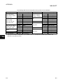
REVISIONS
*The manual number is given on the bottom left of the back cover.
Print Date
Dec., 2010
Oct., 2011
* Manual Number
SH(NA)-080976ENG-A
SH(NA)-080976ENG-B
Revision
First edition
Addition
Appendix 5
Correction
HOW TO USE THIS MANUAL, Section 1.1, Section 3.5,
Section 3.5.4, Chapter 4, Appendix 2, Appendix 3.1, Appendix 3.2
Feb., 2014
SH(NA)-080976ENG-C
Addition
Appendix 6
Correction
GENERIC TERMS, ABBREVIATIONS, AND TERMS, Section 2.3,
Section 3.6.1, Appendix 2
Jul., 2015
SH(NA)-080976ENG-D
Correction
Section 3.3.1
Japanese Manual Version SH-080922-I
This manual confers no industrial property rights or any rights of any other kind, nor does it confer any patent
licenses. Mitsubishi Electric Corporation cannot be held responsible for any problems involving industrial property
rights which may occur as a result of using the contents noted in this manual.
2010 MITSUBISHI ELECTRIC CORPORATION
A-3
A-3
INTRODUCTION
Thank you for choosing the Mitsubishi MELSOFT series Integrated FA software.
Read this manual and make sure you understand the functions and performance of MELSOFT series
thoroughly in advance to ensure correct use.
CONTENTS
SAFETY PRECAUTIONS................................................................................................................................A-1
CONDITIONS OF USE FOR THE PRODUCT ...............................................................................................A-2
REVISIONS ......................................................................................................................................................A-3
INTRODUCTION..............................................................................................................................................A-4
CONTENTS......................................................................................................................................................A-4
MANUALS ........................................................................................................................................................A-6
HOW TO USE THIS MANUAL ........................................................................................................................A-7
MANUAL ORGANIZATION .............................................................................................................................A-9
GENERIC TERMS, ABBREVIATIONS, AND TERMS .................................................................................A-10
1
OVERVIEW .............................................................................................................................................. 1-1
1.1
1.2
2
SYSTEM CONFIGURATION ................................................................................................................... 2-1
2.1
2.2
2.3
3
Overview............................................................................................................................................... 1-1
Features ............................................................................................................................................... 1-2
System Configuration........................................................................................................................... 2-1
Software Configuration ........................................................................................................................ 2-3
Operating Environment ........................................................................................................................ 2-4
BASIC OPERATION ................................................................................................................................ 3-1
3.1
Operating Procedures for Monitoring on JoyWatcherSuite................................................................ 3-1
3.2
Operation to Set PX Developer Projects to be Monitored on Monitor Tool ....................................... 3-2
3.2.1 Setting monitor target projects......................................................................................................... 3-2
3.3
Operation to Communicate using PX Developer Process Control Tag Names in
JoyWatcherSuite .................................................................................................................................. 3-3
3.3.1 Registering process control tags ..................................................................................................... 3-4
3.3.2 Server design ................................................................................................................................... 3-6
3.3.3 Referring to and selecting process control tags.............................................................................. 3-9
3.4
Operation to Use Faceplates of PX Developer in JoyWatcherSuite................................................ 3-12
3.4.1 Pasting/setting faceplate control.................................................................................................... 3-13
3.4.2 Setting of showing faceplate from object ...................................................................................... 3-15
3.5
Operation to Display PX Developer Alarm/Event Information on Alarm Monitor of
JoyWatcherSuite ................................................................................................................................ 3-18
3.5.1 Configuring database settings ....................................................................................................... 3-21
3.5.2 Server design ................................................................................................................................. 3-22
3.5.3 Setting security manager ............................................................................................................... 3-25
3.5.4 Setting alarm monitor..................................................................................................................... 3-29
3.6
Operation to Perform Interactive Start/Stop of PX Developer Monitor Tool on JoyWatcherSuite .. 3-32
3.6.1 Setting interactive start/stop of monitor tool .................................................................................. 3-33
3.6.2 Setting interactive start/stop of security manager ......................................................................... 3-34
A-4
A-4
TROUBLESHOOTING ............................................................................................................................. 4-1
4
APPENDIX..........................................................................................................................................................B-1
Appendix 1 Data Types of Process Control Tag Items ..............................................................................B-1
Appendix 2 Main Tag Items.........................................................................................................................B-1
Appendix 3 Correspondence Table for Items of Monitor Tool and JoyWatcherSuite ...............................B-3
Appendix 3.1 Correspondence table for alarm items...............................................................................B-3
Appendix 3.2 Correspondence table for event items ...............................................................................B-4
Appendix 4 Calling Monitor Tool Function from JoyWatcherSuite ............................................................B-5
Appendix 5 Security of Monitor Tool and JoyWatcherSuite.......................................................................B-6
Appendix 5.1 Operating environment for using security of monitor tool and JoyWatcherSuite .............B-6
Appendix 5.2 Setting procedure for using security of monitor tool and JoyWatcherSuite......................B-6
Appendix 5.3 Procedure for monitoring operation with security interaction between monitor tool and
JoyWatcherSuite...............................................................................................................B-13
Appendix 6 Functions Added to and Changed from Old Version ............................................................B-14
NDEX ..................................................................................................................................................................C-1
A-5
A-5
MANUALS
The following manuals are also related to this product.
Refer to the following table for ordering a manual.
Related manuals
Manual number
(model code)
Manual name
PX Developer Operating Manual (Programming Tool)
Explains FBD language programming, compilation, online operations, and debug methods with PX
Developer.
(Sold separately.)
PX Developer Operating Manual (Monitor Tool)
Explains the operation methods of the monitor tool and methods for monitoring and controlling DDC
processing with tag FB.
(Sold separately.)
PX Developer Programming Manual
Explains details of programming with PX Developer, lists of FB parts, and the PID instructions.
SH-080369E
(13JU38)
SH-080370E
(13JU39)
SH-080371E
(13JW00)
(Sold separately.)
CAUTION
• Please note that we do not guarantee commercially available software
compatible with Microsoft Windows Operating System introduced in this
manual.
• The software copyright of this product belongs to Mitsubishi Electric Corporation.
• No contents in this manual can be reproduced or duplicated in any form or by any
means without permission.
• Although we make utmost efforts, this manual may not completely follow the
revisions of the software and hardware.
• In principle, this software should be purchased by one set per personal computer
or by license purchase.
• This product (including this manual) can only be used under the software license
agreement.
• Please note that we are not responsible for any influence resulting from operating
this product (including this manual).
• The contents of this manual are subject to change without notice.
R
A-6
R
A-6
HOW TO USE THIS MANUAL
PURPOSE
Describes the purpose of operations for
each chapter or section.
Execution on JoyWatcherSuite
Describes functions to be executed.
A-7
Setting on JoyWatcherSuite
Describes operating procedures.
Reference location
leads to the reference location.
A-7
There are also the following types of explanations.
BASIC OPERATION
Explains operation methods.
DISPLAY/SETTING SCREEN
Screen to display/set items.
DISPLAY/SETTING DATA
Explains items in DISPLAY/SETTING SCREEN.
POINT
Informs items to be noted and useful functions relevant to the contents in the chapter or section.
The following table explains symbols in this manual and their description.
Symbol
[
]
(
)
"
"
<<
A-8
>>
Description
Expresses an item in a window or dialog box, or a menu on the menu bar.
[ ] [ ] expresses the drop-down menu.
Example: [File] [Save As]
Expresses a corresponding button.
Example: " Select " button (
)
Expresses a command button.
Example: "OK" button
Expresses dialog box tab.
Example: <<MELSEC PX ALARM>> tab
A-8
MANUAL ORGANIZATION
This manual consists of four chapters and Appendix.
This manual is organized assuming that the interaction function of the PX Developer
monitor tool and JoyWatcherSuite are utilized in the following procedure.
< Procedure for utilizing the interaction function with JoyWatcherSuite >
Operating procedure 1: Set PX Developer projects to be monitored
on the PX Developer monitor tool.
• Set monitor target projects.
Operating procedure 2: Using the tag name reference function of
JoyWatcherSuite, assign process control
tags of PX Developer to the tags.
Reference
Section 3.2
• PX Developer Operating Manual
(Monitor Tool)
Reference
• Register process control tags to be used.
• Set the settings to communicate with PX Developer.
Section 3.3
• Set process control tags to be monitored.
Operating procedure 3: Paste faceplate control of PX Developer
monitor tool on JWEdit of JoyWatcherSuite.
• Paste/set faceplate control.
• Set showing faceplate from object.
Operating procedure 4: Set to display alarms and events of the PX
Developer monitor tool on Alarm Monitor of
JoyWatcherSuite.
Reference
Section 3.4
Reference
• Set the database settings.
• Set common memory devices.
• Set the security manager.
Section 3.5
• Set the alarm monitor.
Operating procedure 5: Set to perform interactive start/stop of the
PX Developer monitor tool on
JoyWatcherSuite.
Reference
• Set the interactive start/stop setting.
Section 3.6
Operating procedure 6: Execute JWPanel of JoyWatcherSuite.
A-9
A-9
GENERIC TERMS, ABBREVIATIONS, AND TERMS
The following table shows the generic terms, abbreviations, and terms in this manual.
(1) Generic terms and abbreviations
Generic term/abbreviation
PX Developer
Programming tool
Monitor tool
OPS
Description
Generic term for PX Developer Version 1 (SW1D5C-FBDQ-E) and PX Developer
Monitor Tool (SW1DNC-FBDQMON-E)
For PX Developer, Programming Tool and Monitor Tool are installed.
For PX Developer Monitor Tool, only Monitor Tool is installed.
Abbreviation for PX Developer programming tool
Abbreviation for PX Developer monitor tool
Abbreviation for Operator Station
Abbreviation for a monitor tool which starts up as Server in the server/client monitoring
system interacting with multiple OPSs
Server
Abbreviation for a monitor tool which starts up as Client in the server/client monitoring
system interacting with multiple OPSs
Client
JoyWatcherSuite
R
Windows 8
R
Windows 7
Windows Vista
R
Personal computer
Abbreviation for JoyWatcherSuite Version 5.0 or later
R
R
Generic term for Microsoft Windows 8 Operating System,
R
R
Microsoft Windows 8 Pro Operating System, and
R
R
Microsoft Windows 8 Enterprise Operating System
R
R
Generic term for Microsoft Windows 7 Starter Operating System,
R
R
Microsoft Windows 7 Home Premium Operating System,
R
R
Microsoft Windows 7 Professional Operating System,
R
R
Microsoft Windows 7 Ultimate Operating System, and
R
R
Microsoft Windows 7 Enterprise Operating System
R
R
Generic term for Microsoft Windows Vista Home Basic Operating System,
R
R
Microsoft Windows Vista Home Premium Operating System,
R
R
Microsoft Windows Vista Business Operating System,
R
R
Microsoft Windows Vista Ultimate Operating System, and
R
R
Microsoft Windows Vista Enterprise Operating System
Generic term for IBM-PC/AT-compatible personal computer
(2) Terms
Term
Description
JWDesign
JWEdit
Alarm Monitor
Development environment of JoyWatcherSuite
Development environment of JoyWatcherSuite
Development environment of JoyWatcherSuite
MELSEC PX Tag Select
Security Manager
Development environment of JoyWatcherSuite
Development/Operating environment of JoyWatcherSuite
JWPanel
JWLauncher
Operating environment of JoyWatcherSuite
Operating environment of JoyWatcherSuite
DDE
DDC
FB
Process control tag
A-10
Abbreviation for Dynamic Data Exchange
R
Windows standard communication protocol between applications.
Abbreviation for Direct Digital Control
A control of controller functions with a digital device.
Abbreviation for Function Block
A block with a specific function used in a program.
Tags for identification attached to process control equipment.
They are JIS-defined identification symbols attached to DDC processings.
A-10
Term
Process control tag data
Process control tag data item
Tag FB
Description
Organized data (process condition data, process status data) attached to DDC
processing which is indicated by process control tag.
Accessing this process control tag data allows monitoring and condition setting of a
corresponding DDC processing.
Each data item that makes up process control tag data.
A function block works as a controller or an indicator containing tag data.
Faceplate
Gauge window on which an indicator such as a controller is displayed in image format.
Values assigned to tag data are manipulated.
SV
PV
Setting value
Process variable
MV
Manipulated variable
Assignment information
database
"*.mdb" file which is created when compilation is executed in the programming tool.
This file stores assignment information of variables for storing data such as tag data and
device information of the CPU module.
A-11
A-11
1 OVERVIEW
MELSOFT
1 OVERVIEW
1 1.1 Overview
In addition to the basic monitoring function of the monitor tool, outstanding and easyto-use JoyWatcherSuite development/monitoring environment can also be available by
using the interaction function of the PX Developer monitor tool and JoyWatcherSuite
(SCADA software manufactured by JT Engineering inc.).
This function supports the following four interaction functions.
(1) Incorporating faceplate control
(2) Communication function using process control tag names
(3) Reference function for PX Developer process control tag names
(4) Alarm integration function
The following are the development environment and operating environment of
JoyWatcherSuite described in this manual.
Development environment: JWDesign, JWEdit, Alarm Monitor, MELSEC PX Tag
Select, Security Manager, JWUserDef
Operating environment:
JWPanel, JWLauncher, Security Manager
1-1
1-1
1 OVERVIEW
MELSOFT
1.2 Features
1
This section explains the main features of the four interaction functions.
(1) Faceplate control reduces development time of monitor screens
By simply pasting faceplate control of PX Developer (ActiveX control) on JWEdit,
faceplates can be easily used on monitor screens of JoyWatcherSuite.
This reduces development time of monitor screens and tuning screens for
process control tag data on JoyWatcherSuite.
[Image of incorporating faceplate control]
PX Developer
faceplate control
JoyWatcherSuite
operating environment
PX Developer
monitor tool
Reading/writing
process control
tag data
Polling process
control tag data
PLC
Faceplates can be used by simply pasting
ActiveX control on JWEdit.
1-2
1-2
1 OVERVIEW
MELSOFT
(2) Without considering assigned devices, communications can be
performed using process control tag names in JoyWatcherSuite
When registering tags in JoyWatcherSuite, PX Developer process control tag
names can be used as tag names in JoyWatcherSuite, and process control tag
data in the monitor tool can be read from/written to JoyWatcherSuite.
This eliminates the need for managing assigned devices and communicating
through a communication driver to read/write process control tag data.
Furthermore, high-speed response by the event notification receive function and
the high-speed current value collection function of the monitor tool can be utilized
on the monitor screen of JoyWatcherSuite.
[Image of the communication function using process control tag names]
JoyWatcherSuite
operating environment
PX Developer
monitor tool
PV value of
the process
control tag FIC001
Reading/writing process
control tag data
High-speed current value collection
Event notification receive
Registration of tag with the
process control tag name
"FIC001_PV"
Unnecessary for reading/writing
process control tag data.
Communication
driver
Without considering assigned devices for the process control tags,
communications can be performed by registering tags on JoyWatcherSuite,
using process control tag names defined in PX Developer.
1-3
1-3
1 OVERVIEW
MELSOFT
(3) Process control tag names can be selected easily from
JoyWatcherSuite
When using the communication function with the aforementioned process control
tag name, PX Developer process control tag names can be easily
*1
browsed/selected by MELSEC PX Tag Select of JoyWatcherSuite using the tag
name reference function.
This function reduces key inputs and typing errors, and improves work efficiency.
*1: Process control tags that can be browsed/selected are tags of the project
registered in the monitor target project setting in the PX Developer monitor
tool.
[Image of the tag name reference function]
PX Developer
Selection of tags to be used in JoyWatcherSuite
PX Developer
programming tool
Assignment
information
database
JoyWatcherSuite
MELSEC PX Tag Select
Compilation
PX Developer
monitor tool
Monitor target
project setting
Tag information acquisition
Process control tag names defined in PX Developer can be
browsed/selected by MELSEC PX Tag Select of
JoyWatcherSuite
1-4
1-4
1 OVERVIEW
MELSOFT
(4) Alarms/events of the PX Developer monitor tool can be monitored
on JoyWatcherSuite
By using the alarm integration function, alarms and events of the monitor tool can
be displayed on Alarm Monitor of JoyWatcherSuite. This function improves
monitoring efficiency.
[Image of the alarm integration function]
JoyWatcherSuite
operating environment
PX Developer
monitor tool
Management on alarms/events
Management on alarms/events
Notification of alarms/events
Notification of alarms/events
PLC
1-5
Alarms/events of PX Developer can be monitored
on the alarm monitor of JoyWatcherSuite.
1-5
2 SYSTEM CONFIGURATION
MELSOFT
2 SYSTEM CONFIGURATION
2.1 System Configuration
This section explains system configuration when using the interaction function of PX
Developer and JoyWatcherSuite.
For communication routes supported by PX Developer, refer to "SYSTEM
CONFIGURATION" in "PX Developer Operating Manual (Monitor Tool)".
To use the interaction function, install PX Developer and JoyWatcherSuite to the same
personal computer. If they are installed to different personal computers, the interaction
function cannot be used.
[System configuration image]
English version of
PX Developer Version
1.28E or later
English version of
JoyWatcherSuite
Version 6.0 or later
Use a communication driver
depending on the situation.*1
Communication route supported by the
PX Developer monitor tool
*1: For reading/writing device data other than process control tags in JoyWatcherSuite,
a communication driver is required.
2-1
2-1
2
2 SYSTEM CONFIGURATION
MELSOFT
The following tables show the validation/invalidation of the interaction function
according to the combination of monitor tool and JoyWatcherSuite.
*1
Monitor tool
2
JoyWatcherSuite
Not installed
Server
Client
Reference function for PX Developer
process control tag name
Faceplate control display
Communication function using process
*2
control tag names
*2
Alarm integration function
( : Validated, : Invalidated)
Installed and not started
*1
Monitor tool
Server
Standalone
JoyWatcherSuite
Server
Client
Client
Reference function for PX Developer
process control tag names
Faceplate control display
Communication function using process
*2
control tag names
*2
Alarm integration function
( : Validated, : Invalidated)
In operation
*1
Monitor tool
Server
Standalone
JoyWatcherSuite
Server
Client
Client
Reference function for PX Developer
process control tag names
Faceplate control display
Communication function using process
*2
control tag names
Alarm integration function
*2
( : Validated, : Invalidated)
*1: Install a monitor tool server or standalone to a JoyWatcherSuite server, and install a
monitor tool client to a JoyWatcherSuite client.
*2: Validated only when the monitor tool is in operation on the JoyWatcherSuite server
personal computer.
2-2
2-2
2 SYSTEM CONFIGURATION
MELSOFT
2.2 Software Configuration
This section explains software configuration when using the interaction function of PX
Developer and JoyWatcherSuite.
PX Developer
JoyWatcherSuite
Monitor target
project setting
Development environment
Reference
Operating environment
Monitor tool
Paste
Faceplate control
ActiveX container function
Alarm/Event
Alarm/event interaction function
Data
management
PLC
Tag name reference function
DDE
interface*1
Notification
Process control
tag data
communication
Alarm/Even
Security manager*2
DDE
interface
Data
management
Data communication other than
process control tags
Data communication
Data communication
Communication driver
*1: JoyWatcherSuite reads/writes process control tag data in the PX Developer
monitor tool through DDE interface.
*2: The security manager is an application that stores information on alarms and
events to the alarm database of JoyWatcherSuite.
2-3
2-3
2 SYSTEM CONFIGURATION
MELSOFT
2.3 Operating Environment
PX Developer Version 1.28E or later and JoyWatcherSuite Version 6.0 or later are
required for interacting themselves.
For the operating environment of PX Developer, refer to "Operating Environment" in
"PX Developer Operating Manual (Monitor Tool)".
For the operating environment of JoyWatcherSuite, refer to "Start Guide" of
JoyWatcherSuite.
The following are the applicable system software (operating system) to operate this
interaction function.
• Microsoft Windows 2000 Operating system
• Microsoft Windows XP Home Edition Operating system
• Microsoft Windows XP Professional Operating system
• Windows Vista
• Windows 7
• Windows 8
R
R
R
R
R
R
R
R
R
2-4
2-4
3 BASIC OPERATION
MELSOFT
3 BASIC OPERATION
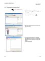
3.1 Operating Procedures for Monitoring on JoyWatcherSuite
This section explains procedures for monitoring on JoyWatcherSuite.
Setting a project in PX Developer
Set PX Developer projects to be monitored on the monitor tool.
(
Section 3.2)
3
Setting basic settings and creating tags on JoyWatcherSuite
Refer to process control tags when creating tags.
Section 3.3)
(
Developing monitor screens on JWEdit of JoyWatcherSuite
To develop monitor screens, use faceplate control of PX Developer.
(
Section 3.4)
Setting security manager/alarm monitor on JoyWatcherSuite
Set the security manager to read PX Developer alarms/events to database.
Set to display data in the database on the alarm monitor.
(
Section 3.5)
Executing JoyWatcherSuite JWPanel
Execute JWPanel, the operating environment of JoyWatcherSuite, while the PX
Developer monitor tool is in operation.
(
Section 3.6)
3-1
3-1
3 BASIC OPERATION
MELSOFT
3.2 Operation to Set PX Developer Projects to be Monitored on Monitor Tool
PURPOSE
Register PX Developer projects containing defined process control tags to be
monitored to the monitor target project setting. This operation is to validate
accesses from JoyWatcherSuite to process control tags to be monitored in the
JoyWatcherSuite interaction function.
Setting on PX Developer monitor
3
Procedure 1) Set monitor target projects on the monitor tool. (
Section 3.2.1)
3.2.1 Setting monitor target projects
BASIC OPERATION
On the monitor tool, register the PX Developer project containing defined process
control tags to be monitored to the monitor target project setting.
For registering projects, refer to "Monitor Target Project Setting" in "PX
Developer Operating Manual (Monitor Tool)".
POINT
To validate the set data, close the monitor tool setting screen or click [File]
[Save the setting data] from the menu.
3-2
3-2
3 BASIC OPERATION
MELSOFT
3.3 Operation to Communicate using PX Developer Process Control Tag Names in
JoyWatcherSuite
PURPOSE
Register tags using process control tag names defined in PX Developer and
read/write the process control tag data of the monitor tool in JoyWatcherSuite.
Setting on JoyWatcherSuite
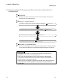
Procedure 1) Register process control tags to be used for MELSEC PX Tag Select. (
Procedure 2) Set the settings to communication with PX Developer by JWDesign. (
Procedure 3) Set process control tags to be monitored on JWEdit. (
Section 3.3.1)
Section 3.3.2)
Section 3.3.3)
Execution on JoyWatcherSuite
The process control tag data can be read/written by executing JWPanel after
starting the monitor tool.
< Example of JoyWatcherSuite operating environment screen >
3-3
3-3
3 BASIC OPERATION
MELSOFT
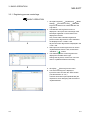
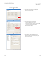
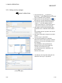
3.3.1 Registering process control tags
BASIC OPERATION
1. Click [All Programs]
[JoyWatcher]
[Basic
[Connection Tools]
[MELSEC
Setting]
PX] from the start menu to start MELSEC PX
Tag Select.
2. The MELSEC PX Tag Select screen is
displayed. A list of process control tags of PX
Developer registered on the monitor tool is
displayed in the tree.
Only current value collection targets and
process control tag items for event notification
are displayed in the <<Main>> tab.
All process control tag items are displayed in the
<<All>> tab.
3. Select process control tag items to be used in
JoyWatcherSuite from the tree, and click the
) button.
"Add Row" (
4. The selected process control tag items are
displayed in the table at the right.
Change the tag name, comment or unit to be
used in JoyWatcherSuite as necessary.
[Save As] from the menu.
5. Click [File]
6. The Save As dialog box is displayed.
Input a file name and click the "Save" button.
(The file extension is ".txt".)
The files saved at this point (defined files) are
required for server designing and execution of
JoyWatcherSuite.
3-4
3-4
3 BASIC OPERATION
MELSOFT
POINT
• Since the maximum number of characters for a JoyWatcherSuite tag name is 64,
a long process control tag name set in PX Developer is indicated in 46 characters
and a serial number (5 digits).
• Characters that cannot be used for process tag name in JoyWatcherSuite are
replaced with the character applicable to JoyWatcherSuite. ("::", ".", "[", "]", "’" are
replaced with "_".)
• The MELSEC PX tag selection function refers tag information from setting data of
the monitor tool. PX Developer tags to be referred are tag FBs (process control
tags) of all supported projects registered in the monitor target project setting of
the monitor tool.
• Even when the information of PX Developer project tag FB is changed and
compiled again after starting the MELSEC PX tag selection function, it is not
reflected to the process control tag list on MELSEC PX tag selection. Read the
project with PX Developer monitor tool again, save the set data, and restart the
MELSEC PX tag selection function.
• If the tag list is not displayed, the following are the possible causes.
(1) The setting data file in the monitor tool is one of the old versions.
(2) A setting not supported by the monitor tool of the versions concerned is
included in the setting data file of the monitor tool.
As each countermeasure, perform the followings:
(1) Refer to "Version Compatibility" in "PX Developer Operating Manual (Monitor
Tool)" and convert the setting data file.
(2) Refer to "Version Compatibility" in "PX Developer Operating Manual (Monitor
Tool)" and check the supportability of the setting data file.
*1: For checking whether the project is supported, refer to "Monitor Target Project
Setting" in "PX Developer Operating Manual (Monitor Tool)".
3-5
3-5
3 BASIC OPERATION
MELSOFT
3.3.2 Server design
BASIC OPERATION
1. Click [All Programs]
[JoyWatcher]
[Basic
[JWDesign] from the start menu to
Setting]
start JWDesign.
2. The JWDesign screen is displayed.
[New] from the menu.
Click [File]
3. The New Database dialog box is displayed.
Input a file name and click the "Save" button.
4. A new database is created.
Right-click [IO] in the tree, and click [New] from
the menu.
(To the next page)
3-6
3-6
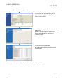
3 BASIC OPERATION
MELSOFT
(From the previous page)
5. The Drivers dialog box is displayed.
Select [MELSEC]
[PX Developer]
Developer], and click the "OK" button.
[PX
6. The driver definition dialog box is displayed.
• Input a name and note.
• When using the virtual PLC mode, check the
"IO Emulation" check box.
Click the "OK" button.
7. A driver is created under [IO] in the tree.
Right-click the created driver ("PX_DRIVER"
for this example), and click "New" from the
menu.
8. The device area setting dialog box is
displayed.
• Input a name and note.
• Input a sampling interval.
).
• Click the 'file selection' button (
(To the next page)
3-7
3-7
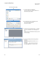
3 BASIC OPERATION
MELSOFT
(From the previous page)
9. The Open dialog box is displayed.
Select the defined file created in Section 3.3.1,
and click the "Open" button.
10. The selected file name is displayed on the
device area setting dialog box.
Click the "OK" button.
[created
11. A device area is created under [IO]
driver ("PX_DRIVER" for this example)] in the
tree.
Double-click the created device area ("PX_TAG"
for this example).
12. A screen for setting device area tag name is
displayed.
Check the tag registered in Section 3.3.1 is
displayed.
[Use server] from the menu.
Click [File]
[SaveAs…] from the menu.
Click [File]
3-8
3-8
3 BASIC OPERATION
MELSOFT
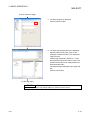
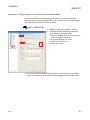
3.3.3 Referring to and selecting process control tags
BASIC OPERATION
1. Click [All Programs]
[JoyWatcher]
[JWEdit] from the start menu to start
[Editor]
JWEdit.
2. The JoyWEdit screen is displayed.
).
Click the "Text" button (
3. Place the text object on the process view, and
double-click it.
4. The Object property dialog box is displayed.
• Check the "Enable" check box in the text
property.
[Direct] in the tree.
• Click [Text]
(To the next page)
3-9
3-9
3 BASIC OPERATION
MELSOFT
(From the previous page)
5. The Direct property is displayed.
Click the "Select" button.
6. The Input Tag setting dialog box is displayed.
Select the device area ("PX_TAG" for this
example) created in Section 3.3.2 under [PLC
Tag] in the tree
Click the tag registered in Section 3.3.1 from
the tag selection list at the bottom center, and
double-click the item to be displayed from the
list at the bottom right.
The selected tag is displayed in the upper edit
box.
Click the "OK" button.
(To the next page)
POINT
When using the Input Tag setting dialog box, start the server control.
3-10
3-10
3 BASIC OPERATION
MELSOFT
(From the previous page)
7. The data set on the Input Tag setting dialog box
are reflected on the Object property dialog box.
Click the "OK" button.
3-11
3-11
3 BASIC OPERATION
MELSOFT
3.4 Operation to Use Faceplates of PX Developer in JoyWatcherSuite
PURPOSE
Use faceplate control of PX Developer for developing process control monitor
screens on JoyWatcherSuite to reduce development time.
Setting on JoyWatcherSuite
Procedure 1) Paste a faceplate control and configure its setting. (
Procedure 2) Set showing faceplate from the object. (
Section 3.4.1)
Section 3.4.2)
Execution on JoyWatcherSuite
By executing JWPanel after starting the monitor tool, faceplates can be used,
process control data can be monitored, and process control parameters can be
tuned.
< Example of JoyWatcherSuite operating environment screen >
3-12
3-12
3 BASIC OPERATION
MELSOFT
3.4.1 Pasting/setting faceplate control
BASIC OPERATION
[JoyWatcher]
1. Click [All Programs]
[JWEdit] from the start menu to start
[Editor]
JWEdit.
2. The JoyWEdit screen is displayed.
).
Click the "MELSEC FP" button (
3. Place the faceplate object on the process view
and double-click it.
4. The object property dialog box is displayed.
Click [MELSEC FP] in the tree, and set the PX
Developer process control tag in the [PX TAG]
column.
Click the "OK" button.
3-13
3-13
3 BASIC OPERATION
MELSOFT
POINT
• When the same process control tag name exists in different projects, specify the
tag as (project name) :: (process control tag name). If the tag is not specified in
such format, the process tag in a project with a high priority becomes an access
target.
• Faceplate control can be used on a personal computer in which PX Developer is
installed and the monitor tool is being started.
3-14
3-14
3 BASIC OPERATION
MELSOFT
3.4.2 Setting of showing faceplate from object
BASIC OPERATION
[JoyWatcher]
1. Click [All Programs]
[JWEdit] from the start menu to start
[Editor]
JWEdit.
2. The JoyWEdit screen is displayed.
).
Click the "Text" button (
3. Place the text object on the process view, and
double-click it.
4. The Object property dialog box is displayed.
[Left] in the tree.
• Click [Mouse]
• Check the "Enable" check box, and the
"Event" check box under "Event".
• Click the 'setting' button under "Event".
(To the next page)
3-15
3-15
3 BASIC OPERATION
MELSOFT
(From the previous page)
5. The Click action dialog box is displayed.
Click the "to Suite" button.
6. The Suite dialog box is displayed.
• Click the "MELSEC FP" button.
• Set the PX Developer process controller tag
name in the edit box at the bottom.
Click the "Finish" button.
7. The settings in the Suite dialog box are
reflected on the Object property dialog box.
Click the "OK" button.
3-16
3-16
3 BASIC OPERATION
MELSOFT
POINT
• When the same process control tag name exists in different projects, specify the
tag as (project name) :: (process control tag name). If the tag is not specified in
such format, the process tag in a project with a high priority becomes an access
target.
• "MELSEC FP" can be used on a personal computer in which PX Developer is
installed and the monitor tool is being started.
• The operation of MELSEC FP displayed on the preview of JWEdit is invalidated.
Use JWPanel to check the operation.
3-17
3-17
3 BASIC OPERATION
MELSOFT
3.5 Operation to Display PX Developer Alarm/Event Information on Alarm Monitor of
JoyWatcherSuite
PURPOSE
Display and monitor alarms and events of the PX Developer monitor tool on
Alarm Monitor of JoyWatcherSuite.
Setting on JoyWatcherSuite
Procedure 1) Configure the data base settings on JWDesign. (
Procedure 2) Set common memory devices on JWDesign. (
Procedure 3) Set the security manager. (
Procedure 4) Set the alarm monitor. (
Section 3.5.1)
Section 3.5.2)
Section 3.5.3)
Section 3.5.4)
Execution on JoyWatcherSuite
Alarms of PX Developer can be monitored on Alarm Monitor of JoyWatcherSuite,
by executing Alarm Monitor of JoyWatcherSuite after starting the monitor tool.
POINT
• Only alarms and events occurred during the execution of monitor tool are
displayed on Alarm Monitor of JoyWatcherSuite.
• The monitor tool and operations (verify, delete) relevant to alarms/events
managed by JoyWatcherSuite are not interacted. Perform the verification of
alarms/events on JoyWatcherSuite side.
• When "Auto ack" is checked on the security manager setting, the alarm/event in
the monitor tool is checked regardless of authority of users who operate the
monitor tool.
3-18
3-18
3 BASIC OPERATION
MELSOFT
The following shows interaction operation of alarms and events.
(1) Operating alarm monitor screen
The following is an alarm monitor screen of JoyWatcherSuite.
< Example of alarm monitor screen of JoyWatcherSuite >
Alarm Monitor of JoyWatcherSuite receives event notifications from the monitor
tool and displays them.
POINT
For the correspondence table of alarm items notified by the monitor tool to
JoyWatcherSuite, refer to Appendix 3.1.
3-19
3-19
3 BASIC OPERATION
MELSOFT
(2) Operating event monitor screen
The following is an alarm monitor screen of JoyWatcherSuite.
< Example of alarm monitor screen of JoyWatcherSuite >
JoyWatcherSuite receives event notifications from the monitor tool and displays
them.
POINT
For the correspondence table of event items notified by the monitor tool to
JoyWatcherSuite, refer to Appendix 3.2.
3-20
3-20
3 BASIC OPERATION
MELSOFT
3.5.1 Configuring database settings
BASIC OPERATION
[JoyWatcher]
[Basic
1. Click [All Programs]
[JWDesign] from the start menu to
Setting]
start the server design.
2. The JWDesign screen is displayed
[Database] from the menu.
Click [Setting]
3. The External database basis setting dialog box
is displayed.
• Input a server name.
• Input " * " for the data source name.
• Click the "Create JWDB" button.
Click the "OK" button.
4. Click [File]
3-21
[SaveAs…] from the menu.
3-21
3 BASIC OPERATION
MELSOFT
3.5.2 Server design
BASIC OPERATION
[JoyWatcher]
[Basic
1. Click [All Programs]
[JWDesign] from the start menu to
Setting]
start the server design.
2. The JWDesign screen is displayed
Right-click [IO] in the tree, and click [New] from
the menu.
3. The Drivers dialog box is displayed.
[Virtual PLC]
Select [JT Engineering]
[Common memory], and click the "OK" button.
4. The Common memory Device dialog box is
displayed
Input a connection name and note, and click
the "OK" button.
(To the next page)
3-22
3-22
3 BASIC OPERATION
MELSOFT
(From the previous page)
5. A common memory is created under [IO] in the
tree.
Right-click the created common memory
("SHARED" for this example), and click [New]
from the menu.
6. The Common memory Device Setting dialog
box is displayed.
• Input a connection name and note.
• Input "2" for "WORD Device".
Click the "OK" Button.
7. A common memory device is created under [IO]
[created common memory ("SHARED" for
this example)].
Select the created common memory device
("SHARED_PX" for this example), and doubleclick it.
(To the next page)
3-23
3-23
3 BASIC OPERATION
MELSOFT
(From the previous page)
8. A screen for setting device area tag name is
displayed.
[SaveAs…] in the menu.
Click [File]
The created common memory device is used
for the security manager setting in Section 3.5.3
and the alarm monitor setting in Section 3.5.4.
3-24
3-24
3 BASIC OPERATION
MELSOFT
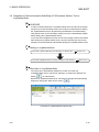
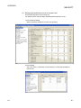
3.5.3 Setting security manager
BASIC OPERATION
[JoyWatcher]
1. Click [All Programs]
[SecurityManager] from the start
[Execution]
menu to start the security manager.
) in
2. Right-click the security manager icon (
the task tray, and click [setUp] from the menu.
3. The Security manager screen is displayed
• Select " * " from the database list box.
• Input a user name for a connection and if a
password is required, input a password.
4. Set a table to store the PX Developer alarm
information in the <<MELSEC PX ALARM>>
tab.
Input a table name for Log table, and click the
"Create" button.
5. Set a tag to notify alarm changes to the alarm
monitor.
Click the "Log Inc Tag" button.
6. The Tag select dialog box is displayed.
Select the common memory device created in
Section 3.5.2 in the tree. ("SHARED_PX" for
this example)
Click "WORD0" in the tag selection list
displayed in the center, and double-click
"VALUE" from the list on the right.
The selected tag name is displayed in the
above edit box.
Click the "OK" button.
7. The settings in the Tag select dialog box are
reflected on the Log Inc Tag edit box.
(To the next page)
3-25
3-25
3 BASIC OPERATION
MELSOFT
(From the previous page)
8. Set a table to store the PX Developer event
information in the <<MELSEC PX Event>> tab.
Input a table name for Log table, and click the
"Create" button.
9. Set a tag to notify event changes to the alarm
monitor.
Click the "Log Inc Tag" button.
10. The Tag select dialog box is displayed.
Select the common memory device created in
Section 3.5.2 in the tree. ("SHARED_PX" for
this example)
Click "WORD1" in the tag selection list
displayed in the center, and double-click
"VALUE" from the list on the right.
The selected tag name is displayed in the
above edit box.
Click the "OK" button.
11. The settings in the Tag select dialog box are
reflected on the Log Inc Tag edit box.
12. For setting other items, refer to the next page.
13. Click the "OK" button.
POINT
• To create a log table, start the server control.
• To use the Tag select dialog box, start the server control.
• To operate with the monitor toolbar, check the "Auto ack" check box in each tab.
3-26
3-26
3 BASIC OPERATION
MELSOFT
DISPLAY/SETTING SCREEN
1)
2)
3)
4)
5)
6)
7)
8)
<<MELSEC PX ALARM>> tab
<<MELSEC PX Event>> tab
DISPLAY/SETTING DATA
No.
Item
Description
1)
Database list box
Select a database to store alarms/events of PX Developer.
2)
Notification delay edit box
3)
Log table list box
4)
Delete Log edit box
5)
Log Inc Tag edit box
6)
Server ID edit box
Set an interval of time until changed tags are incremented after data are
stored to database.
Set a table to store alarms/events of PX Developer.
*1
The created log table is used for the alarm monitor setting in Section 3.5.4.
Set a number of days to keep the logs.
When "0" is set, logs are not deleted.
Set a tag (common memory device created in Section 3.5.2) to notify
alarm/event changes to the alarm monitor.
*2, *3
Set an ID to identify the function storing order when data are stored to the
database.
When a file name is specified, obtain all alarms/events from the monitor tool
at the security manager start, and alarms/events which are not notified to the
7)
Conversion file
security manager are also stored to the database.
*4
When a file name is not specified, only alarms/events which occurred during
the security manager start are stored to the database.
Check this to confirm PX Developer side alarms/events at the moment when
8)
Auto ack checkbox
data are stored to the database of JoyWatcherSuite. (The alarm/event row is
not displayed in the monitor tool bar.)
*1: Set tables with a different name for alarms and events.
*2: Set the same tag with the "JoyWatcher Tag Change" tag of the alarm monitor auto update
setting.
*3: Set tags with a different name for alarms and events.
*4: Set files with a different name for alarms and events.
3-27
3-27
3 BASIC OPERATION
MELSOFT
POINT
• For operations of alarms/events, it is recommended that the "Auto ack" check box
is checked and Alarm Monitor of JoyWatcherSuite is used.
• For alarms whose occurrence status is "information" (alarms whose recovery
date is not displayed), the automatic confirmation is not performed to prevent
frequent alarm occurrence even when the "Auto ack" check box is checked.
When an alarm whose occurrence status is "information" is occurred, check the
alarm on the alarm screen of the monitor tool after fixing the problem that caused
the alarm.
3-28
3-28
3 BASIC OPERATION
MELSOFT
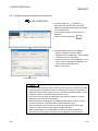
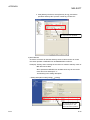
3.5.4 Setting alarm monitor
BASIC OPERATION
[JoyWatcher]
1. Click [All Programs]
[EvGridMon] from the start menu to
[Editor]
start the alarm monitor.
2. The AlarmMonitor screen is displayed.
)
Click the "Config" button. (
3. The Database screen of the Config dialog box
is displayed
• Input " * " for DSN under Database.
• Select "EventSummary/MELSEC PX Alarm"
for Data type.
• Check the "JoyWatcher Tag" check box.
)
• Click the 'tag select' button. (
4. The Tag Select dialog box is displayed.
Select the common memory device created in
Section 3.5.2 in the tree. ("SHARED_PX" for
this example)
Click the same tag set for Log Inc Tag in the
<<MELSEC PX ALARM>> of security manager
("WORD0" for this example) in the tag selection
list displayed in the center, and double-click
"VALUE" from the list on the right.
The selected tag name is displayed in the
above edit box.
Click the "OK" button.
(To the next page)
POINT
To use the Tag select dialog box, start the server control.
3-29
3-29
3 BASIC OPERATION
MELSOFT
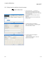
(From the previous page)
5. The settings in the Tag select dialog box are
reflected on the JoyWatcher Tag edit box.
Click the "Next >" button.
6. The EventSummary/MELSEC PX Alarm screen
is displayed.
Select the log table created in Section 3.5.3
from the data table list box, and click the
"Generate" button.
7. The Column screen is displayed.
Set details of the displayed items and click the
"Finish" button.
Configure the settings for data type "MELSEC PX Event" with the same procedure.
3-30
3-30
3 BASIC OPERATION
MELSOFT
POINT
The following shows the setting example to arrange the display as same as the
monitor tool.
3-31
3-31
3 BASIC OPERATION
MELSOFT
3.6 Operation to Perform Interactive Start/Stop of PX Developer Monitor Tool on
JoyWatcherSuite
PURPOSE
In order to interact between the JoyWatcherSuite server and the PX Developer
monitor tool, the PX Developer monitor tool needs to be started before starting
the JoyWatcherSuite server. By performing the MELSEC PX interact setting
using JWLauncher, the PX developer monitor tool can be automatically started
before starting the JoyWatcherSuite server.
To use the alarm integration function, the security manager needs to be started
after starting the JoyWatcherSuite server. By using JWLauncher, the security
manager can be automatically started after starting the JoyWatcherSuite server.
Setting on JoyWatcherSuite
Procedure 1) Set the MELSEC PX interaction on JWLauncher. (
Procedure 2) Register tasks of security manager on JWLauncher. (
Section 3.6.1)
Section 3.6.2)
Execution on JoyWatcherSuite
The functions are automatically started in the order of monitor tool,
JoyWatcherSuite server, and security manager, by clicking the "Start Server"
) on JWLauncher.
button (
Monitor tool, JoyWatcherSuite server, and security manager are automatically
stopped by clicking the "Stop Server" button (
).
< Example of JoyWatcherSuite JWLauncher >
3-32
3-32
3 BASIC OPERATION
MELSOFT
3.6.1 Setting interactive start/stop of monitor tool
BASIC OPERATION
[JoyWatcher]
1. Click [All Programs]
[Execution] from the start menu and click
[JWLauncher] while holding down the Shift key
to start JWLauncher.
2. The JoyWatcher Suite Launcher screen is
displayed.
Click the "Select JDD" button (
).
3. The ServerMode dialog box is displayed.
• Select LocalServer for Server Mode.
• Specify the server design file (".JDD") created
in Section 3.3.2 for Local Server.
• Check the "Start" and "EndIntegration" check
boxes under Cooperation with MELSEC PX.
• Input a value for Start Wait Time.
Click the "OK" button.
(To Section 3.6.2)
POINT
• To perform interactive stop of the monitor tool, the mode of the monitor tool needs
to be changed to the engineer mode. For changing the mode to the engineering
mode when starting the monitor tool, refer to "Monitor Tool Startup Option" in "PX
Developer Version 1 Operating Manual (Monitor Tool)".
• The monitor tool cannot perform interactive stop when any dialog box is being
displayed. End the monitor tool manually.
• If the monitor tool is restarted while JoyWatcherSuite and the monitor tool are in
an interact operation, JoyWatcherSuite must be restarted as well.
• When the start time of the monitor tool becomes longer because of the large
number of monitor target projects, adjust the Start Wait Time.
• When "EndIntegration" of the MELSEC PX interaction setting is enabled on
JWLauncher, do not register JWLauncher to user graphic of the monitor tool.
3-33
3-33
3 BASIC OPERATION
MELSOFT
3.6.2 Setting interactive start/stop of security manager
BASIC OPERATION
[JoyWatcher]
1. Click [All Programs]
[Execution] from the start menu and click
[JWLauncher] while holding down the Shift key
to start JWLauncher.
2. The JoyWatcher Suite Launcher screen is
displayed.
Right-click "Add Task" and click [NewTask]
from the menu.
3. The setting dialog box is displayed.
Select "SecurityManager" for Start Program,
and click the "Next >" button.
4. The setting dialog box is displayed.
• Select "StartUp".
• Check the "EndIntegration" check box.
Click the "Finish" button.
3-34
3-34
4 TROUBLESHOOTING
MELSOFT
4 TROUBLESHOOTING
(1) Troubleshooting related to the communication function regarding
process control tag names
This section explains troubleshooting for failures possibly occur in relation to the
communication function regarding process control tag names.
Trouble
Cause/corrective action
Reference
The following are the possible factors.
• The monitor tool is not started.
• The JoyWatcherSuite server control is not started.
• The assignment information database, to which the relevant process
control tags are registered, is not registered to the monitor target
project of the monitor tool.
While JWPanel is in
4
• The relevant assignment information database is registered to the
operation, the monitor data
indicates "????????".
monitor target project of the monitor tool after starting the monitor tool
Section 3.1
or JoyWatcherSuite server control.
Check if JWPanel is executed by the following procedure.
1. Start the monitor tool
2. Register/apply the relevant assignment information database to the
monitor target project of the monitor tool.
3. Start the JoyWatcherSuite server control.
4. Start JWPanel.
The following are the possible factors.
• The monitor tool is not started.
• The assignment information database, to which the relevant process
control tag is registered, is not registered to the monitor target project
of the monitor tool.
Although the process control
tag data in PX Developer are
changed while JWPanel is in
operation, the monitor data do
not change.
• The monitor tool is in communication error.
• The user who is operating the monitor tool does not have the authority
of operation for changing the tag data items.
Check and set the following items.
Section 3.1
• Check if the monitor tool is in operation.
• Check if the process control tag exists in the monitor target project of
the monitor tool.
• Check for the communication error from the list of PX Developer
alarms.
• Switch to a user who has the authority of operation for changing the
process control tag data items in the monitor tool.
(2) Troubleshooting related to the incorporation function of faceplate
control
For troubleshooting for failures possibly occur in relation to the incorporation
function of faceplate control, refer to "Error list" in "ActiveX control" section of "PX
Developer Operating Manual (Monitor Tool)".
4-1
4-1
4 TROUBLESHOOTING
MELSOFT
(3) Troubleshooting related to the alarm integration function
This section explains troubleshooting for failures possibly occur in relation to the
alarm integration function.
Trouble
Cause/corrective action
Reference
The monitor tool may not be executed or JoyWatcherSuite may not be
set correctly.
Check the following items.
• Start the monitor tool in advance.
Alarms or events of the
monitor tool are not displayed
on the alarm monitor of
JoyWatcherSuite.
• Check the external database settings in the JoyWatcherSuite server
design.
• Check if a tag used for "Log Inc Tag" is registered to common memory
Section 3.5
Section 3.6
in the JoyWatcherSuite server design.
• The "Log Inc Tag" settings are different between JoyWatcherSuite
server design, security manager, and alarm monitor.
4
• Check the settings of JoyWatcherSuite security manager.
(4) Troubleshooting related to JWEdit
The event operation set on the object cannot be executed on the preview screen
of JWEdit.
Therefore, when executing operation check of event such as "MELSEC FP" and
"ExternalProgram", check with JWPanel.
4-2
4-2
APPENDIX
MELSOFT
APPENDIX
Appendix 1 Data Types of Process Control Tag Items
For lists of tag items of process control tag that can be selected on MELSEC PX tag
selection, refer to "List of Various Tag Type/Tag Data" in "PX Developer Programming
Manual".
The following table shows the data types in JoyWatcherSuite corresponding to the
data types of process control tag item in PX Developer.
Data type in PX Developer
Data type in JoyWatcherSuite
BOOL
BIT
INT
SHORT
DINT
LONG
WORD
USHORT
REAL
SINGLE
Appendix 2 Main Tag Items
Main tag items of process control tag displayed on the MELSEC PX tag selection are
the tag items which perform the current value collection and event notification.
The following table shows the tag items which perform current value collection.
Tag FB name
PID, 2PID, PIDP,
SPI, IPD, BPI, R,
ONF2, ONF3
2PIDH, SWM,
PFC_SF, PFC_SS,
PFC_INT
PGS
PGS2
MOUT
MONI
Current value collection tag
PV
MV
SV
PV
MV
SVC
SV
MV
SV
TYP
SV
STC
T
PV
TYP
SV0C
MV
PV
PV
SVC
PVAL
SV
VOUT
DIM
B-1
Process variable
Manipulated variable
Setting value
Process variable
Manipulated variable
Setting value (current)
Setting value (target)
Manipulated variable
Setting value
Operation type
Setting value
Executing step No.
Time in the step
Process variable
Operation type
Start point (current)
Manipulated variable
Process variable
Motor valve opening
Setting value of valve
opening (current)
Setting value of valve
opening (target)
Tag FB name
MWM
SEL
BC
PSUM
NREV, REV,
MVAL1, MVAL2, PB
TIMER1,
TIMER2,
COUNT1,
COUNT2
ALM, ALM_64PT,
MSG, MSG_64PT
HTCL
Current value collection tag
PV
MV
PV
MV
SLNO
PV
SV1
SV2
SV
PV
Process variable
Manipulated variable
Process variable
Manipulated variable
Selection No.
Process variable
Setting value 1
Setting value 2
Setting value
Process variable
DIM
Monitor input buffer
PV
Process variable
PSV
Setting value
SV
Setting value
DIM
Monitor input buffer
No corresponding current value
collection tags.
MV_HT
Heating manipulated
variable
MV_CL
Cooling manipulated
variable
SV
Setting value
Command signal
output status
Monitor input buffer
B-1
App
APPENDIX
MELSOFT
The following table shows the tag items which perform event notification.
Tag FB name
PID, 2PID, NREV,
REV, MVAL1, MVAL2,
PGS2, HTCL
2PIDH, SWM,
PFC_SF, PFC_SS,
PFC_INT, PVAL
PIDP, SPI, IPD, BPI, R,
ONF2, ONF3, MWM,
SEL, MOUT, PGS
MONI
Event notification tag
*1
MODE
Mode
*1
ALM
Alarm
CTNO
Lookout tag No.
*1
DIM
Monitor input buffer
*1
MODE
Mode
*1
ALM
Alarm
*1
ALM2
Alarm 2
CTNO
Lookout tag No.
*1
DIM
Monitor input buffer
*1
MODE
Mode
*1
ALM
Alarm
CTNO
Lookout tag No.
*1
ALM
Alarm
CTNO
Lookout tag No.
Tag FB name
BC, PSUM,
TIMER1, TIMER2,
COUNT1, COUNT2
PB
ALM
ALM_64PT
MSG
MSG_64PT
Event notification tag
ALM
Alarm
CTNO
Lookout tag No.
*1
DIM
Monitor input buffer
*1
MODE
Mode
CTNO
Lookout tag No.
*1
DIM
Monitor input buffer
*1
ALM
Alarm
*1
ALM_W1
Alarm 1 to 16
*1
ALM_W2
Alarm 17 to 32
*1
ALM_W3
Alarm 33 to 48
*1
ALM_W4
Alarm 49 to 64
*1
MSG
Message
*1
MSG_W1
Message 1 to 16
*1
Message 17 to 32
MSG_W2
*1
MSG_W3
Message 33 to 48
*1
MSG_W4
Message 49 to 64
*1
*1: This tag item consists of multiple BOOL type variables; however, it is displayed as a BOOL type variable on the
App
MELSEC PX tag selection screen.
B-2
B-2
APPENDIX
MELSOFT
Appendix 3 Correspondence Table for Items of Monitor Tool and JoyWatcherSuite
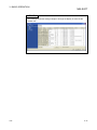
Appendix 3.1
Correspondence table for alarm items
The following is a correspondence table for alarm items notified to JoyWatcherSuite by
the monitor tool.
In the alarm monitor of JoyWatcherSuite, a display name, item, and display format can
be selected in the property.
For details, refer to "JoyWatcherSuite user’s guide".
PX Developer monitor tool
Alarm item
Expression
Alarm monitor of JoyWatcherSuite
Maximum number
Alarm item
Confirm Check
ON/OFF
EV_CONFIRM
Tag
FIC001
EV_POINT
64
EV_CAPTION
64
Tank 1 water
Tag Comment
level
*2
Alarm Contents
Occurrence Date
MHA
The format
-
*2
EV_USERDEF2
Level
Measured Value
64
EV_EDATE
-
depends on the
Recovered Date
Expression
*1
of characters
ON/OFF
"Tag"
Example) FIC001
"Tag Comment"
Example) Tank 1 water level
"Alarm Contents"
Example) MHA
Depends on the setting of date
format in the alarm monitor.
setting of OS.
EV_RDATE
Minor/Major
EV_LEVEL
-
Minor: 1, major: 3
100%
EV_VALUE
64
100%
EV_SID
-
EV_ID
-
Server ID
*3 *4
*3
Serial number
Event status is saved.
No correspondence
E: Occurrence
EV_STATUS
1
EV_CODE
1
"0"
EV_RVALUE
64
"(blank space)"
-
"0"
R: Recovery
C: Information
EV_USERDEF1
*1: Characters that are exceeded the maximum number of characters are not stored to the database.
*2: The description corresponds to "Tag Data Item Display of Alarm" on the option setting of the monitor tool is displayed.
*3: EV_SID is an ID to distinguish programs which are inserted to the same table. EV_SID+EV_ID is a unique ID.
*4: EV_SID is the same as "Server ID" on the Security manager screen.
B-3
B-3
APPENDIX
MELSOFT
Appendix 3.2
Correspondence table for event items
The following is a correspondence table for the event items notified to
JoyWatcherSuite by the monitor tool.
In the alarm monitor of JoyWatcherSuite, a display name, item, and display format can
be selected in the property.
For details, refer to "JoyWatcherSuite user’s guide".
PX Developer monitor tool
Event item
Expression
Confirm Check
ON/OFF
Tag
TIC001
Tank
Tag Comment
temperature
*2
Event Message
SV
Alarm monitor of JoyWatcherSuite
Maximum number
Event item
*1
of characters
No correspondence (State is left blank.)
EV_TagName
64
EV_TagComment
64
*2
EV_Description
64
The format
Occurrence Date
depends on the
EV_DATE
-
setting of OS.
*2
Status
*2
CAS
EV_Mode
Set Value
90.0 ºC
EV_Value
64
User
admin
EV_UserName
64
*2
No correspondence
Expression
*2
64
EV_SID
-
EV_ID
-
"Tag"
Example) TIC001
"Tag Comment"
Example) Tank temperature
"Event Message"
Example) SV
Depends on the setting of date
format in the alarm monitor.
"Status"
Example) CAS
90.0 ºC
"User"
Example) admin
Server ID
*3 *4
*3
Serial number
*1: Characters that are exceeded the maximum number of characters are not stored to the database.
*2: The description corresponds to "Tag Data Item Display of Event" on the option setting of the monitor tool is displayed.
*3: EV_SID is an ID to distinguish programs which are inserted to the same table. EV_SID+EV_ID is a unique ID.
*4: EV_SID is the same as "Server ID" on the Security manager screen.
B-4
B-4
APPENDIX
MELSOFT
Appendix 4 Calling Monitor Tool Function from JoyWatcherSuite
A buzzer of monitor tool can be stopped or specified screen can be displayed by
calling the MonCtrl command (MonCtrl.exe) of the monitor tool from JoyWatcherSuite.
The following shows a setting method on JWEdit.
BASIC OPERATION
1. Double-click the object pasted on JWEdit.
2. The Object property dialog box is displayed.
• Click [Mouse] [Left] in the tree.
• Check the "Enable" check box, and check the
"Event" check box under Event.
• Set "ExternalProgram" for Event.
*1
• Set "MonCtrl.exe" for User.
Click the "OK" button.
*1: For functions that can be specified by the MonCtrl command, refer to "External
Control of the Monitor Tool" in "PX Developer Operating Manual (Monitor Tool)".
B-5
B-5
APPENDIX
MELSOFT
Appendix 5 Security of Monitor Tool and JoyWatcherSuite
The mixture of the user authority function of the monitor tool and the security function
of JoyWatcherSuite enables to set the restrictions for operation of process control tag
on the graphic screen and alarm check of JoyWatcherSuite.
For details of the security function of JoyWatcherSuite, refer to "JoyWatcherSuite
user’s guide".
Appendix 5.1
Operating environment for using security of monitor tool and
JoyWatcherSuite
The following describes the operating environment for using security of the monitor tool
and JoyWatcherSuite.
Application
Appendix 5.2
Version
PX Developer
Version 1.31H or later
JoyWatcherSuite
Version 6.1 or later
Setting procedure for using security of monitor tool and JoyWatcherSuite
The following diagram describes the setting procedure for using the user authority
function in the monitor tool and the security function in JoyWatcherSuite.
Start to set the items.
(1) Set the user authority function in the monitor tool.
(2) Set the security function in JoyWatcherSuite.
(3) Set to change the users of the monitor tool with JoyWatcherSuite.
Completed
B-6
B-6
APPENDIX
MELSOFT
(1) Setting user authority function in monitor tool
Set the following items in the monitor tool.
For details, refer to "PX Developer Operating Manual (Monitor Tool) ".
1) User Authority Setting
Set the operation restrictions for each user authority.
2) User Setting
Set a user name, a password, and the authority of users who operate the
monitor tool.
B-7
B-7
APPENDIX
MELSOFT
(2) Setting security function in JoyWatcherSuite
Set the following items in JoyWatcherSuite.
For details, refer to "JoyWatcherSuite user’s guide".
1) User setting
Set a user name, a password, a role, and the authority of users who operate
JoyWatcherSuite.
When using the security of the monitor tool and JoyWatcherSuite, set the
same user authority description of the monitor tool and that of
JoyWatcherSuite.
The following describes an example of "JWUserDef" of JoyWatcherSuite.
1. Set a name of authority ID on the <<Auth>> tab.
Set the names of item (tag data item change, alarm monitor check) where
the security can be set for operations in JoyWatcherSuite.
Authority ID
B-8
Name
1
MELSEC PX ALARM/EVENT confirm
2
MELSEC PX tag Process instruction values/Mode
3
MELSEC PX tag Alarm threshold values
4
MELSEC PX tag Tuning parameter values
5
MELSEC PX tag Process design values
6
MELSEC PX tag exclusive to engineer
B-8
APPENDIX
MELSOFT
2. Set a role name and an authority number on the <<Role>> tab.
Set the user authority (Engineer, Operator1 to 4) and the authority ID of the
monitor tool.
Role ID
Role name
1
Engineer
2
Operator4
3
Operator3
4
Operator2
5
Operator1
Authority ID
1
2
3
4
5
6
: Operation permitted, : Operation prohibited
Set the authority ID which permits
the operations for each role.
B-9
B-9
APPENDIX
MELSOFT
3. Set a user name, a password, and a role on the <<User>> tab.
Set the same user name, password, and role as the user setting in the
monitor tool.
User setting of the monitor tool
User name
User authority
User setting of JoyWatcherSuite
User name
Role
admin
Engineer
admin
1
User04
Operator4
User04
2
User03
Operator3
User03
3
User02
Operator2
User02
4
User01
Operator1
User01
5
Set a role for each user.
POINT
• The authority which corresponds to the lock mode of the monitor tool is the
GUEST mode in JoyWatcherSuite. The GUEST mode is the status of execution
of log in operation with the GUEST mode or that of log off operation.
• Set the same user name and password on the user setting of the monitor tool and
JoyWatcherSuite.
B-10
B-10
APPENDIX
MELSOFT
2) JWEdit
As security when writing numerical values to the process control tag items,
check the "Enable" check box of Object property, and set the "authority ID"
required for operations to control valid/invalid of mouse operation.
Example) Security when writing numerical values to "TIC001.PH" which is PV
high limit alarm value of process control tag TIC001.
Since the operation classification of process control tag "TIC001.PH"
is alarm threshold value, only role ID users which have authority ID
"3" can execute the operations.
The following diagram describes the setting procedure.
1. Double click the object for writing numerical value, or right-click
the context menu, and select [Property].
2. Click [Mouse] [Left Button] of left tree, and set the numerical
value writing to process control tag "TIC001.PH" on [Write to].
Valid the left-button operation.
Execute the setting to write
the numerical value to
TIC001.PH.
B-11
B-11
APPENDIX
MELSOFT
3. Click [Mouse] of left tree, select [Security & Log], and set the
operation authority ID to process control tag "TIC001.PH".
Valid security, and set the authority
ID required for the operations.
3) Alarm Monitor
Check the check box to valid the authority check of alarm monitor to control
the check operation of MELSEC PX ALARM/MELSEC PX Event.
Example) Security when checking the check box to valid the authority check of
MELSEC PX ALARM
Set to operate the MELSEC PX ALARM check only for the role ID
users who have authority ID "1".
The following is the setting description.
• Setting description under [Config]
[Config].
Only the role ID users who
have authority ID "1" can
execute the check operation.
B-12
B-12
APPENDIX
MELSOFT
(3) Setting to change users of monitor tool with JoyWatcherSuite
1) JWPanel
For changing the users of the monitor tool with JoyWatcherSuite, check the
check box of "MELSEC PX User" on the security setting of JWPanel. This
enables to change the modes of the monitor tool automatically when logging in
JoyWatcherSuite, or switching users.
Note that the mode to be changed in the monitor tool in this regard is changed
to a mode of user who has the same user name and password entered when
logging in JoyWatcherSuite or switching users is the same.
When logging in or logging off with the GUEST mode in JoyWatcherSuite, the
mode in the monitor tool is changed to the lock mode.
• Setting description under [Security]
[Setting…]
Check the check box of MELSEC
PX User to change the modes of
the monitor tool when logging in, or
switching users.
Appendix 5.3
Procedure for monitoring operation with security interaction between
monitor tool and JoyWatcherSuite
When monitoring with security interaction between the monitor tool and
JoyWatcherSuite, monitor by following the procedure described below.
1) Start the monitor tool and JoyWatcherSuite server with JoyWatcherSuite
JWLauncher.
2) Start JoyWatcherSuite JWPanel.
3) Switch the users with JoyWatcherSuite.
POINT
When an error message is displayed with the monitor tool by changing login users
with JoyWatcherSuite, log in with the GUEST mode which does not have the
authority with JoyWatcherSuite once, or log off, and log in with the operation user
again after the problem is solved.
B-13
B-13
APPENDIX
MELSOFT
Appendix 6 Functions Added to and Changed from Old Version
The following table indicates the functions added and changed with the upgrade.
Compatible
1
version*
Version 1.42U
Added/changed
function
Supported OS
Description
R
Windows 8 is supported.
Reference
Section 2.3
*1: The compatible version can be confirmed in Product Information. For details, refer to the "PX Developer Operating
Manual (Programming Tool or Monitor Tool)".
B-14
B-14
APPENDIX
MELSOFT
MEMO
B-15
B-15
INDEX
Ind
[A]
Alarm integration function ........................... 1-1, 5
Alarm Monitor ................................................A-10
Assignment information database ................A-11
[C]
Calling Monitor Tool Function from
JoyWatcherSuite ............................................. B-5
Communication function using process control tag
names .......................................................... 1-1, 3
Configuring database settings ...................... 3-21
Correspondence table for alarm items ........... B-3
Correspondence table for event items ........... B-4
Correspondence Table for Items of Monitor Tool
and JoyWatcherSuite ...................................... B-3
[D]
Data Types of Process Control Tag Items
......................................................................... B-1
DDC ...............................................................A-10
DDE ...............................................................A-10
[F]
Faceplate .......................................................A-11
FB ..................................................................A-10
FBD................................................................A-10
[I]
Incorporating faceplate control ................... 1-1, 2
[J]
JoyWatcherSuite ...........................................A-10
JWDesign ........................................ A-10, 3-6, 22
JWEdit ...........................................................A-10
JWLauncher ..................................................A-10
JWPanel ........................................................A-10
[O]
Operating alarm monitor screen....................3-19
Operating event monitor screen....................3-20
Operating Environment....................................2-4
Operating Procedures for Monitoring on
JoyWatcherSuite..............................................3-1
Operation to Communicate using Process Control
Tag Names of PX Developer in JoyWatcherSuite
..........................................................................3-3
Operation to Display PX Developer Alarm/Event
Information on Alarm Monitor of JoyWatcherSuite
........................................................................3-18
Operation to Perform Interactive Start/Stop of PX
Developer Monitor Tool on JoyWatcherSuite ......
........................................................................3-32
Operation to Set PX Developer Projects to be
Monitored on Monitor Tool...............................3-2
Operation to Use Faceplates of PX Developer in
JoyWatcherSuite............................................3-12
[P]
Pasting/setting faceplate control ...................3-13
Personal computer........................................ A-10
Process control tag ....................................... A-10
Process control tag data............................... A-10
Process control tag data item....................... A-10
Programming tool.......................................... A-10
PV.................................................................. A-11
PX Developer ................................................ A-10
[R]
Reference function for PX Developer process
control tag names ........................................1-1, 4
Referring/selecting process control tags.........3-9
Registering process control tags .....................3-4
[S]
[M]
Main Tag Items................................................ B-1
MELSEC PX Tag Select ...............................A-10
Monitor tool....................................................A-10
MV..................................................................A-11
C-1
Security of Monitor Tool and JoyWatcherSuite
......................................................................... B-6
Security Manager.......................................... A-10
Setting alarm monitor.....................................3-29
Setting interactive start/stop of monitor tool
........................................................................3-33
Setting interactive start/stop of security manager
........................................................................3-34
C-1
Setting of showing faceplate from object...... 3-15
Setting monitor target projects........................ 3-2
Setting security manager .............................. 3-25
Software Configuration.................................... 2-3
SV ..................................................................A-11
SYSTEM CONFIGURATION.......................... 2-1
Ind
[T]
Tag FB ...........................................................A-11
TROUBLESHOOTING.................................... 4-1
Troubleshooting related to the communication
function regarding process control tag names
......................................................................... 4-1
Troubleshooting related to the alarm integration
function ............................................................ 4-2
C-2
C-2
Windows is a registered trademark or registered trademark of Microsoft Corporation in the United States and other
countries.
JoyWatcherSuite is a trademark or registered trademark of JT Engineering inc.
All other company names and product names used in this manual are trademarks or registered trademarks of their
respective companies.
SH(NA)-080976ENG-D(1507)KWIX
MODEL:SW1D5C-FBDQ-O-JYWS-E
MODEL CODE: 13JU70
HEAD OFFICE : TOKYO BUILDING, 2-7-3 MARUNOUCHI, CHIYODA-KU, TOKYO 100-8310, JAPAN
NAGOYA WORKS : 1-14 , YADA-MINAMI 5-CHOME , HIGASHI-KU, NAGOYA , JAPAN
When exported from Japan, this manual does not require application to the
Ministry of Economy, Trade and Industry for service transaction permission.
Specifications subject to change without notice.