1
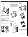
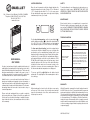
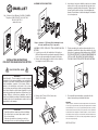
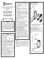
180, 3e Avenue, LʼIslet (Québec) G0R 2C0 CANADA
Telephone: (418) 247-3947, 1 800 463-7043
Fax: (418) 247-7801
www.ouellet.com
INSTALLATION INSTRUCTIONS
for Bathroom Heater «OHY Series»
INSTALLATION MUST BE ACCOMPLISHED
BY A QUALIFIED TECHNICIAN
RISK OF ELECTRIC SHOCK
WARNING
Read Carefully - These instructions contain necessary
information for the proper installation, use and efficient
operation of the heater. Carefully read these instructions
before installation, operation of the heater. Failure to
adhere to the instructions could result in fire, electric
shock, serious personal injury, death or property damage.
Save these instructions and review frequently for continuing safe operation and instruction of future users, if necessary.
1.
2.
3.
4.
5.
6.
ATTENTION
Carefully read these instructions before installation.
Never paint the heater.
Never alter the heater.
Never install the heater on a wall covered with vinyl.
Do not use outdoors.
This heater may become hot when in use. To avoid
burns, do not touch hot surfaces of the heater with
bare skin. Keep all combustible materials away from
top and front of heater: furniture, pillows, bedding,
paper, clothing, bath towel, bath robe, drapes, etc.
7. Heater should not be blocked in any manner.
8. Install heater in position shown in installation figures
of these instructions.
9. Allow 102 mm (4 in) minimum clearance below heater.
10. Allow 25 mm (1 in) minimum clearance between sides
of heater and any adjacent walls.
11. Allow 1219 mm (48 in) minimum in front of heater.
12. Extreme caution is necessary when any heater is
used by or near children or invalids and whenever the
heater is left operating and unattended.
13. Use intended holes in enclosure to secure heater
in place as specified in these instructions.
14. To avoid electric shock disconnect all power to heater
at the main service panel before installation, wiring
or servicing and replace front cover of heater before
putting the power back.
15. Use power supply wire suitable for at least 90 °C
(194 °F).
16. All wiring must be done in accordance with the
national and local electrical codes and the heater must
be grounded.
17. A incorrectly installed heater may be permanently
damaged and present a risk of fire or electric shock.
Required minimal clearances must be observed along
with theses instructions. Heater must be tightly fixed to
the buildingʼs framing.
18. Do not install heater in vapor or shower bathrooms nor
in places where it will be exposed to a high level of
humidity or vapor for a long period.
19. Make sure applied voltage is suitable for rating
of heater.
20. Dot not insert or allow foreign objects to enter any
ventilation opening as this may cause electric shock,
short circuit, fire or damage to heater.
21. Do not block air inlet or outlet in any manner.
22. Use heater only as described in the USER GUIDE
provided with these instructions. Any other use not
recommended by the manufacturer may cause fire,
electric shock or injury to persons.
23. Refer to the USER GUIDE for servicing
and troubleshooting tips on this heater.
24. AMERICAN VERSION ONLY: This heater includes
a visual alarm (red light) to warn parts of the heater
are getting excessively hot. If the light turns on
immediately turn the heater off and inspect for any
objects on or adjacent to the heater that may cause
high temperatures. If nothing seems to obstruct air
inlet, have heater inspected by a qualified person. DO
NOT OPERATE THE HEATER WITH THE ALARM
LIGHT ON.
SURFACE WALL MOUNTING
(WITH OR WITHOUT OHY-CM):
12" (305 mm)
Recommandé
4" (102 mm)
Minimum
Keep a clearance of 1219 mm (48 in) minimum in front
of heater and 25 mm (1 in) to any walls.
SURFACE WALL MOUNTING STEPS:
1. To install the optional cast trim sleeve, refer to instructions
provided with option OHY-CM. Heater may be surface
mounted without the optional cast trim sleeve.
Recommended installation height is 305 mm (12 in) below
heater. Use provided template to locate positioning of the
supply wire.
WARRANTY
Ouellet Canada Inc. warrants the electric heating element of the OHY Series
for a five (5) year period and the component parts against defects in material
and workmanship for a two (2) year period following the date of purchase,
under normal use and service, when proof of purchase of such is provided to
the manufacturer. The obligation of Ouellet Canada Inc., under the terms of
this warranty, will be to supply a new unit and this omits the manufacturer to
bear the installation costs or other secondary charges linked to replacing the
unit or the component part(s).
2. Follow steps #2 to #11 of RECESSED WALL MOUNTING.
Pat. No. Des. D571,906 S
RECESSED WALL MOUNTING:
2 3/4" (70 mm)
5. Use the appropriate knock-out hole (KOE 7/8 in) within the
junction box as well as the 6.35 mm (1/4 in.) knock-outs (item A
in the figure) located on each side of enclosure that will be used
to fix it to the wall. Run the power cable inside the enclosure.
6. Fix the enclosure by using the 6.35 mm (1/4 in.) knock-outs or
the holes on the back (indicated as item B in the figure) to firmly
fix the heater with provided screws (two additional longer screws
are provided to help in case of larger framing). DO NOT FIX THE
HEATER WITH THE HOLES MENTIONNED IN STEP #4 USED
TO SCREW THE INSIDE MODULE; THIS MAY CAUSE THE
HEATER TO MALFUNCTION.
9. Replace junction box cover and remove the front cover
from its protective bag.
10. Fix the plastic connector on the outlet located in the top
of the front cover.
A
C
B
12" (305 mm)
Recommended
4" (102 mm)
Minimum
A
C
B
Keep a clearance of 1219 mm (48 in.) minimum in front
of heater and 25 mm (1 in.) to any walls.
KOE Ø7/8”
7. Put inside module back and tighten the four (4) RED screws.
8. Wire the heater according to national and local codes and along
instructions marked on heater.
P2/N
L2/N
P1
Option
Disconnect
L1
M
OHY1502/2000
OHYU1502/2000
Load 2
Load 1
P2/N
FAN2
COM
LOAD1
LOAD2
FAN1
RECESSED WALL MOUNTING STEPS:
1. Make a hole within the wall at least 70 mm (2 3/4 in.) of depth.
The hole must be 473 mm (18 5/8 in.) by 340 mm (13 3/8 in.);
use the template provided with the heater. CAUTION: HOLE
MUST BE CUT PRECISELY.
2. Remove front cover by unscrewing both screws at the bottom.
3. Remove the junction box cover by unscrewing the screw. Note
the plastic connector secured inside the junction box will be
connected outside the box once the heater is fully installed.
This connector links the enclosure with the display located on
the front cover.
4. Remove the inside module to which the fan is fixed
by loosening the four (4) RED screws.
Hi-Limit
250 °F
121 °C
Load 2 = 1000W (240V), 500W (120V)
Load 1 = 1000W (240V), 1000W (120V)
OHYU only
Power Base
P1
11. Put front cover back making sure the cable linking the cover
with the heater does not get stuck. Test the heater to insure
control works properly.
Keep this instruction pamphlet for the user.
INS101-200702-00
180, 3e Avenue, L’Islet (Québec) G0R 2C0 CANADA
Telephone: (418) 247-3947, 1 800 463-7043
Fax: (418) 247-7801
www.ouellet.com
HEATER OPERATION
SAFETY
Once the unit is powered up the blue display indicates the
ambient temperature in degree Celsius (°C) or Fahrenheit
(°F). To change the units from °C to °F or vice versa, press
the two buttons with arrow signs on the right side of display
simultaneously for two (2) seconds.
To avoid problems do not allow water in and make sure no
splash get inside heater. IMPORTANT: DO NOT USE
HEATER AS A TOWEL DRYER. DO NOT COVER HEATER
WHEN POWERED ON.
MAINTENANCE
Clean heater’s interior on a regular basis to remove dust.
Clean front grills as dust may accumulate due to the important air flow. DISCONNECT POWER BEFORE CLEANING
AND SERVICING. REPLACE FRONT COVER BEFORE
PUTTING POWER BACK.
TROUBLESHOOTING
For the set point temperature, use the top arrow button ( )
and the down arrow button ( ) to adjust the setting between
10 to 35 °C (50 to 95 °F). When heater is on, four gradated
lines indicate the power level on the left side of the display.
USER MANUAL
OHY SERIES
You have just purchased a highly sophisticated heater unit
establishing new standards in design and precision while
being filled with industry-first characteristics. This heater will
bring you warmth and piece of mind for the years to come. If
you have any question concerning your unit, do not hesitate
to communicate with our customer service department.
Hybrid Series is a convection and forced-air wall heater of
great power including an integrated electronic thermostat, a
completely quiet timer, a night light with integrated switch, a
contemporary look and a user-friendly interface. The thermostat manages when the fan needs to start in order to keep a
constant temperature.
Please read and understand this user guide completely
before using the heater. Failing to follow this user guide and
if the heater is not installed according to installation instructions included in the box, the manufacturer will not be liable
for the warranty.
For timer mode (boost heating), use the hour-glass button
located on the left side of display. Press once to activate this
mode and to see the remaining time flashing (“min” is now
displayed in the bottom right corner). Display will stop flashing after five (5) seconds. While the remaining time flashes,
press again the button on the left to set the minutes to 5, 10,
15, 20, 25 or 30. If display does not flash any more, press
again the button on the left to turn off the timer. Whenever
needed in the timer mode, use the arrows located on the
right side to increase or decrease remaining time. When in
the timer mode ambient temperature is not displayed.
To turn on and off the night light use the button located
underneath. The night light is a low-consuming device due to
its technology.
PROBLEMS
TIPS
Heater stops working in
timer mode (boost mode).
Make sure front of heater has at least
1219 mm (48 in) of clearance and is free
of any objects.
Displayed temperature
differs from ambient
temperature.
Wait for a while that temperature stabilizes. This thermostat uses proportional
integral adaptive technology; temperature
will remain precise except when important
cold or hot air flows occur. Fan operation
as well as room recognition have to be
considered and may influenced precision
of temperature readings.
Interior of heater glows red.
Make sure voltage applied is appropriate
(120V or 240V depending on model)
and that interior of heater is free of dust
blocking heating wires.
Grills are getting darker.
Clean grills using water and mild soap.
NOTICE
WARRANTY
When starting up the heater for the first time, some smoke
will come out of the louvers; this is totally normal and will
stop after a few minutes of use. Also, under normal use the
heater may become hot.
Ouellet Canada Inc. warrants the electric heating element of
the OHY Series for a five (5) year period and the component
parts against defects in material and workmanship for a two
(2) year period following the date of purchase, under normal
use and service, when proof of purchase of such is provided
to the manufacturer. The obligation of Ouellet Canada Inc.,
under the terms of this warranty, will be to supply a new unit
and this omits the manufacturer to bear the installation costs
or other secondary charges linked to replacing the unit or the
component part(s).
INS119-200702-00
ASSEMBLY OF OHY-CM OPTION
4. Insert heater’s enclosure within the trim sleeve as shown
and use the four (4) screws (provided in the trim sleeve
packing) to assemble both parts together. Tighten these
screws carefully with low torque to avoid stripping the
threads. Pay attention to labels indicating the orientation
of each component.
180, 3e Avenue, L’Islet (Québec) G0R 2C0 CANADA
Telephone: (418) 247-3947, 1 800 463-7043
Fax: (418) 247-7801
www.ouellet.com
12" (305 mm)
Recommended
4" (102 mm)
Minimum
Keep a clearance of 1219 mm (48 in) minimum in front
of heater and 25 mm (1 in) to any walls.
INSTALLATION INSTRUCTIONS
FOR CAST TRIM SLEEVE OHY-CM OPTION
ASSEMBLY STEPS FOR CAST TRIM SLEEVE OHY-CM
OPTION:
1. In order to proceed to the installation of this option, a
OHY unit heater must be purchased, separately. Remove
front cover by unscrewing both screws at the bottom.
2. Remove the inside module to which the fan is fixed by
loosening the four (4) RED screws.
5. Fix the assembly to the wall as shown using the holes
indicated as item B in the figure. As needed use the four
(4) anchors for gypsum provided within packing. DO NOT
FIX THE HEATER WITH THE HOLES MENTIONNED IN
STEP #2 USED TO SCREW THE INSIDE MODULE;
THIS MAY CAUSE THE HEATER TO MALFUNCTION.
3. Remove all 4.76 mm (3/16 in) knock-outs
(item C in the figure).
6. Proceed with heater installation as described in the
heater’s instructions provided with the latter.
RISK OF ELECTRIC SHOCK
WARNING
Read Carefully - These instructions contain necessary
information for the proper installation, use and efficient
operation of the heater. Carefully read these instructions
before installation, operation of the heater. Failure to
adhere to the instructions could result in fire, electric
shock, serious personal injury, death or property damage.
Save these instructions and review frequently for continuing safe operation and instruction of future users, if necessary. Failing to follow these guidelines and if the
heater is not installed according to installation instructions
included in the box, the manufacturer could not be held
responsible for the warranty.
A
C
1.
2.
3.
4.
ATTENTION
Carefully read these instructions before installation.
Do not use heater as a towel dryer, stand or shelf.
Do not cover heater.
Disconnect power before cleaning or servicing
and replace front cover before putting power back.
B
A
B
C
KOE Ø7/8”
WARRANTY
Ouellet Canada Inc. warrants the electric heating element of the OHY Series
for a five (5) year period and the component parts against defects in material
and workmanship for a two (2) year period following the date of purchase,
under normal use and service, when proof of purchase of such is provided to
the manufacturer. The obligation of Ouellet Canada Inc., under the terms of
this warranty, will be to supply a new unit and this omits the manufacturer to
bear the installation costs or other secondary charges linked to replacing the
unit or the component part(s).
INS111-200702-00