1
CAD drawing data catalog
is available.
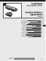
FM-SOLID MANIFOLD
SERIES
INDEX
Module Configuration
Examples of FM-SOLID MANIFOLD X80M Configuration
Module Mass and Dimensions
Manifold Order Codes
Module Order Codes
Wiring Modules
Details of Wiring Specifications
Detailed Diagram of Solenoid Wiring System
Dimensions
Compact Serial Transmission System
Piping Modules
Dimensions
Valve Modules
Cylinder Operating Speed, Flow Rate
Dimensions
Block-off Plate Module
Dimensions
End Blocks
Dimensions
Handling Instructions and Precautions
Important Precautions
Caution
383
385
387
388
391
393
394
396
397
399
403
404
405
406
407
412
413
414
415
417
418
Before use, be sure to read the “Safety Precautions” on p. 31.
382
FM-SOLID MANIFOLD X80M SERIES
VALVES GENERAL CATALOG
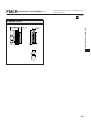
FM-SOLID MANIFOLD
Series
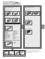
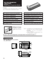
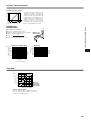
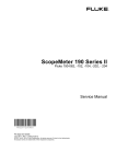
Module Configuration
Wiring modules, p.393
Piping modules, p.403
Flat cable connector type
Built-in quick fitting type
With
マフラ内蔵
built-in
muffler
● Accommodates up to 8 solenoids
(10 pins)
● Accommodates up to 16 solenoids
(20 pins)
D-sub connector type
Terminal block type
Built-in straight quick fitting
With
マフラ内蔵
built-in
muffler
Built-in elbow quick fitting
P port female thread type
With
built-in muffler
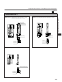
Compact serial transmission system, p.399
All port female thread type
For OMRON
SYSBUS Wire System
For OMRON
CompoBus/S
For OMRON
B7A Link Terminal
For Mitsubishi Electric
MELSECNET/MINI-S3
For Mitsubishi Electric
MELSEC I/O LINK
For Mitsubishi Electric
CC-Link
For Fuji Electric FA
Components & Systems
T Link Mini
For NKE, KURODA
PRECISION INDUSTRIES
UNI-WIRE ® System
For SUNX
S-LINK
For KEYENCE
KZ-R
For KOYO ELECTRONICS
INDUSTRIES
SA Bus
※UNI-WIRE ® System is a serial parallel transmission
system developed jointly by NKE and KURODA
PRECISION INDUSTRIES.
For OMRON
CompoBus/D
●For details of specifications for modules and accessories, etc., see the pages following each title.
●For the FM-SOLID MANIFOLD X80M series order
codes, see p.388.
Cable assembly
p.1039
383
Connector
p.1040
Cable
p.1040
Remote control
box, p.1041
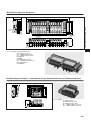
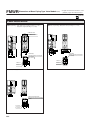
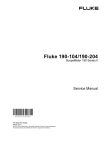
Valve modules (2-, 3-port, 5-port), p.405
Block-off
plate module, p.412
ブロックプレートモジュール256ページ
Single solenoid
FM-SOLID MANIFOLD X80M SERIES
Solenoid valves 090 series
End block
module type
With DIN rail
mounting bracket type
End block
side piping type
End block
upper piping type
Tandem solenoid
Twin solenoid
Base piping type
Single solenoid
End blocks, p.414
●Voltage: DC12V, DC24V
Sticker, p.388
1(P), 3, 5(R) port all port block type
1(P) port block type
3, 5(R) port block type
Port isolator, p.388
DIN rail mounting bracket,
p.388
384
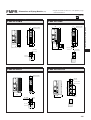
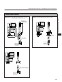
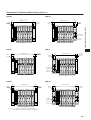
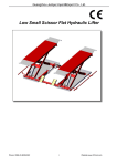
Examples of FM-SOLID MANIFOLD X80M Configuration
Manifold Configuration Example 1.
265.2
57
3 4-φ3.4
3
8×10.2 (Pitch)
4×15 (Pitch)
22
3×20.4 (Pitch)
2×10.2
2×15
(Pitch)
(Pitch)
63
70
PR
3・5(R)
P
4S
01
PR
FM
B
B
A
A
1 2 3 4 5 6 7 8 9 10 11 12 13 14 -PR
01
-FR
PR
FM
FM
FM
WR
WR
09
09
0-4
0-B
S
P-J
2-J
KE
4S
E1
1-J
0E
09
09
WR
WR
FM
FM
0-4
-M
70
50
-T0
-D2
CR
CR
FM
FM
00
00
-F1
-F2
CR
FM
CR
FM
Module No.
-J4
2.6
S
4S
8
(
1 P)
15 16 17 18 19 Note: This is not a manifold configuration for use in actual applications.
Module No.
385
Model
No.1
FMCR-F200
No.2
FMCR-F100
No.3
FMCR-D250-M2.6
No.4
FMCR-T070
No.5
FMWR090E1-J4S
No.6∼12
FMWR090-4E1-J4S
No.13∼15
FMWR090-4KE2-J4S
No.16∼17
FMWR090-BP-J4S
No.18
FMPR-FR01
No.19
FMPR-PR01S
Manifold Configuration Example 2.
226.9
214.2
46.5
22
PR
P
FM-SOLID MANIFOLD X80M SERIES
63
70
R
3, 5(R) Port
P
7
11
P
1(P) Port
2-R1.7
2(B) Port
1(P) Port
46.5
4(A) Port
B
B
A
A
2
Module No.1
3
4
5
6
7
8
↑
9 10
11
12
13
14
15
Order code: X80M-ED No.1 FMCR-D250-M2.6 DC24V
No.2 FMWR090E1-J6S DC24V
No.3∼5 FMWR090-4E1-J6S DC24V
No.6∼7 FMWR090-4KE2-J6S DC24V
No.8 FMPR-FJ8S
No.9 FMBR-P
No.10 FMWR090-4E1-J6S DC24V
No.11∼13 FMWR090-4KE2-J6S DC24V
No.14 FMWR090-BP-J6S
No.15 FMPR-FJ8S
Manifold Configuration Example 3. Combination Mounting of Single Solenoid Valves and Tandem Solenoid Valves
55
A
A
A
A
A
A B
A B
A B
A B
A B
D
B A
B
D
B A
B
D
B A
B
D
B A
A B
B
D
B A
D
B
P
8
7
2-R1.7
Order code: X80M-ED
57
R
PR
A
B
A
63
70
82.6
B
4.6
111.6
96.6
38
B
B
A
Module No.1
A
2
3
4
5
6
7
8
No.1 FMCR-F200 DC24V
No.2 FMWR090-4E1-J4S DC24V
No.3 FMWR090-4E1-J4S-D DC24V
No.4∼6 FMWR090-4ME2-81-J4S DC24V
No.7∼9 FMWR093-4ME2-81-J4S DC24V
9
386
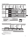
Module Mass and Dimensions
Item
Mass g [oz.]
Width mm [in.]
Height mm [in.]
FMCR-F10□
30 [1.06]
15 [0.59]
57 [2.24]
FMCR-F20□
38 [1.34]
15 [0.59]
57 [2.24]
FMCR-D250-□
44 [1.55]
15 [0.59]
46 [1.81]
FMCR-G250-□
51 [1.80]
15 [0.59]
46 [1.81]
FMCR-T070
37 [1.31]
15 [0.59]
50 [1.97]
80/65 [2.82/2.29]
30.6 [1.205]
66.9 [2.634]
YS111□,YS121□,YS161□,YS171□
105 [3.70]
30.6 [1.205]
66.9 [2.634]
YS181□,YS1A1□,YS1A2□
105 [3.70]
30.6 [1.205]
66.9 [2.634]
YS131□,YS132□,YS1B1□
100 [3.53]
30.6 [1.205]
66.9 [2.634]
YS141□/YS142□
85/70 [3.00/2.47]
30.6 [1.205]
66.9 [2.634]
YS151□/YS152□
66.9 [2.634]
Module type
Wiring module
YS101□/YS102□
Compact serial transmission block
Piping module
Valve module
Block-off plate module
End block
70/67 [2.47/2.36]
30.6 [1.205]
FMPR-FJ8S
36 [1.27]
15 [0.59]
39 [1.54]
FMPR-FJ8L
42 [1.48]
15 [0.59]
55.4 [2.181]
FMPR-FR01
37 [1.31]
15 [0.59]
39 [1.54]
FMPR-PR01S
50 [1.76]
15 [0.59]
40.5 [1.594]
FMWR090E1
42 [1.48]※
10.2 [0.402]
36 [1.42]※
FMWR090-4E1
42[1.48]※
10.2 [0.402]
36 [1.42]※
FMWR090-4KE2
84 [2.96]※
20.4 [0.803]
36 [1.42]※
FMWR090-4ME2
62 [2.19]※
10.2 [0.402]
55.8 [2.197]
FMWR093-4ME2
67 [2.36]※
10.2 [0.402]
55.8 [2.197]
FMWR090-BP
24 [0.85]※
10.2 [0.402]
23.6 [0.929]
X80M
30 [1.06]
6 [0.24]
22.5 [0.886]
X80M-ER
47 [1.66]
Left side 6 [0.24]/Right side 17 [0.67]
22.5 [0.886]
X80M-EL
47 [1.66]
Left side 17 [0.67]/Right side 6 [0.24]
22.5 [0.886]
X80M-ED
64 [2.26]
Left side 17 [0.67]/Right side 17 [0.67]
22.5 [0.886]
X80M-UR
80 [2.82]
Left side 6 [0.24]/Right side 15 [0.59]
39 [1.54]
X80M-UL
80 [2.82]
Left side 15 [0.59]/Right side 6 [0.24]
39 [1.54]
X80M-UD
130 [4.59]
Left side 15 [0.59]/Right side 15 [0.59]
39 [1.54]
X80M-DN
118 [4.16] (88 [3.10])Note
Left side 12.7 [0.500]/Right side 12.7 [0.500]
31 [1.22]
Remark: The heights are those with the end blocks installed.
Note: Figures in parentheses ( ) are the mass for the DIN rail mounting
bracket only.
※: For -J4S
X80M-DN
No.1
FMCR-F100 DC24V
No.2∼9
FMWR090-4E1-J4S DC24V
No.10
FMPR-FJ8S
118+30+336+36=520g [18.34oz.]
30+88=118
30×1 =30
42×8 =336
36×1 =36
FM-SOLID MANIFOLD X80M Series Basic Specifications
Manifold basic model
Item
Media
Air
Operating pressure range MPa {kgf/cm2} [psi.]
Proof pressure
MPa {kgf/cm2} [psi.]
Operating temperature range
(atmosphere and media)
Wiring type
X80M
°C [°F]
0.2 ∼0.7 {2.0 ∼7.1} [29∼102]
1.05 {10.7} [152]
5∼50 [41∼122]
Collective wiring type from wiring module
(Flat cable connector type, D-sub connector type, terminal block type)
End block
End block module type/End block piping type
Manifold mounting type
Direct mounting type/DIN rail mounting type
Common terminal wiring
Positive common/Negative common
387
Manifold Order Codes
Manifold basic model
X80M
End block type
Mounting type
Common terminal wiring
-ED
-DN
-CM
End block
mounting type
End block shape
Blank
-ER
qEnd block
module type
Always specify the
piping module.
(1(P) and 3, 5(R)
ports are plumbed
at the piping
module.)
wEnd block
right side piping type
1(P), 3, 5(R), and PR piping is
possible at the end block. The
piping direction is lateral right
(←direction).
1(P), 3, 5(R) ports: 1/8
PR port: M5
PR port is separated.
eEnd block
left side piping type
Same specification
as the above w.
The piping direction,
however, is lateral
left (→ direction).
-UR
-UL
-UD
rEnd block
both sides piping type
Same specification
as the above w.
The piping direction,
however, can be in
both lateral directions.
tEnd block
upper right side piping type
1(P) and 3, 5(R) piping is
possible at the end block.
The piping direction is
upward right. 1(P) and 3,
5(R) ports: 1/8 (3, 5(R) and
PR share the same 3, 5(R)
port)
yEnd block
upper left side piping type
Same specification
as the above t.
The piping direction,
however, is upward
left.
uEnd block
upper both sides piping type
Same specification as
the above t.
The piping direction,
however, can be in both
upward directions.
Module model
No.1
FMCR-F200 …
No.2
FMWR090-4E1 …
⋮
⋮
No.n
Blank
With DIN rail
mounting bracket type
●Select from the valve modules,
wiring modules, or piping modules.
●One sticker is provided for each
manifold.
Blank
Negative common
-DN
-EL
-ED
Positive common
Module No.
-CM
1. The number of the modules for the FM-SOLID
MANIFOLD X80M series should be 20 stations or
less.
2. When a pressure drop is considered possible, such
as when a multiple number of valves are operated
simultaneously on a multi-station manifold, or
during high cycle applications, add a piping module
at an intermediate position of the manifold.
3. When combining 2 or more terminal block type
wiring modules (FMCR-T070) side by side, the
wiring space for each terminal block becomes tight.
Depending on the wiring types and conditions, each
wiring group’s crimped terminals or lead wires
could interfere with other terminal blocks, and it
could be difficult to achieve an orderly wiring. When
using multiple wiring modules, therefore, carefully
study the designated locations of each module or
consult us.
■ Order codes for additional parts
(To be ordered separately)
●DIN rail mounting bracket (1 set)
●Number stickers (1 set of 5 sheets)
X801-DN
X802-01
■About a port isolator
Use of a port isolator at an intermediate position on the manifold and
installing a piping module to an individual group makes the use of 2 or 3
different pressures possible, and prevents exhaust interference from the main
exhaust. When ordering, enter a port isolator as 1 module.
Port isolator type
Type
Function
FMBR-A
1(P), 3, 5(R) port all port block
FMBR-P
1(P) port block
FMBR-R
3, 5(R) port block
※Although port isolators can be installed into modules at any location, they
cannot be disassembled to change the position after shipping.
388
FM-SOLID MANIFOLD X80M SERIES
Order Codes
Manifold Order Codes (With Compact Serial Transmission Block)
Order Codes
Manifold basic model
Compact serial transmission block
Manufacturer’s
specification
Mounting
location
X80MS1
01 : For UNI-WIRE System (16 outputs)
02 : For UNI-WIRE System (8 outputs)
11 : For Mitsubishi Electric
MELSECNET/MINI-S3
21 : For OMRON
SYSBUS Wire System
31 : For OMRON
B7A Link Terminal (standard)
32 : For OMRON
B7A Link Terminal (high speed)
SA Bus (16 outputs)
41 : For KOYO ELECTRONICS INDUSTRIES
42 : For KOYO ELECTRONICS INDUSTRIES
SA Bus (8 outputs)
51 : For SUNX
S-LINK (16 outputs)
52 : For SUNX
S-LINK (8 outputs)
61 : For Mitsubishi Electric
MELSEC I/O LINK
71 : For Fuji Electric FA Components & Systems
T Link Mini
81 : For KEYENCE KZ-R
A1: For OMRON
CompoBus/S (16 outputs)
A2: For OMRON
CompoBus/S (8 outputs)
B1: For Mitsubishi Electric
CC-Link
Module No.
End block
type
Mounting
type
EL
DN
Module model
No.1 FMWR090-4ME2・・・
⋮
⋮
No.n
●Select from the valve
modules, piping modules, or
Blank: End block mounting type
block-off plate modules.
DN: With DIN rail mounting bracket ●For the voltage
type
specifications of the valve
module, always select
Blank: End block module type
DC24V.
EL: End block left side piping type
ER: End block right side piping type
Note
UL: End block upper left piping type
UR: End block upper right piping type
L: Left side mounting
R: Right side mounting
Note: A piping type end block cannot be designated for
the same side as the compact serial transmission
block mounting location. When selecting an end
block piping type, see the table below:
○: Mounting possible ×: Mounting impossible
End block type
Mounting location
of the compact
serial transmission
block
■Order codes for compact serial transmission block only
EL
ER
UL
UR
L
×
○
×
○
R
○
×
○
×
■Order code for dedicated cable for S-LINK only
YS1
L: Left side mounting
R: Right side mounting
YS151-KB2
(Cable length: 2000mm [79in.])
01 : For UNI-WIRE System (16 outputs)
02 : For UNI-WIRE System (8 outputs)
11 : For Mitsubishi Electric
MELSECNET/MINI-S3
21 : For OMRON
SYSBUS Wire System
31 : For OMRON
B7A Link Terminal (standard)
32 : For OMRON
B7A Link Terminal (high speed)
41 : For KOYO ELECTRONICS INDUSTRIES
SA bus (16 outputs)
42 : For KOYO ELECTRONICS INDUSTRIES
SA bus (8 outputs)
51 : For SUNX
S-LINK (16 outputs)
52 : For SUNX
S-LINK (8 outputs)
61 : For Mitsubishi Electric
MELSEC I/O LINK
71 : For Fuji Electric FA Components & Systems
T Link Mini
81 : For KEYENCE KZ-R
A1: For OMRON
CompoBus/S (16 outputs)
A2: For OMRON
CompoBus/S (8 outputs)
B1: For Mitsubishi Electric
CC-Link
※Order them for maintenance use only.
Internal wiring and mounting screws, etc. are not included.
389
Order Codes for Serial Transmission System for OMRON CompoBus/D
Serial transmission block
Manufacturer’s
specification
X80MS1 -
Mounting
location
End block
type
Mounting
type
Module No.
Module model
91 - L - ER - DN No.1 - FMCR-F201 DC24V
⋮
⋮
No.2 FMWR090-4ME2・・・
⋮
⋮
No.n
●Select from the valve modules,
piping modules, or block-off plate
DN: With DIN rail
modules from No.2 up.
mounting blacket type ●For the voltage specifications in
the configured valve module,
always select DC24V.
Blank: End block module type
ER: End block right side piping type Note2
UR: End block upper right piping type Note2
L: Left side mounting
●For No.1, always enter the wiring
module FMCR-F201 DC24V.Note1
91: For OMRON CompoBus/D
Notes: 1. Since the shape and wiring configuration for the OMRON CompoBus/D differs from those of other serial transmission types, a wiring module is required
as module No.1. For module No.1, always enter wiring module FMCR-F201 DC24V.
2. With the end block type, EL and UL cannot be selected.
■Order code for serial transmission block only
YS391
91: For OMRON CompoBus/D
※Order it for maintenance use only.
Mounting screws, etc. are not included.
390
FM-SOLID MANIFOLD X80M SERIES
Manifold basic model
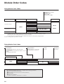
Module Order Codes
Wiring Module Order Codes
Mounting threads for D-sub
connector
M2.6 thread: -M2.6
M3 thread: -M3
#4-40-UNC thread: -UNC
Wiring connecting specification
Wiring module basic type
Wiring basic type
Voltage
-F100
-F101Note 1
Flat cable connector
-F200
FMCR
-D250
D-sub connector
-G250Note 4
Terminal block
DC12V
-F201Note 2
DC24V
-M2.6,-M3,-UNCNote 3
-T070
Notes: 1. -F100 and -F101 differ only in pin locations, and both can be used with up to 8 solenoids. For details, see p.394.
2. -F200 and -F201 differ only in pin locations, and both can be used with up to 16 solenoids. For details, see p.394.
3. When using the cable assembly (FMA-AD250-□), always select -M2.6.
4. For the D-sub connector specifications when a tandem solenoid valve is mounted, always designate -G250.
Remark: For wiring module specifications, see p.393.
Piping Module Order Codes
Port specification
1(P) port built-in quick fitting type (with built-in muffler
on 3, 5(R) port): -FJ
1(P) port female thread type (with built-in muffler on 3, 5(R)
port): -FR
All port female thread type: -PR
Fitting specification
Straight quick fitting for φ8 tube: 8S
Elbow quick fitting for φ8 tube: 8L
Port size
Rc1/8: 01
Piping direction
Upper piping: S
Piping module basic type
-FJ
FMPR
8S, 8L
-FR
-PR
Remark: For piping module specifications, see p.403.
※ The FM-SOLID MANIFOLD X80M series is compatible with the following specifications;
●Pressure switch (electronic type) module
●Wiring module (D-sub connector, side connection specification)
●CS specification
●External pilot specification
For details of specifications, delivery time, etc., consult us.
391
01
S
Valve Module Order Codes
2-, 3-port valve
Valve function
Normally closed (NC): Blank
Normally open (NO): -11
Valve module
basic model
3-position valve
Valve function
Closed center: Blank
Exhaust center: -13
Pressure center: -14
Module base 4(A), 2(B) ports,
port specification
φ4 straight quick fitting
: -J4S
φ4 long straight quick fitting : -J4LS
φ6 straight quick fitting
: -J6S
φ4 elbow quick fitting
: -J4U
M5 female thread type
: -M5M
-2
-11
-81
090-4KE2
090-4ME2
Base piping type module
(tandem solenoid)
093-4ME2
090E1
-13,-14
-2
F1WR
Note 4
-J4S,-J4LSNote 1, -D
-J6S,-J4UNote 3,
-M5M
-CM
-81Note 2
-81
DC12V
DC24V
090-4KE2
090-4ME2
093-4ME2
DC12V
DC24V
-11
090-4E1
Order codes for single
valve unit
Common terminal wiring
Positive common: Blank
Negative common: -CM
Voltage
090-4E1
FMWR
Wiring type
Wiring for single
solenoid: Blank
Wiring for
tandem solenoid
: -D
Basic valve
model
090E1
Base piping type
module
Manual override
Non-locking
type: Blank
Locking type: -81
-13,-14
-81Note 2
Notes: 1. For combination mounting of the straight quick fitting φ4 and φ6 specification modules, select the long straight quick fitting (-J4LS) for the φ4
specification. The protruding dimensions of both fittings become the same.
2. Always enter -81.
3. A 3-position tandem solenoid valve cannot be mounted on the -J4U valve module.
4. Even if the valve mounted at shipping is a single solenoid, 2 control wires (SOL.A., SOL.B) are
Option
connected to the base interior, the same as for a tandem solenoid. If later changed to mount a
tandem solenoid valve, only the valve needs to be changed, and the wiring in the base interior
Manual override
does not need to be changed. But since the wiring module exclusively uses the control pin
Locking type: -81
corresponding to SOL.B, when ordering, pay particular attention to the wiring module’s maximum
number of mountable solenoids, pin number and corresponding SOL. When selecting a tandem
solenoid valve module, there is no need to enter -D. See the pin number and corresponding
solenoid on p.395.
Remark: For valve module specifications, see p. 405.
Block-off Plate Module Order Codes
Module base 4(A), 2(B) ports
connection specification
φ4 straight quick fitting
: -J4S
φ4 long straight quick fitting : -J4LS
φ6 straight quick fitting
: -J6S
φ4 elbow quick fitting
: -J4U
M5 female thread type
: -M5M
Wiring type
Wiring for single
solenoid: Blank
Wiring for tandem
solenoid: -D
Common terminal wiring
Positive common: Blank
Negative common: -CM
Block-off plate module
basic model
Base piping type
FMWR
090-BP
-J4S,-J4LSNote 1
-J6S,-J4UNote 2,-M5M
-DNote 3
-CMNote 4
Notes: 1. For combination mounting of the straight quick fitting φ4 and φ6 specification modules, select the long straight quick fitting (-J4LS) for
the φ4 specification. The protruding dimensions of both fittings become the same.
2. A 3-position tandem solenoid valve cannot be mounted on the block-off plate module with -J4U.
3. Select -D when planning to add on a tandem solenoid valve later. Two control wires (SOL.A and SOL.B) are connected to the base interior.
When ordering, pay attention to the wiring module’s maximum number of mountable solenoids, pin number and corresponding SOL. In
addition, for future use to provide an additional single solenoid valve or twin solenoid valve, leave it blank. See the pin number and
corresponding solenoid on p.395.
4. For mounting tandem solenoid valves, consult us.
Remark: For block-off plate module specifications, see p.412.
■Order code for block-off plate only
■ F1WR090-BP
392
FM-SOLID MANIFOLD X80M SERIES
2-, 3-port valve
Number of ports
3-port: Blank
2-port: -2
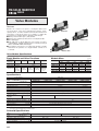
FM-SOLID MANIFOLD
SERIES
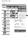
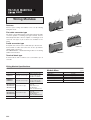
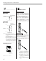
Wiring Modules
FMCR-F200
Features
Achieves space savings and enables lower costs by reducing
wiring man-hours.
FMCR-F100
Flat cable connector type
The range of the module includes a type with a 10-pin flat cable
connector capable of controlling up to eight solenoids, and one
with a 20-pin flat cable connector capable of controlling up to 16
solenoids. Two types of pin locations are available for the
wiring.
D-sub connector type
A 25-pin D-sub connector can accommodate up to 16 solenoids.
Various kinds of cables and connectors are also provided to
simplify wiring connections.
The FMCR-G250 is a dedicated wiring module for mounting
tandem solenoid valves.
FMCR-T070
FMCR-D250
Terminal block type
A terminal block with 7 terminals can accommodate up to 6
solenoids.
Wiring Module Specifications
Module Mass
Wiring module model Wiring connection specification
FMCR-F100
FMCR-F101
FMCR-F200
FMCR-F201
Flat cable connector type
Flat cable connector type
Remarks
FMCR-F10□
30 [1.06]
FMCR-F20□
38 [1.34]
FMCR-D250-□
44 [1.55]
Made by Sumitomo 3M
Box type, with long clip
Part number: 4220-00MILCSC
FMCR-G250-□
51 [1.80]
FMCR-T070
37 [1.31]
Mounting threads for D-sub
connector
-M2.6: M2.6 thread
-M3: M3 thread
-UNC: #4-40-UNC thread
FMCR-G250-M2.6
FMCR-G250-M3 D-sub connector type
FMCR-G250-UNC
Mounting threads for D-sub
connector
-M2.6: M2.6 thread
-M3: M3 thread
-UNC: #4-40-UNC thread
FMCR-T070
Terminal block thread: M3
393
g [oz.]
Mass
Made by Sumitomo 3M
Box type, with long clip
Part number: 4210-00MILCSC
FMCR-D250-M2.6
FMCR-D250-M3 D-sub connector type
FMCR-D250-UNC
Terminal block type
Type
Details of Wiring Specifications
Number of Solenoids Which Can Be Connected to a
Wiring Module (Possible Number of Connections)
Number of pins (terminals)
8
10 pins
16
20 pins
16
25 pins
FMCR-F101
FMCR-F200
FMCR-F201
wertyui
Flat cable
connector
(-F200)
D-sub connector (-D250)q w e r t y u i o !0 !1 !2 !3 !4 !5 !6
(-G250)
Flat cable connector (-F201) q w e r t y u i !1 !2 !3 !4 !5 !6 !7 !8
(-T070) q
Terminal
werty
FMCR-D250-M2.6
FMCR-D250-M3
1 2 3 4
Solenoid No.
FMCR-D250-UNC
5 6 7 8 9 10 11 12 13 14 15 16
FMCR-G250-M2.6
FMCR-G250-M3
16
25 pins
6
7 terminals
FMCR-G250-UNC
FMCR-T070
1 2 3 4 5 6 Module No.
Wiring module
7
8 9 10 11
12
Valve module
13
14
Piping module
Wiring Module Pin (Terminal) Locations
●FMCR-F100
●FMCR-F201
Flat cable connector
Triangle mark
Flat cable connector
Triangle mark
9
7
5
3
1
11
12
13
14
15
16
17
18
19
20
10
8
6
4
2
1
2
3
4
5
6
7
8
9
10
1∼8: Control pins
9, 10: Common pins(short-circuited within the module)
●FMCR-F101
Flat cable connector
●FMCR-D250,G250
D-sub connector
Triangle mark
9
7
5
3
1
10
8
6
4
2
111∼8: Control pins
11∼18: Control pins
9, 19: (−) pins(short-circuited within the module)
10, 20: (+) pins(short-circuited within the module)
3
1
2
1∼8: Control pins
9: (−) pin
10: (+) pin
5
7 9 11 13 15
4 6 8 10 12 14 16
17
19
18
23
21
20
22
25
24
1∼16: Control pins
20, 21, 22: (−) pins(short-circuited within the module)
23, 24, 25: (+) pins(short-circuited within the module)
●FMCR-F200
Triangle mark
Flat cable connector
19
17
15
13
11
9
7
5
3
1
20
18
16
14
12
10
8
6
4
2
1∼16: Control pins
17, 18: (−) pins(short-circuited within the module)
19, 20: (+) pins(short-circuited within the module)
Notes: 1. The above pin numbers are assigned based on the solenoid valve wiring
sequence for the sake of convenience.
2. The D-sub connector differs from the pin locations and numbers (marked)
defined in JIS X5101 for the data circuit-terminating equipment (DCE). Caution
should be exercised.
●FMCR-T070
Terminal Solenoid side
block
1
A, B port side
2
3
4
5
6
7
1∼6: Control terminals
7: Common terminal
The flat cable connector and D-sub connector pin locations can be adapted to specifications other than those listed above.
394
FM-SOLID MANIFOLD X80M SERIES
Number of solenoids
FMCR-F100
Pin number
(-F100)
q
(-F101)
(1 solenoid for 4E1 type, and 2 solenoids for 4KE2 type)
Wiring module model
Solenoid Layout
Details of Wiring Specifications
●Pin number and corresponding solenoid (for combination mounting of single solenoid valves and tandem solenoid valves)
X80M-ED
No.1-FMCR-F200 DC24V
No.2-FMWR090-4E1-J4S DC24V
No.3-FMWR090-4E1-J4S-D DC24V
No.4∼6-FMWR090-4ME2-81-J4S DC24V
No.7∼9-FMWR093-4ME2-81-J4S DC24V
Pin locations
Pin No. : 1
SOL.A } First solenoid valve: Single solenoid (wiring as single solenoid)
2
SOL.A
Second solenoid valve: Single solenoid (wiring as tandem solenoid: -D)Note 2
3 (SOL.B)Note 1
4
SOL.A
Third solenoid valve: Tandem solenoid
5
SOL.B
6
SOL.A
4th solenoid valve: Tandem solenoid
7
SOL.B
⋮
⋮
20 19
}
}
}
18 17
16 15
14 13
12 11
Module No. 1 2 3 4 5 6 7 8 9
10
9
8
7
6
5
4
3
2
1
14
15
16
17,18
19,20
SOL.A
SOL.B
Not used
(−) pins
(+) pins
} 8th solenoid valve: Tandem solenoid
Note 1: (SOL.B) shows that the wiring module control pin is assigned and the wire is connected
to the valve base interior.
Note 2: Even if the valve mounted at shipping is a single solenoid, 2 control wires (SOL.A., SOL.B)
are connected to the base interior, the same as for a tandem solenoid. If later changed to
mount a tandem solenoid valve, only the valve needs to be changed, and the wiring in the
base interior does not need to be changed. But since the wiring module exclusively uses the
control pin corresponding to SOL.B, when ordering, pay particular attention to the wiring
module’s maximum number of mountable solenoids, pin number and corresponding SOL.
When selecting a tandem solenoid valve module, there is no need to enter -D.
●Pin number and corresponding solenoid(FMCR-G250-□)
X80M
No.1 -FMCR-G250-M2.6 DC24V
No.2,3-FMWR090-4ME2-81-J6S DC24V
No.4∼7-FMWR090-4E1-J6S-D DC24V
No.8-FMWR090-BP-J6S-D DC24V
No.9-FMPR-FJ8S
Module No.1 2 3 4 5 6 7 8 9
Pin locations
2
4
6
8
10
12
14
16
18
20
22
24
1
3
5
7
9
11
13
15
17
19
21
Pin No. : 1
2
3
4
5
6
7
8
⋮
13
14
⋮
20,21,22
23,24,25
SOL.A
B
A
B
SOL.A
(SOL.B)Note
SOL.A
(SOL.B)Note
⋮
(SOL.A)Note
(SOL.B)Note
⋮
(−) pins
(+) pins
} First solenoid valve: Tandem solenoid
} Second solenoid valve: Tandem solenoid
} Third solenoid valve: Single solenoid
} 4th solenoid valve: Single solenoid
} Block-off plate
23
25
Note: (SOL.A) (SOL.B) show that the control pins in the wiring module are assigned and
the wires to SOL.A and SOL.B are connected to the valve base interior.
395
Detailed Diagram of Solenoid Wiring System
Flat cable connector and D-sub connector
Terminal block
● Positive common
● Positive common
-F200:1∼16
-F201:1∼8, 11∼18
n -D250,-G250:1∼16
-F100:None
-F101:9
-F200:17,18
-F201:9,19
-D250,-G250:20,21,22
● Negative common
Built-in into the base
-F100:9,10
-F101:9
-F200:17,18
-F201:9,19
-D250,-G250:20,21,22
1
6
● Negative common
7 negative terminal (common)
-F200:1∼16
-F201:1∼8, 11∼18
n
-D250,-G250:1∼16
-F100:None
-F101:10
-F200:19,20
-F201:10,20
-D250,-G250:23,24,25
Built-in into the base
1 -F100:1∼8
-F101:1∼8
FM-SOLID MANIFOLD X80M SERIES
-F101:1∼8
Solenoid
7 positive terminal (common)
Built-in into the base
1 -F100:1∼8
LED for
Power supply
Solenoid
Built-in into the base
-F100:9,10
-F101:10
-F200:19,20
-F201:10,20
-D250,-G250:23,24,25
1
6
The flat cable connector and D-sub connector pin locations can be adapted to specifications other than those listed above.
396
FMCR Dimensions of Wiring Module
(mm)
※Height with end block attached is +1mm [0.039in.] longer
than indicated below.
X80M-FMC
Flat cable connector type
Flat cable connector type
FMCR-F100/-F101
FMCR-F200/-F201
56
15
1.7
38
Flat cable connector
made by Sumitomo 3M Ltd.
4210-00M1LCSC
15
1.7
56
38
Flat cable connector
made by Sumitomo 3M Ltd.
4220-00M1LCSC
Power supply terminal
9.5
9.5
40
40
70
70
Power supply terminal
LED Indicator
LED Indicator
Note: For the -F100, the power supply terminal is not wired.
D-sub connector type
D-sub connector type
FMCR-D250-M2.6/-M3/-UNC
FMCR-G250-M2.6/-M3/-UNC
45
38
Select from the following:
-M2.6(M2.6 thread)
-M3(M3 thread)
-UNC(#4-40-UNC thread)
45
38
15
Select from the following:
-M2.6(M2.6 thread)
-M3(M3 thread)
-UNC(#4-40-UNC thread)
15
D-sub connector
D-sub connector
Power supply
terminal
43
9.5
9.5
43
70
70
Power supply
terminal
LED Indicator
20.4
LED indicator
397
FMCR Dimensions of Wiring Module
(mm)
※Height with end block attached is +1mm [0.039in.] longer
than indicated below.
X80M-FMC
Terminal block type
15
Terminal
block
(55)
M3 screw
70
49
38
FM-SOLID MANIFOLD X80M SERIES
FMCR-T070
398
FM-SOLID MANIFOLD
SERIES
Compact Serial Transmission System
Features
A manifold with compact serial transmission block, corresponding to each manufacturer’s serial transmission system.
For OMRON SYSBUS Wire System
For Mitsubishi Electric MELSECNET/MINI-S3
For OMRON CompoBus/S
For Mitsubishi Electric MELSEC I/O LINK
For OMRON CompoBus/D Note
For Mitsubishi Electric CC-Link
For OMRON B7A Link Terminal
For Fuji Electric FA Components & Systems T Link Mini
For NKE,
KURODA PRECISION INDUSTRIES UNI-WIRE® System
For KEYENCE KZ-R
For SUNX S-LINK
For KOYO ELECTRONICS INDUSTRIES SA Bus
Note: OMRON’s remote I/O adapter-type
DRT1-OD16X is used in the serial
transmission block for OMRON’s
CompoBus/D. For details, see
OMRON’s catalog, user’s manual,
etc.
Remarks: 1. The UNI-WIRE® system is a serial parallel transmission system
developed jointly by NKE and KURODA PRECISION
INDUSTRIES.
2. For the details of each system, see each manufacturer’s
catalog, user’s manual, etc.
3. For details on handling the corresponding manifolds, see the
corresponding Koganei user’s manuals.
Example of Manifold Configuration for Compact Serial Transmission System
Configuration Example1
X80MS1-A1-L
No.1∼8 - FMWR090-4ME2-81-J4S DC24V
No.9 - FMPR-PR01S
102.6
MADE IN JAPAN
0
B
A
A
A B
B
0
B
A
A
A B
B
0
B
A
A
A B
B
0
B
A
A
A B
B
0
B
A
A
A B
B
0
B
A
A B
3, 5(R)Port
B
0
B
A
0
1 2 4 8 NC HOLD
B
PR
PWR COMM ERR
P
1(P)Port
8
R
(3.5)
BS+ BDH BDL BS- FG
YS1A1L
A
A
A B
B
70
A
A B
B
63
A
(3)
4.6
139.2
4-φ3.4
2(B)Port
30.6
399
B
B
A
A
6
8×10.2(Pitch)
15 6
22.5
66.9
4(A)Port
(mm)
Example of Manifold Configuration for Compact Serial Transmission System
(mm)
Configuration Example 2
X80MS1-A1-L
No.1∼16 - FMWR090-4E1-J6S DC24V
No.17-- FMPR-PR01S
220.8
(3)
184.2
MADE IN JAPAN
70
11
FM-SOLID MANIFOLD X80M SERIES
63
(3.5)
1 2 4 8 NC HOLD
BS+ BDH BDL BS- FG
YS1A1L
3, 5(R)Port
PR
R
PWR COMM ERR
P
1(P)Port
4-φ3.4
2(B)Port
30.6
Configuration Example 3
B
B
A
A
16×10.2(Pitch)
6
22.5
66.9
4(A)Port
15 6
For CompoBus/D
X80MS1-91-L-DN
No.1-- FMCR-F201 DC24V
No.2∼17 - FMWR090-4E1-J6S DC24V
No.18-- FMPR-PR01S
348
85
211.9
199.2
3, 5(R)Port
(5)
8
DRT1-OD16X
PR
OUT
81
NS
76
MS
63
50
35
5.5
REMOTE ADAPTER 24VDC
R
(5)
P
1(P)Port
2(B)Port
A
(71.5)
B
A
(53.5)
B
39
4(A)Port
12
40
(44.5)
Serial transmission block
OMRON remote adapter
Model: DRT1-OD16X
400
Compact Serial Transmission System Specifications
General Specifications
Voltage
DC24V ±10%
Operating temperature range
5∼50°C [41∼122°F]
Vibration resistance
49.0m/s2 {5.0G} (Conforms to JIS C 0911)
Shock resistance
98.1m/s2 {10.0G} (Conforms to JIS C0912)
● For details of specifications, see the user’s manuals (see below).
Compact Serial Transmission Block, Terminal Block (LED) Names
●For UNI-WIRE® System
●For Mitsubishi Electric MELSECNET/MINI-S3
●For OMRON SYSBUS Wire System
Transmission block specification: -01 (16 outputs), -02 (8 outputs)
Transmission block specification: -11
Transmission block specification: -21
0 1 E
5 6
G
24V
3
0V
4
5
6
7
D
8
G
SD
24V
0V
LED indicator
RDA
RD
0 1 E
7 8
4
D
2
9
2 3
2 3
1
3
OFF
RDB
1
2
3
4
5
6
9
7 8
3
ON
5 6
PWR RUN ERR
POWER SEND
OFF
SDA
SDB
TERM
SG
FG
24V
Description
Indicator
PWR
•Lights up when power is turned on
POWER
•Lights up when power is turned on
•Flashes during voltage drops or
when over current (a short circuit)
RUN
•Lights up for normal data communication with master station
•Flashes during normal transmission
•Lights up or shuts off during faulty transmission
SD
•Flashes during sending data
RD
•Flashes during receiving data
ERR
•Lights up when data receiving error occurs,
shuts off for normal communication
※The UNI-WIRE® System is a serial parallel transmission
system developed jointly by NKE and KURODA
PRECISION INDUSTRIES. For details of the UNIWIRE System, see the NKE or KURODA PRECISION
INDUSTRIES catalog, user’s manual, etc.
● Number
of outputs per block
16 solenoids (transmission block specification: -01)
8 solenoids (transmission block specification: -02)
● Related
materials: User’s manual, document No.
HV005
+
0V
E. C. MODE switch
LED indicator
Remarks
ON
ON
Indicator
SEND
Dip switch for various settings
T/R
RUN ERR
ADDRESS
×10
×1
O
N
Rotary switch for station number setting
4
Address setting switch
Description
−
FG
24V
0V
End station setting switch
LED indicator
Indicator
Description
• Lights up when transmission is normal, and the PC
RUN
is in operations mode or monitor mode
•Flashes during normal transmission
•Lights up during standby or faulty transmission
•Shuts off during faults (during watchdog timer fault)
T/R
ERR
Remarks
● Master
Remarks
● Master
station: MELSEC-A series
AJ71PT32-S3, AJ71T32-S3, A2CCPU/A2CJCPU,
A1SJ71PT32-S3, link sub-stations up to a maximum of 64
stations, and link I/O numbers up to a maximum of 512.
※For details, see the Mitsubishi Electric’s sequencer
MELSEC-A series catalog, user’s manual, etc.
● Number of outputs per block
Maximum of 16 solenoids
※Since the block is equivalent to 2 stations, if substations are entirely composed of the blocks, the
maximum becomes 32 units.
station unit: SYSMAC-C (CV) series
C200H-RM201, C500-RM201
※For details, see the OMRON’s programmable controller
SYSMAC C(CV) series catalog, user’s manual, etc.
● Number
of outputs per block
Maximum of 16 solenoids
● Related materials: User’s manual, document No.
HV007
● Related materials: User’s manual, document No.
HV006
●For OMRON B7A Link Terminal
●For KOYO ELECTRONICS INDUSTRIES SA Bus
●For SUNX S-LINK
Transmission block specification: -31 (standard type), -32 (high speed type)
Transmission block specification: -41 (16 outputs), -42 (8 outputs)
Transmission block specification: -51 (16 outputs), -52 (8 outputs)
1 2 3 4 5 6 7 8
POWER ERROR
ON
PWR ERR
LOAD
OFF
Switch for address setting and output
processing setting during error occurrence
Station number setting switch
Output selecting switch in faulty operation
POWER SEND
ON
HOLD
1
24V
ERR
SIG
0V
LED indicator
L+
L-
SHLD
L24V
LED indicator
G
D
0V
2
3
24V
4
5
6
G
7
8
D
0V
24V
LED indicator
Indicator
Description
Indicator
Description
Indicator
Description
PWR
•Lights up when power is turned on
Power
•Lights up when power is turned on
POWER
•Lights up when power is turned on
ERR
•Lights up during faulty transmission
Error
•Lights up during faulty transmission or other faults
SEND
•Flashes during normal transmission
•Lights up or shuts off during faulty transmission
Remarks
Remarks
● Connection
method: 1 to 1
(Transmission block spec.) Standard type (-31) High speed type (-32)
Transmission delay time
Max.31ms
Max.5ms
Transmission distance
Max.500m
Max.100m
※For details of the B7A Link Terminal, see the
OMRON catalog, user’s manual, etc.
※For details of the SA Bus system, see the KOYO
ELECTRONICS INDUSTRIES catalog, user’s
manual, etc.
Remarks
● Number
● Number
● Number
● Related
● Related
of outputs per block
Maximum of 16 solenoids
● Error
output specifications
Output mode: NPN open collector
Rated load voltage: DC24V
Output current: Sink current MAX. 40mA
● Related
HV008
401
materials: User’s manual, document No.
of outputs per block
16 solenoids (transmission block specification: -41)
8 solenoids (transmission block specification: -42)
HV009
materials: User’s manual, document No.
※ For details of the S-LINK System, see the SUNX
catalog, user’s manual, etc.
of outputs per block
16 solenoids (transmission block specification: -51)
8 solenoids (transmission block specification: -52)
HV010
materials: User’s manual, document No.
●For Mitsubishi Electric MELSEC I/O LINK
Transmission block specification: -61
●For Fuji Electric FA Components
& Systems T Link Mini
●For KEYENCE KZ-R
Transmission block specification: -81
Transmission block specification: -71
0V
3
S2
9
SD
FG
24V
0V
S+
S−
RUN
7 8 9A
ON/OFF switch for terminating resistance
LED indicator
LED indicator
Description
Indicator
PW
•Lights up when power is turned on
•Lights up when receiving data transmitted
from master unit is normal
PWR
•Lights up when power is turned on
ALM
•Lights up during faulty transmission
SD
•Lights up during sending data to master unit
RD
•Lights up during receiving data from master unit
ERR.
•Lights up when faulty data transmitted from master unit
remote I/O unit connection stations, for a maximum
of 128 inputs/outputs
※For details, see Mitsubishi Electric’s sequencer catalog,
user’s manual, etc.
Description
Remarks
※For details of the T Link Mini, see the Fuji Electric
FA Components & Systems catalog, user’s
manual, etc.
0V
Description
•Green: Lights up for normal
communications state
•Orange: Lights up when communications state is poor
(can also light up when
address settings are
incorrect)
•Red:
Lights up during faulty
operation, or when
transmission is cut off
POWER/
ERROR
materials: User’s manual, document No.
Remarks
HV012
※For details of the KZ-R, see the KEYENCE
catalog, user’s manual, etc.
● Number
of outputs per block
Maximum of 16 solenoids
※Since the block is equivalent to 4 stations, if substations are entirely composed of the blocks, a
maximum of 4 units can be connected to 1 master unit.
● Related
Indicator
of outputs per block
Maximum of 16 solenoids
● Related
24V
Error holdiing switch
● Number
Remarks
● 16
FG
LED indicator
Indicator
RUN
0 1 E
ERROR MODE
HOLD
CLEAR
OFF
S1
ADDRESS
● Number
of outputs per block
Maximum of 16 solenoids
● Related
materials: User’s manual, document No.
HV013
materials: User’s manual, document No.
HV011
● For OMRON CompoBus/D
●For OMRON CompoBus/S
●For Mitsubishi Electric CC-Link
Transmission block specification: -91
Transmission block specification: -A1 (16 outputs), -A2 (8 outputs)
Transmission block specification: -B1
B RATE
×10
BS−
24G
FG
0
8
8
8
1
2
3
4
5
6
BDL
6
BS+ BDH
ON
4
10
6
1
0
2
SD
CLEAR
2
HOLD
NS
4
O
N
0
2
Dip switch
MS
STATION NO.
×1
PW L RUN L ERR.
6
PWR COMM ERR
Station number setting switch
Transmission speed setting switch
4
Dip switch for various settings
RD
+24V (FG)
SLD
DG
DB
DA
HOLD/CLEAR switch
Transmission connector Power supply terminal for internal circuit
LED indicator
Indicator
State
Lights up
MS
LED indicator
Color
Green
Flashing
•No setting state
Lights up
•Serious breakdown
Red
Flashing
•Minor breakdown
Shuts off
Lights up
•No power supply
Green
Flashing
NS
Description
•Normal state
Lights up
•Communication connection completed
•No communication connection
•Serious communication fault
Indicator
State
Lights up
PWR
Shuts off
COMM
Lights up
Shuts off
Lights up
ERR
Shuts off
LED indicator
Color
Green
Yellow
Red
Description
PW
•Power not supplied
L RUN
SD
•Lights up during sending data
•Communication fault occurred
RD
•Lights up during receiving data
•During normal communication, or standby
Remarks
※For details of the CompoBus/S, see the OMRON
catalog, user’s manual, etc.
Shuts off
•No power supply
● Number
※For details of the CompoBus/D, see the OMRON
catalog, user’s manual, etc.
※ The transmission block is OMRON’s remote
adaptor-type DRT1-OD16X. For details about
handling, see OMRON’s user’s manual.
● Number of outputs per block
Maximum of 16 solenoids
● Related materials: User’s manual, document No.
HV014
of outputs per block
16 solenoids (transmission block specification: -A1)
8 solenoids (transmission block specification: -A2)
● Related
HV015
•Lights up when normal data is received
from master station
•Communication fault, or standby
•Minor communication fault
Remarks
Description
•Lights up when power is turned on
•During normal communication
Flashing
Red
Indicator
•During power supply
materials: User’s manual, document No.
L ERR.
•Lights up during transmission errors, and
shuts off when time is over
Lights up during station number setting error
or transmission speed setting error
Remarks
※For details of the CC-Link, see the Mitsubishi Electric
catalog, user’s manual, etc.
● Number
of outputs per block
16 solenoids (transmission block specification: -B1)
※Since the block occupies 1 station, if remote I/O
stations are entirely composed of the blocks, a
maximum of 64 units can be connected to 1 master
station.
● Related
materials: User’s manual, document No.
HV016
■ For about specifications and handling details, see the above-listed user’s manuals (document Nos. HV005∼HV016).
402
FM-SOLID MANIFOLD X80M SERIES
24V
POWER/ERROR
0 1 E
7 8
7 8
5 6
FG
4
DG
9
2 3
ON
RD
3
7 8
0 1 E
2 3
BCDE
9
2 3
DATA
3
3456
SD
PWR ALM
E
2
F01
5 6
3
4
ST. NO.
RUN ERR.
Address setting switch
5 6
PW
Station number setting switch
ADDRESS
×10
×1
4
Station number setting switch
FM-SOLID MANIFOLD
SERIES
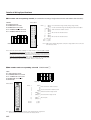
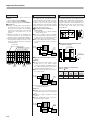
Piping Modules
Features
FMPR-FJ8L
Selectable according to piping requirements, for reducing of piping
work, and easier maintenance.
Built-in quick fitting type
FMPR-FJ8S
The 1(P) port offers 2 types (straight and elbow types) of built-in
quick fittings for theφ8 tube. The 3, 5(R) port is equipped with a
built-in muffler.
1(P) port female thread type
The 1(P) port has an Rc1/8 female thread.
The 3, 5(R) port has a built-in muffler.
All port female thread type
The 1(P) port has an Rc1/8 female thread.
The 3, 5(R) port and PR port have captured exhausts.
FMPR-PR01S
FMPR-FR01
Piping Module Specifications
Module Mass
Model
1(P) port specification
FMPR-FJ8S
With straight quick fitting for φ8 tube
FMPR-FJ8L
With elbow quick fitting for φ8 tube
FMPR-FR01
Rc1/8 (female thread specification)
FMPR-PR01S
403
Rc1/8 (female thread specification)
3, 5(R) port specification
With built-in muffler
(exhausts to atmosphere)
Rc1/8 (female thread specification,
3, 5(R) and PR (captured exhausts))
Model
g [oz.]
Mass
FMPR-FJ8S
36 [1.27]
FMPR-FJ8L
42 [1.48]
FMPR-FR01
37 [1.31]
FMPR-PR01S
50 [1.76]
FMPR
Dimensions of Piping Module
(mm)
※Height with end block attached is +1mm [0.039in.] longer
than indicated below.
X80M-FMP
Built-in elbow quick fitting type
FMPR-FJ8S
FMPR-FJ8L
38
Exhaust outlet
15
70
65
65
Exhaust outlet
15
FM-SOLID MANIFOLD X80M SERIES
Built-in straight quick fitting type
P
15
16.5
P
38
31.5
23
1(P)Port
Quick fitting
Quick fitting
30
1(P)Port
1(P) port female thread type
All port female thread type
FMPR-FR01
FMPR-PR01S
15
Exhaust outlet
15
3-Rc1/8
3, 5(R)Port
70
18
PR
P
P
38
38
1(P)Port
1(P)Port
Rc1/8
30
14(Width
across flats)
11
8
30
R
404
FM-SOLID MANIFOLD
SERIES
Valve Modules
Features
Mounts the compact, low power consumption 090 series
solenoid valves, and offers modularized compact, largecapacity valves, as well as tandem solenoid valves that have 2
solenoids in 1 unit in the space for 1 module, to enable the
achievement of a highly efficient, optimum system design.
●Offers powerful control up to φ40 cylinders.
●Effective area 3.5mm2〔Cv
/
0.2〕
/Power consumption 0.5W.
●Base piping type
●4(A), 2(B) ports on the module base offer a range of 4 types
of quick fittings, straight and elbow types for both φ4 and φ6
tubes, and an M5 female thread type.
●The tandem solenoid uses a locking type manual override
that allows the operation of a single manual override for 2
solenoids.
FMWR090E1
FMWR090-4E1
FMWR090-4KE2
Valve Module Specifications
Basic Models and Valve Functions
Module Mass
g [oz.]
Solenoid valves 090
series
FMWR090E1 FMWR090-4E1 FMWR090-4KE2 FMWR090-4ME2 FMWR093-4ME2
base piping type
Number of positions
2 positions
3 positions
-J4S
-J4LS
-J6S
-J4U
-M5M
FMWR090E1
42 [1.48]
45.5 [1.60]
48 [1.69]
42 [1.48]
42 [1.48]
Number of ports
2, 3 ports
FMWR090-4E1
42 [1.48]
45.5 [1.60]
48 [1.69]
42 [1.48]
42 [1.48]
FMWR090-4KE2
84 [2.96]
91 [3.21]
96 [3.39]
84 [2.96]
84 [2.96]
Valve function
Normally closed
(NC) or
Normally open
(NO), optional
FMWR090-4ME2
62 [2.19]
65.5 [2.31]
68 [2.40]
62 [2.19]
62 [2.19]
FMWR093-4ME2
67 [2.36]
70.5 [2.49]
73 [2.57]
―
67 [2.36]
5 ports
Single
solenoid
Twin
solenoid
Tandem
solenoid
Closed center
(standard), exhaust
center (optional) or
pressure center
(optional)
Mass
Model
Remark: For optional specifications and order codes, see p.392.
Specifications
Solenoid valve
090 series
Basic model
Item
Base piping type
FMWR090E1
FMWR090-4E1
Media
FMWR090-4ME2
FMWR093-4ME2
Air
Operation type
Internal pilot
Effective area〔Cv〕
3.5〔0.2〕
mm2
Port size
3.0〔0.17〕
Dedicated to manifold use.
Lubrication
Operating pressure range
Proof pressure
Response
FMWR090-4KE2
timeNote
ON/OFF
Not required
MPa {kgf/cm2} [psi.]
0.2∼0.7 {2.0∼7.1} [29∼102]
MPa {kgf/cm2} [psi.]
ms DC12V, DC24V
Maximum operating frequency
Hz
Minimum time to energize for self holding
ms
1.05 {10.7} [152]
14/20 or below
5
―
Operating temperature range (atmosphere and media) °C [°F]
Shock resistance
14
50
5∼50 [41∼122]
m/s2 {G}
1373.0 {140.0} (Axial direction 245.2 {25.0})
Mounting direction
Any
Note: Values when air pressure is 0.5MPa {5.1 kgf/cm2} [73psi.]. The value for 090-4KE2, 090-4ME2 is when switching from the opposite position, and for 093-4ME2 is for the closed
center valve, when switching from the neutral position.
Solenoid Specifications
Rated voltage
Item
Type
Operating voltage range (±10%)
V
Current (when rated voltage is applied) mA
Power consumption
W
Note: Diode for surge suppression is built into the base.
405
DC12V
DC24V
With LED indicator (with diode for surge suppressionNote)
10.8∼13.2
21.6∼26.4
40
20
0.5 (with LED indicator)
Cylinder Operating Speed
Cylinder stroke
Cylinder operating speed
t1
t2
Solenoid Cylinder
valve start
energized
t3
Time
Cushioning Cylinder
impact stop
To obtain the time required for the
cylinder to complete 1 stroke, add
cylinder’s delay time t 1 (time between
energizing of the solenoid valve and
actual starting of the cylinder), to the
cylinder’s max. speed operating time t2.
When a cushion is used, add the
cushioning time t 3 , to the above
calculation. The standard cushioning
time t3 is approximately 0.2 seconds.
FM-SOLID MANIFOLD X80M SERIES
FMWR090-4E1
FMWR090-4ME2
Load
Measurement conditions
●Air pressure: 0.5MPa{5.1kgf/cm2} [73psi.]
●Piping inner diameter and length: φ4×1000mm [39in.]
●Fitting:φ6 straight quick fitting (-J6S)
Load
(%)
●Load ratio=
Cylinder theoretical thrust
●Cylinder stroke: 150mm [5.91in.] for φ20∼φ40
FMWR090-4E1
FMWR090-4ME2
0.5MPa
Maximum operating speed
1000
800
φ20
φ25
φ32
φ40
600
400
200
0
Delay time
s 1.0
0.9
0.8
0.7
0.6
0.5
0.4
0.3
0.2
0.1
0
Delay time
Maximum operating speed
mm/s 1200
φ40
φ32
φ25
φ20
10 20 30 40 50 60 70
%
Load ratio
10 20 30 40 50 60 70
%
Load ratio
1mm/s = 0.0394in./sec.
Flow Rate
Valve outlet pressure
MPa
Supply pressure
(MPa)
0.7
0.7
0.6
0.6
0.5
0.5
0.4
0.4
0.3
0.3
0.2
0.1
0
0.2
FMWR090E1
FMWR090-4E1
FMWR090-4KE2
FMWR090-4ME2
60 120 180 240 300
Flow rate R/min (ANR)
0.1
How to read the graph
When the supply pressure is 0.5MPa [73psi.] and flow
rate is 170R/min [6.0ft.3/min.] (ANR), the valve outlet
pressure becomes 0.4MPa [58psi.].
406
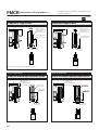
FMWRDimensions of Base Piping Type Valve Module
(mm)
※Height with end block attached is +1mm
[0.039in.] longer than indicated below.
X80M-FW1
2-, 3-port
FMWR090E1
●With quick fittings: -J4S,-J4LS (built-in straight quick fittings for φ4 tube)
-J6S (built-in straight quick fittings for φ6 tube)
●With elbow quick fittings: -J4U (built-in elbow quick fittings for φ4 tube)
LED indicator
10.2
14
35
2(B)Port
2-Quick fittings
5.3 10.4
21
8(-J4S)
11(-J4LS,-J6S)
18
4.4
22
9
62.7
70
Manual override
2-Quick fittings
15.4
2(B)Port
4(A)Port
4(A)Port
Note: For FMWR090E1, the 2(B) port is plugged, while for FMWR090E1-11, the
4(A) port is plugged (φ4: UP-4, φ6: UP-6).
3
●M5 female thread type: -M5M
2(B)Port
5.3 10.4
2-M5×0.8 female thread type
4(A)Port
Note: For FMWR090E1, the 2(B) port is plugged, while for FMWR090E1-11, the
4(A) port is plugged (M5: PF).
407
Note: For FMWR090E1, the 2(B) port is plugged, while for FMWR090E1-11, the
4(A) port is plugged (φ4: UP-4).
※Height with end block attached is +1mm [0.039in.] longer than indicated below.
X80M-FW1
Single solenoid valve
FMWR090-4E1
10.2
●With elbow quick fittings: -J4U (built-in elbow quick fittings for φ4 tube)
FM-SOLID MANIFOLD X80M SERIES
●With quick fittings: -J4S,-J4LS (built-in straight quick fittings for φ4 tube)
-J6S (built-in straight quick fittings for φ6 tube)
LED indicator
14
35
2(B)Port
2-Quick fittings
5.3 10.4
21
8(-J4S)
11(-J4LS,-J6S)
18
4.4
22
9
62.7
70
Manual override
2-Quick fittings
15.4
2(B)Port
4(A)Port
4(A)Port
3
●M5 female thread type: -M5M
2(B)Port
5.3 10.4
2-M5×0.8 female thread type
4(A)Port
408
FMWRDimensions of Base Piping Type Valve Module
※Height with end block attached is +1mm
[0.039in.] longer than indicated below.
(mm)
X80M-FW2
Twin solenoid valve
FMWR090-4KE2
●With quick fittings: -J4S, -J4LS (built-in straight quick fittings for φ4 tube)
-J6S (built-in straight quick fittings for φ6 tube)
20.4
●With elbow quick fittings: -J4U (built-in elbow quick fittings for φ4 tube)
2-LED indicators
35
4-Quick fittings
Right side 4(A), 2(B) ports are plugged.
2(B)Port
4(A)Port
10.2
3
3
●M5 female thread type: -M5M
4-M5×0.8 female thread type
Right side 4(A), 2(B) ports are plugged.
5.3 10.4
(M5: PF)
2(B)Port
4(A)Port
409
4-Quick fittings
Right side 4(A), 2(B) ports are plugged.
15.4
(φ4: UP-4)
φ4:UP-4
φ6:UP-6
5.3 10.4
14
10.2
18
4.4
8(-J4S)
11(-J4LS,-J6S)
21
22
9
70
62.7
2-Manual overrides
2(B)Port
4(A)Port
※Height with end block attached is +1mm [0.039in.] longer than indicated below.
Tandem solenoid valve
FMWR090-4ME2
●With elbow quick fittings: -J4U (built-in elbow fittings for φ4 tube)
FM-SOLID MANIFOLD X80M SERIES
●With quick fittings: -J4S, -J4LS (built-in straight quick fittings for φ4 tube)
-J6S (built-in straight quick fittings for φ6 tube)
LED Indicators
Manual override
10.2
A
A B
A
A B
B
B
A
B
70.2
0
A
B
4.4
8(-J4S)
11(-J4LS,-J6S)
24
54.8
18
2-Quick fittings
15.4
2-Quick fittings
5.3 10.4
21
22
9
4.4
0
2(B)Port
2(B)Port
4(A)Port
4(A)Port
●M5 female thread type: -M5M
A
A B
B
A
B
4.4
3
0
2(B)Port
5.3 10.4
2-M5×0.8 female thread type
4(A)Port
410
FMWRDimensions of Base Piping Type Valve Module
Tandem solenoid valve
FMWR093-4ME2
●With quick fittings: -J4S, -J4LS (built-in straight quick fittings for φ4 tube)
-J6S (built-in straight quick fittings for φ6 tube)
LED indicators
Manual override
10.2
A
A B
B
A
B
21
2.5(-J4S)
5.5(-J4LS, -J6S)
8(-J4S)
11(-J4LS,-J6S)
74.6
80.1
0
24
54.8
5.3 10.4
2-Quick fittings
2
(B)Port
4
(A)Port
●M5 female thread type: -M5M
A
A B
B
A
B
3
0
2(B)Port
4(A)Port
411
5.3 10.4
2-M5×0.8 female thread type
(mm)
※Height with end block attached is +1mm
[0.039in.] longer than indicated below.
FM-SOLID MANIFOLD
SERIES
Block-off Plate Module
Features
FM-SOLID MANIFOLD X80M SERIES
FMWR090-BP
Offers an additional valve mounting space, to provide for the future
installation of add-on valves.
Block-off Plate Module Specifications
Module Mass
Model
FMWR090-BP
g [oz.]
Mass
-J4S
-J4LS
-J6S
-J4U
-M5M
24 [0.85]
27.5 [0.97]
30 [1.06]
24 [0.85]
24 [0.85]
412
Dimensions of Block-off Plate Module
※Height with end block attached is +1mm [0.039in.]
longer than indicated below.
(mm)
X80M-FW3
Block-off plate module
FMWR090-BP
●With φ4 straight quick fittings: -J4S (built-in straight quick fittings)
-J4LS (built-in long straight quick fittings)
●Withφ6 straight quick fittings: -J6S (built-in straight quick fittings)
10.2
x
62.5
70
62.5
70
10.2
x
x
11
4.5
8(-J4S)
11(-J4LS)
21
22.6
2-Quick fittings
2
(B)Port
5.3 10.4
2-Quick fittings
5.3 10.4
21
22.6
4.5
x
2(B)Port
4(A)Port
4
(A)Port
●With φ4 elbow quick fittings: -J4U (built-in elbow quick fittings)
●M5 female thread type: -M5M
x
2(B)Port
4(A)Port
5.3 10.4
2-M5×0.8 female thread type
2(B)Port
413
4.5
3
9
18
22
21
22.6
2-Quick fittings
4(A)Port
x
x
x
15.4
62.5
70
10.2
FM-SOLID MANIFOLD
SERIES
End Blocks
●End block piping types are also in the product range.
●Seven types offer minimum installation space.
●An end block with DIN rail mounting brackets is also available
as an option.
X80M
X80M-DN
X80M-ER
X80M-UL
FM-SOLID MANIFOLD X80M SERIES
Features
End Block Mass
Module Mass
g [oz.]
Model
Mass
X80M
30 [1.06]
X80M-ER
47 [1.66]
X80M-EL
47 [1.66]
X80M-ED
64 [2.26]
X80M-UR
80 [2.82]
X80M-UL
80 [2.82]
X80M-UD
130 [4.59]
X80M-DN
Note: Figures in parentheses (
118 [4.16] (88 [3.10])Note
) are the mass for the DIN rail mounting bracket only.
414
Dimensions of End Block
(mm)
X80M-ED
End block module type
With DIN rail mounting bracket type
X80M (right and left) 1 set
X80M-DN (right and left) 1 set
●The drawing shows a left-side end block with the solenoid on the upper side of
the case.
●The end blocks on both ends have left-right symmetry in dimensions and
mounting hole locations.
6
2-φ3.4
5
70
63
76
22.5
6
12.7
8.6
10.3
B
B
A
A
●A DIN rail mounting bracket can be mounted on any end block.
End block side piping type
End block upper piping type
X80M-ER/-EL/-ED (right and left) 1 set
X80M-UR/-UL/-UD (right and left) 1 set
●The drawing shows a left-side end block with the solenoid on the upper side of
the case.
●The end blocks on both ends have left-right symmetry in dimensions and
mounting hole locations.
●The drawing shows a left-side end block with the solenoid on the upper side of
the case.
●The end blocks on both ends have left-right symmetry in dimensions and
mounting hole locations.
15
15
22.5
2-Rc1/8
M5×0.8
2-Rc1/8
1(P)Port
PR
16
A
2-R1.7
1(P)Port
22
7
39
B
A
21
37
21
33.5
38
7
B
415
R
P
P
P
7
55
70
63
70
63
R
PR
R
3, 5(R)Port
3, 5(R)Port
2-R1.7
Dimensions of Various End Block Piping Types
X80M-ER
(mm)
X80M-UR
Note2
15×m+10.2×n
2-φ3.4
15×m+10.2×n
6
15
7
3
2-R1.7
2-φ3.4
15
7
3
2-R1.7
R
3, 5(R)Port
P
X80M-EL
X80M-UL
15
2-R1.7
15×m+10.2×n
7
6
2-φ3.4
3
15
2-R1.7
3, 5(R)Port
1(P)Port
X80M-ED
15×m+10.2×n
7
6
2-φ3.4
3
R
P
X80M-UD
15
2-R1.7
1(P)Port
7
15×m+10.2×n
15
7
15
2-R1.7
2-R1.7
3, 5(R)Port
1(P)Port
15×m+10.2×n
15
7
7
R
R
P
P
2-R1.7
Notes: 1. “m ” is the number of wiring modules and piping modules.
2. “n ” is the number of valve modules and block-off plate modules.
416
FM-SOLID MANIFOLD X80M SERIES
Note1
6
Handling Instructions and Precautions
Solenoid for X80M series
Internal circuit
Manual override
Non-locking type
Single solenoid
● DC12V, DC24V
LED indicator
(Light Emitting Diode)
DC12V COM(+)
DC24V
(−)
LED indicator: Red
Tandem solenoid
To operate the manual override, press it all the
way down. For the single solenoid, the valve
works the same as when in the energized state
as long as the manual override is pushed down,
and returns to the rest position upon release.
For the twin solenoid, pressing the manual override on the 12(S1) side switches the 12(S1) to
enter the energized position, and the unit
remains in that position even after the manual
override is released. To return it to the normal
position, operate the manual override on the
14(S2) side. This is the same for the solenoid
14(S2).
●DC12V, DC24V
LED indicator
(Light Emitting Diode)
A(ー)
DC12V COM(+)
DC24V
PU
SH
B(ー)
LED indicator: Red
Cautions: 1.Do not apply megger between the pins.
2.The solenoid will not short circuit even if the
wrong polarity is applied, but the valve will
not operate.
3.Avoid energizing simultaneously. The valve
could enter a neutral position.
4.Leakage current inside the circuit could
result in failure of the solenoid valve to
return, or in other erratic operation. Always
use it within the range of the allowable
leakage current. If circuit conditions, etc.
cause the leakage current to exceed the
allowable leakage current, consult us.
Locking type
To lock the button, use a small screwdriver to
push down on the manual override button all the
way and turn it clockwise 45 degrees.
When locked, turning the manual override button
45 degrees in the counterclockwise direction
returns it to its normal position, and releases the
lock.
Wiring diagram in the base interior for the
wiring of tandem solenoid (-D)
COM(+)
Built-in in the base
1
Solenoid A
2
Solenoid B
Caution: Contact us for COM (−)
417
Cautions: 1.The 090 series valves are pilot type
solenoid valves, the manual override
cannot switch the main valve without air
supplied from the 1(P) port.
2.Always release the lock of the locking type
manual override before commencing
normal operation.
3.Do not attempt to operate the manual
override with a pin or other object having
an extremely fine tip. It could damage the
manual override button.
4.Do not turn the manual override more than
needed. It could result in defective
operation.
Important Precautions
Atmosphere
Avoid using it in the locations and environment
listed below, as it could result in malfunction of
the valve.
If use in such conditions is unavoidable,
always provide a cover or other adequate
protective measures:
q Location affected by strong vibration or
impact
w Location with temperature exceeding the
5∼50°C [41∼122°F] range
e Location with large change in temperature
and dew condensation
r Location exposed to direct sunlight
t Location with atmosphere containing
organic solvents, phosphate acid ester type
hydraulic oil, sulphur dioxide, chlorine gas,
or other acids
y Location directly exposed to water drops
and oil drops
u Environment where the valve body is subject
to dew condensation
i Location where the valve body is directly
exposed to metal chips, dust particulate, etc.
Media
1. Use air for the media. For the use of any
other media, consult us.
2. Air used for the cylinder should be clean air
that contains no deteriorated compressor
oil, etc. Install an air filter (filtration of 40 µm
or less) near the valve to remove collected
liquid or dust. In addition, drain the air filter
periodically.
3. Use the manifold without lubrication as
much as possible. When the actuator
requires lubrication, use Turbine Oil Class 1
(ISO VG32) or the equivalent. Avoid using
spindle oil or machine oil.
Piping
1. For the 1(P) port piping, use a size that
matches the manifold’s piping connection
port. Insufficient flow rate or pressure
could result in defective valve operation
or in insufficient actuator output.
2. When installing piping or mufflers to the
3, 5(R) port, ensure minimum exhaust
resistance.
3. On rare occasions, exhaust gas can
interfere with other valves and actuators.
In those situations, either install piping
modules at both ends for exhaust, or
install a port isolator at an intermediate
location to isolate the exhaust air, and
separate the exhaust in combination with
a piping module.
4. When a multiple number of valves are
operated simultaneously on a multistation manifold, or in high-frequency
applications, install piping modules on
both ends, and supply air from the 1(P)
port and exhaust it from the 3, 5(R) port.
(For details, see the piping module page.)
Valve module
When mounting the solenoid valves 090 series,
the solenoid is a plug-in type and valve modules
are already connected to the wiring modules by
wiring, so there is no need for wiring at each
station.
◆ Precautions for use of the twin solenoid valve
When using the base piping type twin solenoid
valve (FMWR090-4KE2), use with plugs
inserted in the 4(A) and 2(B) ports (quick
fittings) on the right side ports (see the
illustration below). Note that the twin solenoid
valve occupies 2 stations of the single
solenoid valve base, which means that valve
replacement on the base is possible.
Twin solenoid valve
Plug
(
For φ4 quick fitting:UP4
For φ6 quick fitting:UP6
For M5 female thread:PF
)
Wiring
1. Confirm positive common or negative
common.
2. Firmly insert connectors and tighten
screws.
3. Confirm the polarity of the power supply
and pin locations, and connect correctly.
(For details, see the wiring module page.)
Piping module
Piping modules are divided into 2 types, a port
type and a built-in muffler type.
In addition, the use of air supply and exhaust,
and using multiple units, make the module also
be used as a piping branch.
◆ Piping in an embedded port
When the air supply port in the built-in muffler
type has a female thread specification (FMPRFR01), use a wrench on the port’s hexagonal
portion to secure it in place while piping.
◆ Precautions
While air supply and exhaust for the valve
module are performed by using this piping
module, the number of valves in use could lead
to air supply pressure and flow rate shortages,
resulting in defective valve operation or in
insufficient actuator output. See the table below
when determining the required number of piping
modules.
Model
Number of valves
Solenoid valves 090 series
6
※Number of valves does not refer to the valves that
could be mounted on a single manifold. It is the
number of valves that enables the supply of air
simultaneously to a secondary side by using a single
piping module.
(Example) When ten 090 series solenoid valves are
mounted on a single manifold, and 8 of
those valves are in simultaneous
operation, use 2 piping modules.
(Example) When ten 090 series solenoid valves are
mounted on a single manifold, and 3 of
those valves are in simultaneous
operation, use 1 piping module.
418
FM-SOLID MANIFOLD X80M SERIES
Mounting
1. While any mounting direction is allowed,
avoid mountings that twist the manifold.
2. When connecting piping to manifolds or
other devices, flush the tubes completely by
blowing compressed air before piping.
2. If metal chips, sealing tape, or rust
generated during piping work enter, it may
cause a malfunction such as an air leakage.
3. When mounting a valve unit inside the
control panels, or when the operation
requires long energizing periods, consider
providing heat radiation.
4. The valve module cannot be operated with
the 4(A), 2(B) ports open to the atmosphere.
Important Precautions
Port isolator FMBR-P
Stabilized ー
power supply +
(DC)
AC100V
AC200V
Stabilized +
power supply ー
(DC)
Cable
FM-SOLID
MANIFOLD
Note: The terminal block type uses the
method shown below.
Stabilized ー
power supply +
(DC)
419
Output unit
Controller
body
Power unit
Method w
●Supply power to the output unit, and
connect the positive line to the manifold
side.
●Leave the negative polarity as a dead
terminal.
●For the terminal block type, connect the
positive line to the common.
AC100V
AC200V
OUT
COM
B
0
1
2
3
4
A
n
L
DC24V
or
DC12V
L
L
L
L
L
L
L
L
COM
+V
B
A
■Connection diagram between PC and
manifold (connector)
Manifold
PC
Solenoid
FM-SOLID
MANIFOLD
Output unit
0.5MPa
0.5MPa
(Supply)
Controller
body
0.5MPa
0.3MPa
(Supply)
L
+V
Connecting cable
Cable
■When the output unit requires a power
supply.
Method q
●Connect positive and negative power
supply wires to the power supply
connection terminal, and supply power to
the output unit through the connection
cable’s positive and negative lines.
●Can be shared with the same cable as
the control voltage.
Power unit
0.3MPa
OUT (n)
Cable
FM-SOLID
MANIFOLD
PC internal circuit
AC100V
AC200V
Output unit
Module with a port isolator
Controller
body
Valve module
Piping module
How to use the power supply connection terminal
Power supply terminal blocks (power supply
connection terminals) are provided for the
-FMCR, -F101, -F200, -F201, and -D250 units.
In output units where power supply from the
output is required for the internal circuits (see
the diagram), power lines can be connected to
the same cable, in the same way as load
(solenoid) lines.
PC internal circuit
Example of system configuration
When the controller is negative common,
the manifold side should be positive
common. And when the controller is positive
common, the manifold side should be
negative common. In this system configuration example, the controller side is always
negative common type (and the manifold
side is positive common type).
■When the output unit requires no
power supply.
<A system that uses a cable to transmit
control voltage only>
●The power supply connection terminal
(Fcc, D-sub connector type) uses positive
polarity wiring only, with the negative
polarity left open as a dead terminal.
●Since the terminal block type’s common
is a positive polarity, use it as shown for
wiring:
Power unit
Port isolator
The following 3 types of port isolators are
available:
q Block of supply air (Model: FMBR-P)
w Block of exhaust air (Model: FMBR-R)
e Block of supply and exhaust air (Model:FMBR-A)
◆ Precautions
(1) Confirm a marking label on the bottom of
the manifold for port isolator locations.
(Because the port isolators are assembled
inside the manifold base, the outward
appearance and dimensions do not
change.)
(2) While a port isolator can be installed in any
location required on each module, its
position cannot be changed after shipping.
(3) The port isolator is located on the left side of
the designated module (solenoid on top).
Therefore, it blocks the air for that portion
(see the diagram).
1
2
3
1
2
3
S1
S2
S3
Power supply
connection terminal
n
COM
+V
n
Line A
Line B
Sn
(ー)
(+)
ー
+
DC24V
or
DC12V
Line A : COM (0V or negative) line
Line B : + V line
FMCRF101
FMCRF200
FMCRF201
FMCR-D250
FMCR-G250
(−)
9
(+)
10
17, 18
9, 19
20, 21, 22
19, 20
10, 20
23, 24, 25
Replacement of the muffler
35mm [1.378in.]
Min.7.5mm
[0.295in.]
■Mounting procedure
The DIN rail mounting bracket is composed of
an upper and lower two-part construction.
q Loosen the end block mounting bolts
beforehand. (2 pcs. for each block).
※Loosen the nut until just before it separates
from the bolt.
Adding on modules
For replacement of the muffler when using
the built-in muffler type piping module
(FMPR-F□), follow the procedure shown
below:
Order code for muffler only: F3PR-01
■ Replacing procedure
q Remove the mounting screws (6 pcs.)
securing the air supply/exhaust block.
w Remove the muffler to be replaced. (At
this time, take caution to avoid losing the
gasket.)
e Attach the gasket to the seat of the base,
and insert the new muffler until it reaches
the bottom of the groove.
r Set the air supply/exhaust block in the
normal position q, and tighten the
mounting screws. (Tightening torque:
17.2N・cm {1.75kgf・cm} [1.52in・lbf]).
t Completion
If disassembling this manifold for the purpose
of adding units, etc., the gaskets and internal
wiring could be damaged, or during reassembly the gasket could be caught in the
gap, or the wiring could become defective, etc.
For this reason, avoid disassembly or reassembly after delivery. (The manifold is
checked before shipping for energizing, air
leaks, etc.)
However, if you must add units to the manifold
for some reason, consult us.
Mounting bolt
Upper
mounting
bracket
Supply/exhaust
block
Lower
mounting
bracket
Muffler
(F3PR-01)
Nut
Gasket
w Tilt the manifold and latch one side of the
lower hook (area A) onto the DIN rail edge.
Replacement of valves
;;
A
e Set the manifold parallel to the DIN rail, and
slide the lower bracket so that the other
hook (area B) also latches onto the DIN rail.
Leave it loose as it slides, and then
alternately tighten the mounting bolts.
■Removing procedure
Remove the 2 mounting screws (4 pcs. for
the twin solenoid), and lift in the direction
shown by the arrow (see the illustration).
Because the solenoid is a plug-in type,
moving it in any other direction than that
indicated by the arrow could damage the
terminals.
■Mounting procedure
Mount new gaskets on the valve. Then, set
the solenoid terminal into the insert opening,
and tighten the mounting screws.
(Tightening torque: 17.2N・cm {1.75kgf・cm}
[1.52in・lbf]).
;
B
r Completion
■Removing procedure
When removing, follow the reverse mounting
procedure for easy removal.
Gasket
(Exhaust valve)
Plug
Gasket
Valve base
420
FM-SOLID MANIFOLD X80M SERIES
Mounting onto a DIN rail
When mounting the manifold onto a DIN rail,
follow the procedure shown below:
Applicable DIN rail: Equivalent to DIN standard
(EN50022)
421