1
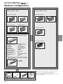
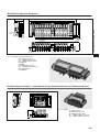
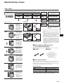
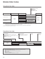
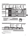
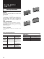
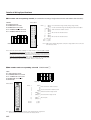
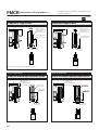
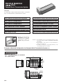
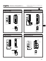
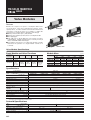
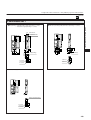
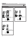
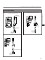
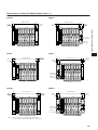
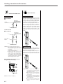
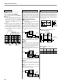
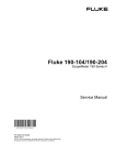
Important Precautions
Atmosphere
Avoid using it in the locations and environment
listed below, as it could result in malfunction of
the valve.
If use in such conditions is unavoidable,
always provide a cover or other adequate
protective measures:
q Location affected by strong vibration or
impact
w Location with temperature exceeding the
5∼50°C [41∼122°F] range
e Location with large change in temperature
and dew condensation
r Location exposed to direct sunlight
t Location with atmosphere containing
organic solvents, phosphate acid ester type
hydraulic oil, sulphur dioxide, chlorine gas,
or other acids
y Location directly exposed to water drops
and oil drops
u Environment where the valve body is subject
to dew condensation
i Location where the valve body is directly
exposed to metal chips, dust particulate, etc.
Media
1. Use air for the media. For the use of any
other media, consult us.
2. Air used for the cylinder should be clean air
that contains no deteriorated compressor
oil, etc. Install an air filter (filtration of 40 µm
or less) near the valve to remove collected
liquid or dust. In addition, drain the air filter
periodically.
3. Use the manifold without lubrication as
much as possible. When the actuator
requires lubrication, use Turbine Oil Class 1
(ISO VG32) or the equivalent. Avoid using
spindle oil or machine oil.
Piping
1. For the 1(P) port piping, use a size that
matches the manifold’s piping connection
port. Insufficient flow rate or pressure
could result in defective valve operation
or in insufficient actuator output.
2. When installing piping or mufflers to the
3, 5(R) port, ensure minimum exhaust
resistance.
3. On rare occasions, exhaust gas can
interfere with other valves and actuators.
In those situations, either install piping
modules at both ends for exhaust, or
install a port isolator at an intermediate
location to isolate the exhaust air, and
separate the exhaust in combination with
a piping module.
4. When a multiple number of valves are
operated simultaneously on a multistation manifold, or in high-frequency
applications, install piping modules on
both ends, and supply air from the 1(P)
port and exhaust it from the 3, 5(R) port.
(For details, see the piping module page.)
Valve module
When mounting the solenoid valves 090 series,
the solenoid is a plug-in type and valve modules
are already connected to the wiring modules by
wiring, so there is no need for wiring at each
station.
◆ Precautions for use of the twin solenoid valve
When using the base piping type twin solenoid
valve (FMWR090-4KE2), use with plugs
inserted in the 4(A) and 2(B) ports (quick
fittings) on the right side ports (see the
illustration below). Note that the twin solenoid
valve occupies 2 stations of the single
solenoid valve base, which means that valve
replacement on the base is possible.
Twin solenoid valve
Plug
(
For φ4 quick fitting:UP4
For φ6 quick fitting:UP6
For M5 female thread:PF
)
Wiring
1. Confirm positive common or negative
common.
2. Firmly insert connectors and tighten
screws.
3. Confirm the polarity of the power supply
and pin locations, and connect correctly.
(For details, see the wiring module page.)
Piping module
Piping modules are divided into 2 types, a port
type and a built-in muffler type.
In addition, the use of air supply and exhaust,
and using multiple units, make the module also
be used as a piping branch.
◆ Piping in an embedded port
When the air supply port in the built-in muffler
type has a female thread specification (FMPRFR01), use a wrench on the port’s hexagonal
portion to secure it in place while piping.
◆ Precautions
While air supply and exhaust for the valve
module are performed by using this piping
module, the number of valves in use could lead
to air supply pressure and flow rate shortages,
resulting in defective valve operation or in
insufficient actuator output. See the table below
when determining the required number of piping
modules.
Model
Number of valves
Solenoid valves 090 series
6
※Number of valves does not refer to the valves that
could be mounted on a single manifold. It is the
number of valves that enables the supply of air
simultaneously to a secondary side by using a single
piping module.
(Example) When ten 090 series solenoid valves are
mounted on a single manifold, and 8 of
those valves are in simultaneous
operation, use 2 piping modules.
(Example) When ten 090 series solenoid valves are
mounted on a single manifold, and 3 of
those valves are in simultaneous
operation, use 1 piping module.
418
FM-SOLID MANIFOLD X80M SERIES
Mounting
1. While any mounting direction is allowed,
avoid mountings that twist the manifold.
2. When connecting piping to manifolds or
other devices, flush the tubes completely by
blowing compressed air before piping.
2. If metal chips, sealing tape, or rust
generated during piping work enter, it may
cause a malfunction such as an air leakage.
3. When mounting a valve unit inside the
control panels, or when the operation
requires long energizing periods, consider
providing heat radiation.
4. The valve module cannot be operated with
the 4(A), 2(B) ports open to the atmosphere.